Templot Club Archive 2007-2020
|
|||
| author | remove search highlighting | ||
|---|---|---|---|
|
posted: 9 Aug 2015 05:18 from: Andrew Barrowman
click the date to link to this post click member name to view archived images |
Greetings fellow Templotters, As some of you already know, I've been messing about trying to print turnout bases on a 3D printer. It's fairly easy to create a 3D model of the timbers in CAD from any Templot template. It's also fairly simple to drag models of the chairs into the correct positions and orientation and combine them to produce an STL file to drive a printer. What is not so easy is producing 3D models for chairs that a) actually work, and b) don't look too horrible! I think I have reached a point where I'm limited by the printing technology itself. The results are actually a lot better than I thought they might be when I started out. Anyway, I've been making some wild guesses about chair dimensions, and I have not had a lot of luck finding anything on the Web. Any information would be greatly appreciated. (Here's a bit of track I've been using to test the latest chair design.)undefined Cheers!Andy |
||
| Attachment: attach_2150_2734_DSCN1813.JPG 2548 | |||
|
posted: 9 Aug 2015 06:11 from: Martin Wynne
click the date to link to this post click member name to view archived images |
Hi Andy, Chairs vary quite a bit across different periods and companies. There are drawings of "Standard Railway Equipment" (i.e. REA) chairs here. These would be your best bet for the majority of bullhead models: http://www.scalefour.org/downloads/gwrtracknotes/R4290A.pdf Plus several pages of specifically GWR chairs here (drawings 1734 - on): http://www.scalefour.org/resources/gwrtracknotes regards, Martin. |
||
|
posted: 9 Aug 2015 08:00 from: Andrew Barrowman
click the date to link to this post click member name to view archived images |
Hi Martin, Thank you very much! From a 3D printer perspective, the bigger the better. Based on your information it looks as if I'm not too far off. BTW, in case you had not already guessed, my ulterior motive for posting here was the possibility that someone might take this to the next level. It's beyond my capability, but I'm pretty sure someone "skilled in the art" could cook up a program that automatically combines models derived from Templot with models of the appropriate chairs to produce a stereo lithography file that can be fed to a 3D printer. Cheers!Andy |
||
|
posted: 10 Aug 2015 07:59 from: Les G click the date to link to this post click member name to view archived images |
My local Maker-Space has a number of 3d printers; I have been custodian-between-meetings for one of them for about 18months. During that time we have encountered a number of limitations of printer capability. The relevant issue with printing sleeper and chair as a component, is that the home DIY printers deposit plastic onto a plate, on ours it is heated glass. This deposition process means that any overhangs are unsupported. Test prints of arch-like components all show a degradation of the under-surface at the top of the arch, amounting to about 30 degrees of arc. It follows that the part of the chair which grips the rail will always be imprecise. Great care would be needed to obtain accurate gauging, and there would also be mechanical difficulties when fitting the rails to the chairs in a complex formation There are layer deposition processes in which the layers are formed by fusing powdered plastic which supports overhanging shapes, but the machines are very expensive. None of this takes anything away from the potential of linking Templot output to drawing software for the purpose of producing STL files for bespoke timbers for use in conventional hand-built track, then using moulded chairs eg C&L or Exactoscale. Les G |
||
|
posted: 10 Aug 2015 10:17 from: Paul Boyd
click the date to link to this post click member name to view archived images |
At work, we use a company called Shapeways for prototyping. There are various material options, some of which are eminently suitable for track work. Costs are reasonable as well - this company makes it feasible for hobbyists to upload and print using a professional SLS process. Put it this way, using Shapeways made far more sense for us than buying a "home" 3D printer with all its limitations. I suppose I should say that I have no connection with the company! |
||
|
posted: 10 Aug 2015 10:31 from: Howard
click the date to link to this post click member name to view archived images |
Les G wrote: ...the home DIY printers deposit plastic onto a plate, on ours it is heated glass. This deposition process means that any overhangs are unsupported. Test prints of arch-like components all show a degradation of the under-surface at the top of the arch, amounting to about 30 degrees of arc.For filament deposition printers (such as the Makerbot I use for the MERG kits) the effect of temperature can help overcome this. The two servo mount kits illustrated were printed at different temperatures. The higher temperature makes the filament (PLA in my case) less viscous and so it does not span the gap. 1547_100524_220000000.jpg  undefined undefinedBTW it would help if the scale/gauge were mentioned in these posts. I'm assuming O gauge, but I could be wrong. Howard Watkins. |
||
|
posted: 10 Aug 2015 10:34 from: Martin Wynne
click the date to link to this post click member name to view archived images |
Hi Paul, David Rayner uses the Shapeways service for his "Off The Rails" track parts in 7mm scale, see: http://www.shapeways.com/shops/otr topic 1503 - message 9375 regards, Martin. |
||
|
posted: 10 Aug 2015 10:54 from: Martin Wynne
click the date to link to this post click member name to view archived images |
Howard wrote:BTW it would help if the scale/gauge were mentioned in these posts. I'm assuming O gauge, but I could be wrong.Hi Howard, Andy's experiments are in 4mm scale. He has a long topic about it on RMweb: http://www.rmweb.co.uk/community/index.php?/topic/100879-printing-turnouts-on-a-3-d-printer/ By the way, your attached image is an empty file. Did you exceed the 6MB limit? It's better to use the Image Gallery for pictures: http://85a.co.uk/forum/gallery_view.php?display=ALL#gallery_top edit: I see you did upload it to the Gallery. I have edited your message to include it.  regards, Martin. |
||
|
posted: 10 Aug 2015 16:20 from: Les G click the date to link to this post click member name to view archived images |
Howard wrote: For filament deposition printers (such as the Makerbot I use for the MERG kits) the effect of temperature can help overcome this. The two servo mount kits illustrated were printed at different temperatures. The higher temperature makes the filament (PLA in my case) less viscous and so it does not span the gap. Howard, What you describe matches our droopy experience of overhangs with a RepRap, and with a Mendel90. It is not too serious a problem generally, one can make an allowance in the model to allow a sufficient degree of manual fettling; or design the component to avoid it. Model railway Scale is not relevant to the work we have been doing, but when I model it is usually in 4mm. As a matter of interest, what temperature do you use for your extrusion of PLA ? Les G |
||
|
posted: 10 Aug 2015 19:13 from: Trevor Walling
click the date to link to this post click member name to view archived images |
Les G wrote: Hello, For some reason I always thought higher temperatures meant greater viscosity and more likelihood of unsupported overhangs drooping. Regards. Trevor. |
||
|
posted: 11 Aug 2015 11:10 from: Les G click the date to link to this post click member name to view archived images |
You are correct: Lower viscosity = stiffer; higher viscosity = more free flowing. Higher temperature makes the plastic more liquid, and more likely to droop. This is why temperature and filament feed speed are controlled. Hence my query about extruder temperature for successful bridging. Les G |
||
| Last edited on 11 Aug 2015 11:18 by Les G |
|||
|
posted: 12 Aug 2015 01:32 from: Andrew Barrowman
click the date to link to this post click member name to view archived images |
Ah yes! This sample is OO gauge - I should have mentioned that. Thanks Martin. I'm using the cheapest printer I could find a couple of years ago, a Printrbot Simple. The unsupported overhang issue does not present a problem for me, and I'm able to get very consistent dimension and gauge results. At the moment I'm working on optimizing the chair designs for turnouts and finding the method that allows me to generate a turnout with the least effort. I'll post the results when I have something I'm satisfied with. BTW, I'm printing with PLA through a 0.25 mm nozzle. PLA is interesting stuff. Although it has a rather low melting point, it's quite hard, and it makes turnout bases that are surprisingly rigid, sufficiently so that it's possible to drag straight rail through the chairs for wings and checkrails. More to follow (PS - My Templot message alerts are no longer going to spam.) |
||
| Last edited on 12 Aug 2015 01:43 by Andrew Barrowman |
|||
|
posted: 12 Aug 2015 10:26 from: LSWRArt
click the date to link to this post click member name to view archived images |
There are some nice 3D printed 7mm chairs here - unfortunately not available in 4mm. http://www.shapeways.com/shops/otr I have used some of these check rail chairs for point construction. The only problem is that, for super fine detail, the plastic is quite hard and therefore rather brittle. You have to be quite careful pushing the chairs onto the rail - especially as you are trying to move along two rails as once, but they are certainly nicely detailed and look the part. Certainly at this scale and with these hard plastics there is no problem with droop. Regards, Arthur |
||
|
posted: 12 Aug 2015 12:40 from: Howard
click the date to link to this post click member name to view archived images |
Les G wrote: You are correct: Lower viscosity = stiffer; higher viscosity = more free flowing.The left hand image was done at 200 degrees, the right hand one (with drooping filament) at 220 degrees. Too low a temperature can mean parts do not adhere to the bed plate. Howard. |
||
|
posted: 12 Aug 2015 12:44 from: Howard
click the date to link to this post click member name to view archived images |
Martin Wynne wrote:I see you did upload it to the Gallery. I have edited your message to include it.Thanks Martin, I don't know why the picture was not included even though it was in the Gallery. I must be doing something wrong. Howard. |
||
|
posted: 12 Aug 2015 21:58 from: Les G click the date to link to this post click member name to view archived images |
Howard wrote: The left hand image was done at 200 degrees, the right hand one (with drooping filament) at 220 degrees. Too low a temperature can mean parts do not adhere to the bed plate. Thank you Howard, We are currently printing PLA at 210 initial then 200 for the main print. Our Mendel90 has a nozzle at 0.4 mm. We are using a glass plate heated to 60 degrees. Adhesion is rarely a problem as long as the glass is squeaky clean; we use paper towel and meths for cleaning between prints. There have been adhesion problems with small diameter prints at around 6 mill diameter or less; a cure for this was to place the small cylinder on a sacrificial larger thin disc base and truncated cone. Another problem was found when printing a cylinder with 2mm dia spigot; the plastic became distorted due to insufficient cooling time between layers. This was completely resolved by printing six components at a time. It took about seven seconds to complete each layer in the set, by which time the previous layer had cooled sufficiently to be stable. regards Les G |
||
| Last edited on 12 Aug 2015 21:59 by Les G |
|||
|
posted: 13 Aug 2015 09:51 from: Howard
click the date to link to this post click member name to view archived images |
Les G wrote: The printer used by MERG is a Makerbot Replicator2. This also has a 0.4mm nozzle but no heated bed plate. For a large box (17cm x 8cm) I had problems with a corner lifting during printing. I tried helper discs http://www.makerbot.com/blog/2013/04/19/keep-corners-flat-with-makerwares-helper-discs but this did not solve the problem. I am now printing on BuildTak and that works http://shop.3dfilaprint.com/buildtak-3d-printing-platform-surface-1200-p.asp For very small objects I have also used double sided adhesive tape on top of the normal blue painter's tape. Howard. |
||
|
posted: 13 Aug 2015 14:00 from: Les G click the date to link to this post click member name to view archived images |
I have read about the problems of adhesion on unheated plates. There appears to be a high level of frustration from those who describe the need for cleaning off adhesive prior to fitting new tape. Contrast that with a 30 second wipe and polish with a bit of paper towel and a dab of methylated spirit. In my view, the heated plate solution is the logical way to go. It also provides a very smooth base surface which can be used to advantage. Les G |
||
| Last edited on 13 Aug 2015 14:01 by Les G |
|||
|
posted: 13 Aug 2015 17:28 from: Andrew Barrowman
click the date to link to this post click member name to view archived images |
I'm using blue masking tape on an unheated metal bed. Seems to work well enough for me. I always give the tape a light rub with sandpaper between prints to remove any residue from the PLA and to provide a bit of key on the surface. The Z-axis zero position is critical. My printer is a bit flimsy, so I have to keep a close eye on the Z adjustment to ensure a good first layer. I've also found it's better to use a honeycomb fill on the bottom layer rather than make it solid. |
||
|
posted: 2 Jan 2016 03:52 from: Andrew Barrowman
click the date to link to this post click member name to view archived images |
Turnout stereo lithography file. | ||
| Attachment: attach_2194_2734_Doh6p5v5R.stl 384 | |||
|
posted: 2 Jan 2016 03:56 from: Martin Wynne
click the date to link to this post click member name to view archived images |
Andrew Barrowman wrote: Turnout stereo lithography file.Hi Andy, Thanks for the file. I have downloaded it. Now what?  Do you have a link for the software to use it? regards, Martin. |
||
|
posted: 2 Jan 2016 10:27 from: Howard
click the date to link to this post click member name to view archived images |
Martin Wynne wrote: Andrew Barrowman wrote:You can use the free download of the Makerbot Desktop to view the fileTurnout stereo lithography file.Hi Andy, http://www.makerbot.com/desktop I had to rescale the turnout to fit, undefined At 0.1mm resolution it would take 1.5 hours to print; I might give it a go later. 1547_020513_550000000.png  Howard Watkins |
||
|
posted: 2 Jan 2016 18:23 from: Andrew Barrowman
click the date to link to this post click member name to view archived images |
Howard wrote: Martin Wynne wrote:Mind how you go with that Howard. It may not be what you expect. We parked it there so that Martin could take a look at it with Meshlab.Andrew Barrowman wrote:You can use the free download of the Makerbot Desktop to view the filehttp://www.makerbot.com/desktopTurnout stereo lithography file.Hi Andy, Before you try to print it, you might want to run it through Netfabb to repair any defects. The .stl was produced in TurboCADpro16, and it sometimes has issues. Also, you might want to add webs to connect the timbers. I left them out for viewing clarity. I have attached the .box file that generated the design. You can find photos of similar turnouts I produced on RMweb. My "handle" there is AndyID. I'll post some of the shots on this thread in a bit. |
||
| Attachment: attach_2195_2734_Doh6p5v1.box 359 | |||
|
posted: 2 Jan 2016 19:04 from: Martin Wynne
click the date to link to this post click member name to view archived images |
Hi Andy, MeshLab keeps crashing on my system. For simply viewing and rotating the image, the free eDrawings viewer from Solidworks seems to be working much better. Download from: http://www.edrawingsviewer.com 2_021402_240000000.png  regards, Martin. |
||
|
posted: 2 Jan 2016 20:07 from: Andrew Barrowman
click the date to link to this post click member name to view archived images |
Howard wrote: Martin Wynne wrote:Andrew Barrowman wrote:You can use the free download of the Makerbot Desktop to view the fileTurnout stereo lithography file.Hi Andy, Hi Howard, I just realized that you might be going to print the rails too. They are only there for cosmetic effect. They are not designed for printing. The rail web is very thin, and you would probably need to add supports of some sort to prevent sagging. I have printed check rails in the past, but not using that design. regards,Andy |
||
|
posted: 2 Jan 2016 21:04 from: Martin Wynne
click the date to link to this post click member name to view archived images |
Hi Andy, RMweb has gone down, so here is the .box file I just posted on there. This is for the 4ft-1.5in gauge templates which I have been playing with. I'm not sure what you are waiting for? regards, Martin. |
||
| Attachment: attach_2196_2734_4ft_1p5in_gauge_templates_00_bf.box 309 | |||
|
posted: 2 Jan 2016 21:10 from: Andrew Barrowman
click the date to link to this post click member name to view archived images |
Yes, I think I broke it when I replied Thanks Martin. That's exactly what I need. I'll add the 3D elements to it so we can view it. |
||
|
posted: 3 Jan 2016 04:29 from: Andrew Barrowman
click the date to link to this post click member name to view archived images |
undefined I uploaded them to the Gallery but I can't seem to figure out how to Insert them into the message. (Using Chrome on Windows10.) edit: Now resolved Using FireFox 2983_022322_090000004.jpg  2983_022322_080000000.jpg  2983_022322_080000001.jpg  2983_022322_080000002.jpg  2983_022322_090000003.jpg  |
||
| Last edited on 4 Jan 2016 07:35 by Andrew Barrowman |
|||
|
posted: 3 Jan 2016 07:24 from: Andrew Barrowman
click the date to link to this post click member name to view archived images |
.stl file of a 00-BF V-6 turnout attached. This file is intended for viewing only. It requires further editing before 3D printing. |
||
| Attachment: attach_2198_2734_MW1b.stl 289 | |||
|
posted: 3 Jan 2016 10:17 from: Martin Wynne
click the date to link to this post click member name to view archived images |
Andrew Barrowman wrote: I uploaded them to the Gallery but I can't seem to figure out how to Insert them into the message.Hi Andy, Google Chrome is the new Internet Explorer, doing its own thing with web sites.  Generally Firefox is the best option for this site (and many others). This is how to insert images using Google Chrome (and Safari): 1. don't use the long Gallery buttons on the posting editor. Instead use the blue Gallery Upload button at the very top of the page. It will open in a new tab, so that you don't lose your post. 2. upload your image(s) to the Gallery. 3. display the required image in the Gallery. 4. right-click on it, and select Copy Image Location or Copy Image Address to get the image URL. 5. back on the posting page, click this button: image.gif  6. paste in the copied URL and click OK. 7. the image will be inserted in your post. It may be immediately visible, or you may need to click Preview to see it (depending on how your browser is feeling today). After previewing you can scroll back down to continue posting. This web site uses some rather old code. It's been rock-solid reliable for years, but unfortunately browsers keep changing and it needs updating to something more modern. When I can find the time. regards, Martin. |
||
|
posted: 3 Jan 2016 11:46 from: Martin Wynne
click the date to link to this post click member name to view archived images |
Andrew Barrowman wrote: .stl file of a 00-BF V-6 turnout attached.Hi Andy, Looking very good. Thanks for doing this. 2_030641_500000000.png  Note that the crossing chairs (A, B, C, X, Y) need to be skewed so that they are square to the centre-line of the vee. Also chair "A" should be a slab & bracket design, with a through bolt (for a 1950s design). We will let you off that (for now).  The old style of cast "A" chair is ok for earlier periods. regards, Martin. |
||
|
posted: 3 Jan 2016 12:17 from: Martin Wynne
click the date to link to this post click member name to view archived images |
Hi Andy, I have increased the upload limit to 10MB in case you need to upload larger STL files. Attachments on this forum are stored as a BLOB in the database (Binary Large Object) which is not ideal but it seems to be working fine in practice. Fortunately the donations fund is happily covering the web costs at present. regards, Martin. |
||
|
posted: 3 Jan 2016 13:03 from: Martin Wynne
click the date to link to this post click member name to view archived images |
Hi Andy, This is Templot's native DXF export (3D setting), viewed in eDrawings: (This is the 1:7.5 crossing.) 2_030750_010000000.png  It doesn't seem to be possible to import a DXF into MeshLab? It's now about 15 years since I wrote the DXF export function in Templot, and things have obviously moved on. How would I go about implementing an export for 3-D printing files? There seems to be a bewildering array of file formats to choose from, and a lack of good documentation about their internal structure (unless I'm missing the obvious -- I found this: http://mech.fsv.cvut.cz/~dr/papers/Lisbon04/node2.html ). regards, Martin. |
||
|
posted: 3 Jan 2016 18:29 from: Andrew Barrowman
click the date to link to this post click member name to view archived images |
Thanks for all the help Martin. I shall attend to those errant chairs shortly Actually, if you look closely you mght detect that they use a sort of slab and bracket construction. The base with the bolt heads is a different model (Block in CAD) from the thing that holds the rail. All I need to do is realign the base "slab". I'll post a couple of screen shots from TurboCAD later to shed some light on the assembly process. I'm lazy, so I had to make it as easy as possible. From what I can see the STL file format seems to be emerging as the common interchange standard for 3-D printing, but it's all quite new to me so I could be entirely wrong. Cheers, Andy |
||
|
posted: 4 Jan 2016 03:42 from: Andrew Barrowman
click the date to link to this post click member name to view archived images |
Andrew Barrowman wrote: .stl file of a 00-BF V-6 turnout attached.New and improved! |
||
| Attachment: attach_2199_2734_MW1e.stl 308 | |||
|
posted: 4 Jan 2016 03:44 from: Andrew Barrowman
click the date to link to this post click member name to view archived images |
Andrew Barrowman wrote: Andrew Barrowman wrote:I took the liberty of equalizing the timbers on this version..stl file of a 00-BF V-6 turnout attached.New and improved! |
||
| Attachment: attach_2200_2734_MW1g.stl 308 | |||
|
posted: 4 Jan 2016 06:47 from: Andrew Barrowman
click the date to link to this post click member name to view archived images |
Some screenshots of the assembly process using TurboCAD. The outline template is imported into TurboCAD as a DXF file from Templot. Only the gauge edge of the rail is used. It's best not to include the other edge in the DXF. The timber outlines and centerlines are used. The Blocks panel to the right of the first shot contains models for the various chairs required. They all have a reference point that lies on the plane corresponding with the bottom surface of the timbers. The template is placed on that plane. The various blocks are simply dragged from the Blocks panel and their reference (yellow dot) is snapped on to the template at the intersection of the rail gauge edge and the timber centerline. TurboCAD has a rubber stamp feature that lets you stamp the same block repeatedly with one mouse click. I've used it here to replicate a number of three bolt chairs on the template. 2983_040211_290000000.png  Some of the chairs will need to be rotated after stamping them in place. 2983_040211_300000001.png  Here one chair has been selected and has been rotated and realigned with the direction of the rail by dragging the X handle and snapping it on to the rail edge. 2983_040211_310000002.png  The timbers are extruded to the desired height with two mouse clicks. I have extruded one in this shot but I find it best to position all the chairs before extruding the timbers. 2983_040211_310000003.png  To avoid having to make lots of different chairs for all the possible crossing angles I make the chairs at the Vee from a few sub-components. Slightly more complicated, but not much. Other than adding webs to interconnect the timbers, that's about all there is too it. I do not "add" the chairs to the timbers to make a single solid object. There is no need to do that, and if I did, it would make it much more difficult to revise a turnout design. Using blocks allows me to modify a block design and immediately apply it to every instance of that block in the turnout. |
||
| Last edited on 4 Jan 2016 07:30 by Andrew Barrowman |
|||
|
posted: 4 Jan 2016 13:12 from: Martin Wynne
click the date to link to this post click member name to view archived images |
Hi Andy, Many thanks for that. It seems that adding and aligning the chairs is a tedious process? One which Templot might possibly be able to do itself? Then you could create one-off 3D files to print any template in a full track plan, rather than a few fixed turnout sizes. It would likely need a "shove chairs" function similar to shoving timbers to resolve any conflicts, such as replacing an ordinary chair with a bridge chair where needed. Which means the chairs would also need to be visible on the trackpad. So the first question is -- are your chairs in a format which will import into Templot using the existing DXF import function (in the background shapes)? Is it possible you could send me, or attach here, a DXF file containing just one of your chairs? I can then experiment with getting Templot to include it in the DXF export. Preferably the file would be in the DXF text format, rather than binary, so that I can read it. I can probably convert it if not. What I'm still very hazy about is how we get from a drawing in TurboCAD to something a 3D printer can use? I've been reading that the STL format is many years old, dating from before 3D printers became generally available, and is generally regarded as too low in resolution for them? Does your printer lay the filaments in horizontal sections, i.e. everything at one Z dimension in one go, and then step up to the next section and repeat? Or does the head move in 3 dimensions simultaneously, laying down flat angled faces for example? I spent years programming for that sort of thing in CNC milling using ball cutters and special-profiled D-cutters, but I'm thinking 3D printing is not quite the same. For example is a round filament the only option? I can see that in some applications a nozzle which extruded a flat strip might be more useful, especially if could by done at an angle from a swivellable nozzle, adding a K dimension to the X,Y,Z. I can see that I am going to have to get one of these 3D printers and experiment before I can make sensible changes in Templot. I have found this before, no amount of asking folks or reading docs gets me enough information. For example making Templot dpi-aware for hi-res tablet computers. The only way I could do that was to get one and try it. It was a lot of work, and expensive, but I'm very pleased with the result. But there has been minimal feedback on the subject. I wonder how many Templot users do have 3D printers or intend getting one? regards, Martin. |
||
|
posted: 4 Jan 2016 19:18 from: Trevor Walling
click the date to link to this post click member name to view archived images |
Hello, This stuff is really interesting and impressive. Using Templot for 3D printing would take it to a whole new level. I I wonder how many Templot users do have 3D printers or intend getting one?I have a printer from "RepRapPro". A Mendel from about two or three years ago.It has been superseded by more capable and easier to build models.Information about most aspects is available on their web site. The speed of change and progress in this field is breathtaking. There are sites where you can download files of objects to print "Thingiverse" being one. I haven't got round to learning a CAD program to design something for printing myself yet, but it is on my ToDo list. Regards. |
||
|
posted: 4 Jan 2016 20:06 from: Martin Wynne
click the date to link to this post click member name to view archived images |
Martin Wynne wrote:This is for the 4ft-1.5in gauge templates which I have been playing with.Here are the same templates converted to 4ft-0.5/8in gauge in 4-SF (16.2mm gauge). There is no suggestion that 4-SF is suitable for commercial RTR pointwork, so I have changed the length of these to match the vee-rail joints in the usual way (CTRL-6 and CTRL-8 peg positions). The plain track is set to 27 8ft sleepers per 60ft rail, with similar spacings in the turnouts. The idea is to create prototype 4ft-0.5/8in track to carry the same weight of traffic as 4ft-8.1/2in gauge track. Martin. |
||
| Attachment: attach_2201_2734_4ft_0p6in_gauge_templates_4_sf.box 334 | |||
|
posted: 4 Jan 2016 20:33 from: Nigel Brown click the date to link to this post click member name to view archived images |
Martin Wynne wrote: I wonder how many Templot users do have 3D printers or intend getting one?Hi Martin I'm interested in 3D printing, mainly because it looks to be a means of creating bits and pieces in 3mm/ft which aren't there at the moment. The idea of taking say a drawing of a dome or chimney and being able to convert it into something printable is enormously attractive, particularly for the more uncommon prototypes I'm thinking of. However, I'd almost certainly use Shapeways (or other similar services), partly because I think they can afford a much higher quality printer than I could, and it would save me a lot of time, and probably money, going in that directive. Today's home printer could be junk tomorrow. I'll stick to working out the software Cheers Nigel |
||
|
posted: 5 Jan 2016 00:23 from: Andrew Barrowman
click the date to link to this post click member name to view archived images |
Martin Wynne wrote: Hi Andy,Hi Martin, Three bolt attached. It's the only format that TurboCAD allows me to save it in. Probably binary, but I don't really know. The reference point should lie at the intersection of the two lines floating beneath the solid body. That should put the bottom surface of the rail 1.8 mm above the bottom surface of the 1.2 mm thick timbers on my prints. BTW, this chair works with SMP Code 75 BH rail, but it might need to be adjusted for BH rail from other suppliers. It's not too terribly tedious to position the chairs on the template, but it would be interesting to see if it could be automated. It might depend on whether or not you want to completely eliminate the CAD step. If a CAD step was retained, one way to accelerate the process would be to put dummy "blocks" in the 3D DXF from Templot. There would be different dummies for the various chair types. They would only need to be positioned and oriented correctly. TurboCAD lets you select a block in a model then replace it and all the other blocks of the same name with a different block. With that method it would not take long to populate a template with the desired set of chairs and it would be independent of gauge, scale, clearances etc. If the CAD step was to be eliminated, I think Templot would need to include a similar feature that allowed the user to include a library of chairs that Templot selected from and positioned in the 3D model. I don't think a "universal" set of chairs will work too well. For example, if you were building 7mm turnouts (which I think is a really great application for 3D printing) you would probably want to include a lot more refinement than it is possible to include at 4mm scale; to some extent the chairs have to be designed to reflect the limitations of the printing process and print medium at the desired scale. There are a few more steps involved to print a CAD model. I'll list them the way I happen to do it: 1. Create the 3D model in native TurboCAD format. 2. Save the TurboCAD model as a STL file. (It's really a bunch of models in their desired relative overlapping positions.) 3. Import the STL file into Netfabb Basic - it repairs any holes and other issues and creates a single surface model in another STL file. 4. Import the repaired STL file from Netfabb into a slicer program, in my case SLIC3R. This takes the STL file of the model and slices into layers which are exported as a G-code file to drive the 3D printer. Yes, the printer prints a single horizontal layer (slice) at one Z axis height before moving on to the next layer. The layers are usually all the same thickness, but they do not have to be. It is possible to generate custom G-code that does it differently, but I suspect that would be a major undertaking. The big issue with additive printing is ensuring that a layer fuses properly with the previous layer. That's difficult enough in a single plane. Doing it in 3D motion is probably not impossible, but I suspect it would take a lot of experimentation to get satisfactory results. I probably only answered half your questions, so keep asking! Best, Andy |
||
| Attachment: attach_2202_2734_Chair1.dxf 431 | |||
|
posted: 5 Jan 2016 07:34 from: Martin Wynne
click the date to link to this post click member name to view archived images |
Andrew Barrowman wrote:I probably only answered half your questions, so keep asking!Hi Andy, Thanks for the file. It is indeed in the text version of DXF so I can read it, thanks for that. (If you change the file extension to .txt you can read it in Windows Notepad or wherever.) Unfortunately I haven't been able to extract anything meaningful from it. I tried opening it in half a dozen programs, and the only one which would even look at it was, er, Templot. I used the DXF import in the background shapes (you saved it in INCH units), and got this: 2_050214_470000000.png  but no sign of a chair. It also included a cross-hairs target mark at (67000, 21486) mm which as you can imagine caused some indigestion. But even after removing that, the file still won't display anything in any other software. Which is puzzling because they ought to display at least the above, if Templot can. It does include a chunk of unreadable code at one place in the file, which means nothing to me. I know I am a long way from being up to date in CAD software, but even the latest eDrawings2016 displays only a few single dots. Is there any way you can save it in a format I can use? For example after selecting DXF file type in the TurboCAD save dialog, can you click the Setup button and make these settings: 2_050214_480000001.png  Reading your description of the post-processing which these files need before they become usable on the 3D printer, it seems this whole process is still a long way from being very user friendly? regards, Martin. |
||
|
posted: 5 Jan 2016 08:15 from: Andrew Barrowman
click the date to link to this post click member name to view archived images |
Attached version might be better. I removed the junk that was in a 2-D page tab and set the origin to something more sensible. This is what I see when I use setup (I didn't even know it was there!) Does any of it look helpful? It does not mean much to me. 2983_050309_580000000.png  Yes, the process isn't exactly "shake and bake", but the additional steps are quite mechanical and require little concentration. ab |
||
|
posted: 5 Jan 2016 08:32 from: Andrew Barrowman
click the date to link to this post click member name to view archived images |
Ah! I can see it using eDrawings viewer. It's in the bottom right-hand corner. There are some dots in the file that need to be eliminated. | ||
|
posted: 5 Jan 2016 11:06 from: Charles Orr
click the date to link to this post click member name to view archived images |
Hi Martin, I have a Rep Rap Pro Omerod which I built from a kit. It took some time to set up but generally produces acceptable prints. I am going to get a Maker Bot Replicator 2 very soon. This the one that MERG uses to produce some of its kits. Best regards Charles |
||
|
posted: 5 Jan 2016 11:20 from: johnbirch72
click the date to link to this post click member name to view archived images |
Nigel I would certainly stick with outside printers for 3D work now. I use Chris Ward (http://www.cwrailways.com) who produces good results and tends to be cheaper than Shapeways with faster turnround which removes a lot of frustration. John |
||
|
posted: 5 Jan 2016 12:28 from: Martin Wynne
click the date to link to this post click member name to view archived images |
Andrew Barrowman wrote: Attached version might be better. I removed the junk that was in a 2-D page tab and set the origin to something more sensible.Hi Andy, Attached version? Did you forget to attach it? In the setup, please can you try ticking these options: 2_050642_530000000.png  It may announce that what you have can't be saved in that format, but it's worth a try. I'm intending to get a more up-to-date CAD package so that I can make sense of all the 3D printer stuff which is now available. I do have DesignSparkMechanical, which is free software from RS Components (a big electronics distributor in the UK) intended for rapid prototyping for 3D printing. It can open and create STL files -- this is your STL file: 2_050703_120000000.png  http://www.rs-online.com/designspark/electronics/eng/page/mechanical Be warned, the download is a massive file -- 467 MB. It declares itself "unlicensed" to open DXF files, but it is willing to save to DXF. So I can possibly extract the chairs from the above and get them into DXF. Thanks again, I will do a bit more experimenting. regards, Martin. |
||
|
posted: 5 Jan 2016 16:34 from: Andrew Barrowman
click the date to link to this post click member name to view archived images |
Well I thought I had attached it Trying again..... |
||
| Attachment: attach_2204_2734_Chair2.dxf 388 | |||
|
posted: 5 Jan 2016 17:11 from: Martin Wynne
click the date to link to this post click member name to view archived images |
Andrew Barrowman wrote: Well I thought I had attached itHi Andy, That's great, many thanks: 2_051203_480000000.png  Hopefully I can get Templot to insert it in the DXF output where required. It contains this chunk of code which means nothing to me, but hopefully if inserted "as-is" it will work. Any idea where I should be looking to discover how to decode this? 2_051206_300000000.png  Now to conduct some experiments -- I may be some time... edit: well this is a start: http://help.autodesk.com/view/ACD/2016/ENU/?guid=GUID-19AB1C40-0BE0-4F32-BCAB-04B37044A0D3 regards, Martin. |
||
|
posted: 5 Jan 2016 17:19 from: Andrew Barrowman
click the date to link to this post click member name to view archived images |
Hi Martin, First screen grab is chair2.dxf viewed in eDrawings. The chair is in the bottom right hand corner. I think the five dots in the upper left hand corner could be elements of a 3-D axes indicator. I can reload the dxf file into Turbocad without a problem. The dots are not graphic elements in the file. The second grab is the zoomed in view of the chair. I tried saving a version with the settings you suggested, but the chair is not visible when I view it in eDrawings. I've attached that version (chair3.dxf) to this message. ab 2983_051205_200000000.png  2983_051205_580000000.jpg 2983_051205_580000000.jpg |
||
| Attachment: attach_2205_2734_Chair3.dxf 359 | |||
|
posted: 5 Jan 2016 17:22 from: Andrew Barrowman
click the date to link to this post click member name to view archived images |
Snap! No clue at all about the junk I'm afraid. I've never even looked in any of the files. |
||
|
posted: 5 Jan 2016 17:28 from: Martin Wynne
click the date to link to this post click member name to view archived images |
Andrew Barrowman wrote: No clue at all about the junk I'm afraid. I've never even looked in any of the files.I don't think it is junk, I think it is your 3D data. Many thanks for the second file. Now I can diff the two and discover how to set the DXF version number in the exported file, to match the above "junk". At first sight the two files are very similar. Thanks again, Martin. |
||
|
posted: 6 Jan 2016 00:14 from: Martin Wynne
click the date to link to this post click member name to view archived images |
Hi Andy, First signs that this might work. A couple of your chairs in Templot's background shapes:2_051906_110000000.png  Templot wouldn't import your DXF file. But it would after I opened it in my old copy of TurboCAD and saved it again. The first task would seem to be to get some radiused corners on these 2D chairs. There is already a dialog for some chair data -- it has been in Templot for about 15 years and never yet used, see real > chairs / baseplates > chair / baseplate data... Click the ? info buttons for some notes about each dimension. regards, Martin. |
||
|
posted: 6 Jan 2016 01:20 from: Andrew Barrowman
click the date to link to this post click member name to view archived images |
Hi Martin, For the sake of drawn appearance you might radius the corners, but for printing at this scale it's a waste of time, it's only going to make the stl file even bigger, and that slows down the pre-printing process, a lot. (I know this first-hand.) The printer automatically puts a radius on the corners. I'm interested to see if you can insert a "blocks" into the template. I'll send you a file that includes a few examples in a bit. Best, ab |
||
|
posted: 6 Jan 2016 20:41 from: Martin Wynne
click the date to link to this post click member name to view archived images |
Andrew Barrowman wrote:For the sake of drawn appearance you might radius the corners, but for printing at this scale it's a waste of time, it's only going to make the stl file even bigger, and that slows down the pre-printing process, a lot. (I know this first-hand.)Hi Andy, I was thinking that the presence of the sharp corners in 2D might be a factor when shoving chairs to avoid conflicts, for example: 2_061531_270000000.png  (That is from Len Newman's P4 templates, which are available as downloads to Scalefour Society members. I'm currently working to get these usable in the background shapes as metafiles.) I'm thinking that we are going to need 2 linked chair objects. One in 2D to see and shove on the trackpad and use in 2D DXF exports, and one suitable for 3D printing to include in 3D exports (DXF or STL). regards, Martin. |
||
|
posted: 6 Jan 2016 22:20 from: Andrew Barrowman
click the date to link to this post click member name to view archived images |
Hi Martin, I see what you mean. I actually allow the 3-D chair models to overlap slightly if they are too close But it would be nice to see the most realistic chairs on the templates. Printing for 7mm scale (or greater) could take advantage of a lot more detail."I'm thinking that we are going to need 2 linked chair objects. One in 2D to see and shove on the trackpad and use in 2D DXF exports, and one suitable for 3D printing to include in 3D exports (DXF or STL)." Yes, I think you are correct. I'm a bit concerned that, if Templot produces an STL file for the printer, Templot is now to a great extent responsible for the results. I would suggest you don't provide that option until you have tried a bit of printing yourself. Initially I'd suggest DXF output only. That's why I'm interested to see if Templot can output chairs as correctly positioned and oriented blocks. That allows a user to easily substitute their own chairs in CAD. The Templot "chair" could be a simple box shape. The blocks might only need to be two dimensional representations in the template. I'm trying to see if that's possible, but so far I don't have conclusive results. Best, ab |
||
|
posted: 6 Jan 2016 22:29 from: Andrew Barrowman
click the date to link to this post click member name to view archived images |
I should have said "see if I can export and import blocks in DXF format" I'm trying to get TurboCAD to do it, but no luck so far. | ||
|
posted: 6 Jan 2016 23:18 from: Martin Wynne
click the date to link to this post click member name to view archived images |
Hi Andy, I feel that I'm sinking in a sea of file formats. This is your DXF file. At present Templot can't import anything from this: 2_061809_060000000.png  This is the result of opening it in TurboCAD and saving it in R12 version of DXF: 2_061811_080000000.png  Templot happily imports this using my original 15-year-old code. Also, the file doesn't contain anything which I can't read. From TurboCAD I can export this in 3DS format, which looks identical, and there are some online tools for converting 3DS to STL. However, when I tried them the results look nothing like a chair. I'm not planning to create STL files in Templot. But what I would like to find is a simple path from the DXF files which Templot can export, to STL files (or some other format related to 3D printing). As I recall you are doing that via TurboCAD? However my old copy of TurboCAD won't save in STL format. regards, Martin. |
||
|
posted: 7 Jan 2016 03:17 from: Andrew Barrowman
click the date to link to this post click member name to view archived images |
Hi Martin, Here is a very basic DXF file. It seems to be compatible with TurbocadPro16 and TurbocadDeluxe21 both for reading and writing. The file consists of two "blocks", a 2D rectangle block and a 2D triangle block. If it's possible to insert some copies of these into a DXF template at various locations and with various alignments, and they survive as identifiable blocks when I import the DXF into Turbocad, I should be able to immediately substitute 3D chair blocks at the same locations and with the same alignments. If that does not work, we might be up a gum tree Cheers, ab |
||
| Attachment: attach_2206_2734_DXFtest1.dxf 319 | |||
|
posted: 7 Jan 2016 08:49 from: Martin Wynne
click the date to link to this post click member name to view archived images |
Andrew Barrowman wrote: Here is a very basic DXF file. It seems to be compatible with TurbocadPro16 and TurbocadDeluxe21 both for reading and writing. The file consists of two "blocks", a 2D rectangle block and a 2D triangle block.Hi Andy, I'm not clear what you want me to do with this file? It won't display in my old copy of TurboCAD, nor import into Templot. However, I managed to get it into Templot by: 1. opening it in ProgeCAD Smart 2. saving in DXF R14 format 3. opening that in TurboCAD 4. saving in DXF R12 format with exploded blocks 5. importing into Templot: 2_070347_090000000.png  What now? This is what I'm seeing in Edrawings, and also in ProgeCAD Smart: 2_070315_310000000.png  2_070316_310000000.png  2_070327_300000000.png  regards, Martin. |
||
|
posted: 7 Jan 2016 09:18 from: Martin Wynne
click the date to link to this post click member name to view archived images |
p.s. I can also get it into Templot by exporting from ProgeCAD as an EMF metafile, and importing that into Templot as a picture shape: 2_070414_100000000.png  From which I can probably extract the metafile records, which could then be included in the DXF export. (This is what I'm currently experimenting with for the P4 templates which I mentioned earlier.) Martin. |
||
|
posted: 7 Jan 2016 17:38 from: Andrew Barrowman
click the date to link to this post click member name to view archived images |
Hi Martin, Sorry it's getting so complicated. I found some info on blocks here http://www.autodesk.com/techpubs/autocad/acadr14/dxf/blocks_in_dxf_files_al_u05_c.htm I can see these block structures in the last file I posted, so that is at least something. What I hope we might be able to do is get Templot to produce a DXF file that has simple two-dimensional "blocks" positioned on the template at the places where chairs should be located. Each type of chair (3 bolt, bridge, check, etc, etc) would be represented by a unique two-dimensional block in the DXF exported by Templot. (If I understand correctly, they don't even need to be different shapes. Each type just needs to have a unique block name.) The rectangle and triangle blocks I included in the test file are just examples of two-dimensional blocks that we might use for testing purposes. There is no reason to use them if you can produce blocks in the template by another method. If you can create a DXF in Templot with the 2-D blocks at the correct locations on the timbers it is very simple to substitute the actual 3-D chairs in TurboCAD for the 2-D blocks in the DXF imported from Templot. In Turbocad I can replace all the blocks with a particular name with blocks of another name with a couple of keystrokes. Hope this makes a bit more sense Andy |
||
|
posted: 7 Jan 2016 18:13 from: Martin Wynne
click the date to link to this post click member name to view archived images |
Andrew Barrowman wrote: What I hope we might be able to do is get Templot to produce a DXF file that has simple two-dimensional "blocks" positioned on the template at the places where chairs should be located. Each type of chair (3 bolt, bridge, check, etc, etc) would be represented by a unique two-dimensional block in the DXF exported by Templot.Hi Andy, That's exactly what I have been working on today. I have concluded that these "block markers" can't be easily included in the background shapes or loaded via the DXF import. They need to be something separate, generated by Templot itself, and included in the DXF export. This requires a new layer in the DXF export, so will need some work on the DXF export code (which I haven't looked at for years). I have dusted off (literally) my 1985 AutoCAD User Handbook and been re-reading the chapter on generating DXF files. The block information is substantially the same as in your link, but thanks for that.If I don't need to include in the export any previously-imported complex 3D data, the whole process moves up several notches on the doable scale. So I hope to have something you can try fairly soon. regards, Martin. |
||
|
posted: 7 Jan 2016 18:55 from: Andrew Barrowman
click the date to link to this post click member name to view archived images |
Great! Thanks. | ||
|
posted: 7 Jan 2016 20:43 from: Andrew Barrowman
click the date to link to this post click member name to view archived images |
Hi Martin As I mentioned, I have TC16Pro and TCdeluxe21. They don't have compatible native file formats, but they can exchange files in DXF format. I have attached the DFX for the latest version of the RMweb rendering without the rails but including webs to attach the timbers. I think I still need to adjust a couple of chairs for 1.3 mm check rail clearance, but it should be OK otherwise. TCdeluxe21 is available in the US for $70 from CAD and Graphics at the moment (there is also later version available for a bit more). This file should be editable in TCdeluxe21, and it TCdeluxe21 can output STL files. There seem to be a large number of duplicated blocks with auto-generated name associated with this file, but the ones I produced seem to be there too. There is also an free evaluation version of TCdeluxe available, but it may have restrictions. Hope this is helpful. Andy |
||
| Attachment: attach_2207_2734_MW1gP1.dxf 318 | |||
|
posted: 7 Jan 2016 22:49 from: Andrew Barrowman
click the date to link to this post click member name to view archived images |
Mind how yo go with that file. It has some issues when open it in TCdl21 | ||
|
posted: 9 Jan 2016 04:26 from: Andrew Barrowman
click the date to link to this post click member name to view archived images |
Attached is a partial turnout with some blocks representing different chair types. It's in Turbocad Deluxe native file format (produced on version 21). Please change the file extension back to .TCW before attempting to use it. (I changed the extension to .ANY to upload it.) As it's a slightly tedious process to convert the chairs from Turbocad Pro into this format I have only converted a few of them so far. Please let me know if you are using Turbocad Deluxe and I'll convert the rest. Andy |
||
| Attachment: attach_2209_2734_ChairsJan8TC21.any 254 | |||
|
posted: 9 Jan 2016 06:53 from: Martin Wynne
click the date to link to this post click member name to view archived images |
Hi Andy, You have lost me again. Currently I am working in Templot to create "chair markers" represented by primitive rectangle outlines on Templot's own output. In the DXF file they are exported as inserted blocks, which can be replaced with proper chairs by editing the file in a CAD program. The blocks will be named to match the prototype REA chairs, "S1", "L1", "M1", "P", "1.P", "2.P", "CC", etc., to allow editing with replacement blocks. As such, I don't need you to send me anything. With the best will in the world, I can't sensibly attempt to write my own export function to output a modern 3D-modelling CAD format, it would take up all my time for months. I have been looking at OpenSCAD: http://www.openscad.org and I may be able to get Templot to export a suitable script, and/or include a copy of OpenSCAD within Templot itself to create such files. My TurboCAD is version 8 from 2001, it won't open this latest file. Does it contain anything I need? I do have a later version of ProgeCAD, which works with AutoCAD DXF and DWG files up to 2007, but won't open TCW. regards, Martin. |
||
|
posted: 9 Jan 2016 17:25 from: Andrew Barrowman
click the date to link to this post click member name to view archived images |
Hi Martin Sorry for the obfuscation You can safely ignore that file. I posted it in case you or anyone who is following along wanted to try the block manipulation/substitution method using TurboCADdeluxe. If you download the evaluation version of TC you could use it to test block substitution from a DXF produced by Templot, but that is not essential at all. Cheers, Andy |
||
|
posted: 10 Jan 2016 14:14 from: Martin Wynne
click the date to link to this post click member name to view archived images |
Hi Andy, I'm very impressed with the way you have converted Templot's native 3D export with hollow rails: 2_030750_010000000.png to a full bullhead section: 2_021402_240000000.png Is there anything Templot can do to assist that? Also, obviously for 3D printing it needs some webs between the timbers. That could be implemented in the DXF quite easily by exporting the rails additionally as a thin layer at the base level of the timbers. Is that how you are doing it? regards, Martin. |
||
|
posted: 10 Jan 2016 20:23 from: Andrew Barrowman
click the date to link to this post click member name to view archived images |
Hi Martin, Actually, I don't use the 3D DXF export. I only use the 2D export. I used the "sweep" function in TurboCAD (only available in the expensive Pro version unfortunately) to create the rails. The function works by sweeping a profile along a line, or in this case, a polyline. I reference the rail profile to the gauge edge of the rail in the 2D export from Templot, invoke the function, and presto-chango! One thing that would help would be if the gauge lines were represented as continuous polylines in the DXF. At the moment they are a series of discrete lines which I have to join into a polyline before I can run the sweep. That's the only thing I can think of. You may have noticed I make no attempt to plane the switch rails. I just let them merge with the stock(?) rails. If we wanted to get fancy I suppose we could swing one of the points and plane the rail by taking a slice off it in Turbocad. At the crossing Vee I just merge the two rails then slice off the overhangs. You can see how the web under the nose is missing leaving the nose unsupported! (I also knocked a piece off the Vee to blunt it a bit )If you wanted to go to the trouble, the unsupported nose could be fixed by providing sweep lines on the template that replicate the bends you use to make Vees using your bend, solder and file method. To add the webs for printable turnouts, I deleted the rails (obviously) and added webs using the same method that I used to create the rails, only this time sweeping the profile of the web along the gauge polylines. IIRC, I had to slice off some extraneous bits under the wing rails. Everyone is likely to have their own ideas about how wide and thick webs should be, and even where to position them. For example, I could print them as very thin layers that filled the entire space between the rails (almost like a sheet of paper) then just put the ballast on top, so I'm not sure you should go to the trouble of adding 3D webs or even 2D webs, but if you do, try to make them single entities so they are easy to delete or reposition in CAD. To some extent the same thing applies to the timbers. I don't remember what the issue was, but I ran into problems trying to use the 3D timbers from Templot. Again, everyone is likely to have different ideas about how deep they should be. I know the "real" depth in Templot could be set to produce the desired dimension, but it takes me a bit of mental gymnastics to get there, and I'd still have to measure the depth in CAD to make sure I didn't muck it up. If the timbers in the 2D exported Templot DXF are closed polylines, it's really very simple to extrude them to the desired height in Turbocad. It only takes one click on each timber. It might be even simpler in other CAD software. Even if the timbers are not closed polylines, it takes very little effort to overlay them with a "rotated box" by snapping on three of the corners. Hope some of this makes sense. Best regards, Andy |
||
|
posted: 10 Jan 2016 21:28 from: Martin Wynne
click the date to link to this post click member name to view archived images |
Hi Andy, Thanks for the detailed reply. I'm a bit concerned at the amount of work needed on Templot's DXF export before it can be used for 3D printing. Obviously for commercial printing of fixed turnout sizes, that doesn't matter too much, you have to create the printer file only one time. But most users of Templot create a track plan in which all the templates are different, each to be 3D printed only once. I'm also hoping that whatever post-processing of the DXF is needed can be done by users in free software. We won't be much further forward for most users if it needs an expensive CAD package. How long does it take you to convert a Templot DXF file into a file usable on the 3D printer? At present not all the lines in the file are exported contiguously, so creating polylines from them could be tricky. For example both ends of a timber are exported before the sides. But creating polylines from the rail edges should be doable. You can see the order of exported entities by importing Templot's DXF export back into the background shapes. If you click in the shapes list, you can run up and down the list by holding down the up-down arrow keys on the keyboard, and watch each entity being highlighted in red: 2_101618_410000000.png  which may help you to see what's happening in the file. regards, Martin. |
||
|
posted: 10 Jan 2016 22:39 from: madscientist click the date to link to this post click member name to view archived images |
Currently I am working in Templot to create "chair markers" represented by primitive rectangle outlines on Templot's own output. That would be a neat feature of it was on the template output. , it would add chair placement for modern functional chair based turnout construction. Dave |
||
|
posted: 10 Jan 2016 22:51 from: Martin Wynne
click the date to link to this post click member name to view archived images |
madscientist wrote:That would be a neat feature of it was on the template output, it would add chair placement for modern functional chair based turnout construction.Hi Dave, Yes, it's intended that they should be on the printed template. The problem of course is they get covered over when the timbers are fixed over them. Which means printing a duplicate template as a reference. In which case you may just as easily refer to the excellent Exactoscale templates, which are far more detailed. It will be possible to change the dimensions of the chair markers to represent different prototypes, but only as simple rectangles at this stage. regards, Martin. |
||
|
posted: 10 Jan 2016 23:28 from: Andrew Barrowman
click the date to link to this post click member name to view archived images |
Ah! Thanks Martin. I'll take a look at that. I've never timed myself adding the 3D elements to the template, and, as it's still a bit of a "work in progress" I usually find myself tweaking the process or elements as I go along. I estimate it should take about 30 minutes. Of that, the biggest chunk is snapping and aligning the chairs on the template. The next biggest time consumer is probably getting the chairs around the "frog"" sorted. I don't have models for all the possible crossing angles, so I make the chairs out of several components. That time could be eliminated if I took the time to create a comprehensive library of chairs for the common crossing angles. If you can get the chair markers to work that would make a huge difference. You could stop there for now. All the stuff about creating polylines might be nice to have, but it's non-essential. There are plenty of other very fast CAD methods that can be used to add the webs, and it's unlikely that sweep will ever be available in a low-end or free CAD product, so I would not worry about sweep lines for now. Same applies to the timbers. I think the current 2D versions are just fine. One small thing - I don't want the non-gauge side of the rail on the template. It's a nuisance when I am trying to snap the chairs to the correct intersection. I eventually figured out how to get only the things I want in the DXF, but it took me quite a while, and I've probably forgotten how I did it by now. If there was some sort of canned profile for the DFX it would help. Maybe there already is and I just don't know how to do it I'm not sure about freeware CAD programs. I've tried a few and I thought they were all horrible. Whatever CAD is used, it will have to support Blocks. If there is a freeware version that does that it might be OK for populating the template and generating the .STL I'll poke around a bit and see what I can find. Some of the free versions are really evaluation versions that put limits on the number of elements in a model. That would be a big problem here. TurboCAD deluxe isn't free, but it's not terribly expensive at $70, but it could be a bit off-putting for many people. Please holler if I have not made myself clear. I blame the Scottish/American accent. Best, Andy PS - If I had the frog chairs all sorted out and you can get the block markers into the DXF, I think the CAD time would only be around ten minutes. |
||
|
posted: 11 Jan 2016 01:01 from: Martin Wynne
click the date to link to this post click member name to view archived images |
Andrew Barrowman wrote:One small thing - I don't want the non-gauge side of the rail on the template. It's a nuisance when I am trying to snap the chairs to the correct intersection. I eventually figured out how to get only the things I want in the DXF, but it took me quite a while, and I've probably forgotten how I did it by now.Hi Andy, program > generator > generator settings > rails > rail head gauge-faces only menu option. Then program > generator > rebuild all background menu item. Same process to remove the outline extension marks on the timbers. If there was some sort of canned profile for the DFX it would help. Maybe there already is and I just don't know how to do itYes, your generator settings can be included in your program preferences, and you can create several different preferences files, with or without these or other settings, as you wish: program > main program panel, then preferences > begin saving preferences... menu items. But please read the notes. n.b. warning to beginners -- don't include the generator settings in your program preferences until you know what you are doing. regards, Martin. |
||
|
posted: 11 Jan 2016 01:42 from: Andrew Barrowman
click the date to link to this post click member name to view archived images |
Many thanks Martin. That will help a lot. | ||
|
posted: 18 Jan 2016 00:49 from: Martin Wynne
click the date to link to this post click member name to view archived images |
Hi Andy, I thought you might like an update on this. I have got the bare bones working, but there is still a lot to do before we have a usable new function with the multitude of different prototype chair sizes. It needs a new data structure just to contain them all. Plus new "shove chairs" functions to make them adjustable on each timber. This below is with equalized timbers. 2_171925_020000000.png  Which means it will be possible only to include a basic experimental output in the next program update, otherwise it will be delayed for months. I know for DXF substitution you need only the block markers, but the chair outlines are needed so that you can see what you are doing. And everyone else can see them. regards, Martin. |
||
|
posted: 18 Jan 2016 02:54 from: Andrew Barrowman
click the date to link to this post click member name to view archived images |
Hi Martin, Thank you for the update. Please don't hold up the next release for this If you can include the single block marker that is oriented correctly at each rail gauge-line/timber center-line intersection, that will still be a huge step forward. What I would do with it then is to import a 2D Templot dxf into cad and substitute three bolt chairs for all those markers. From there it is really simple to highlight, for example, all the chairs that should be check-rail chairs and substitute those for the three bolt chairs, etc., etc. If you have a sandbox version that I can somehow access, I'll be happy to test it for compatibility with cad applications. Thanks and regards, Andy |
||
|
posted: 18 Jan 2016 07:42 from: Martin Wynne
click the date to link to this post click member name to view archived images |
Andrew Barrowman wrote:If you can include the single block marker that is oriented correctly at each rail gauge-line/timber center-line intersection, that will still be a huge step forward.Hi Andy, Yes, I know, it sounds simple when put like that. The fly in the ointment is that that isn't always the correct place for the chair. Because the chair outlines are not symmetrical about the gauge-face, putting a skewed chair on the intersection doesn't centralize the chair within the width of the timber. And different chairs have different amounts of non-symmetry. A "P" slide-chair is close to being symmetrical, but a "L1" bridge chair is a long way off. With square-on timbering only half the chairs are skewed, but some of them significantly. With equalized timbering, the skewing is less but some skewing applies to nearly all of the chairs. To illustrate that, here I have intentionally exaggerated the lack of symmetry. You can see that the gauge-face intersection with the centre-line of the chair does not coincide with the centre-line of the timber: 2_180233_350000000.png  I know it is only a small difference, but the human brain being what is, even a small offset from being central within the timber width is very noticeable. And in most prototype cases, wrong. However, as you can see, I think I have got it working. regards, Martin. |
||
|
posted: 20 Jan 2016 23:42 from: Martin Wynne
click the date to link to this post click member name to view archived images |
Hi Andy, Another progress report. 2_201814_250000000.png  2_201814_490000000.png  A few notes about this. Initially this is going to be restricted to the REA bullhead designs for switches A to D, with hard-wired chairing data. Partly because I have the full chair designs for those, but mainly because a complete customized chairing implementation is going to be a massive task and other things are more important first. I still have a lot to do -- the L1 bridge chairs, check rail chairs, crossing chairs. The P slide chairs are always aligned to the stock rail, As you can see, chairs remain aligned to the rails when the along and twist functions are applied to the timbers, or both applied together. The crab function won't be supported at this stage, the chairs don't move if a timber is crabbed sideways. Nor obviously if a timber is thrown, or the length or width of the timber changed. Also at this stage, the return curve part of a parallel-type V-crossing will not be chaired. But it's looking hopeful. The plain rectangular chairs don't look very impressive alongside the detailed PDF templates from Exactoscale. But of course in Templot the templates are fully adjustable for crossing angle, curvable to any radius, and can be swapped between square-on and equalized timbering styles as required. regards, Martin. |
||
|
posted: 21 Jan 2016 00:51 from: Andrew Barrowman
click the date to link to this post click member name to view archived images |
Hi Martin, "Oh what a tangled web...." etc. Do not be fooled by any sense that I might be able to detect the difference between a 1PL and a 1PR, or any other chair for that matter. Wot I do is "plonk 'em down" where they seem to fit Perhaps, more importantly, I'm just a wee bit alarmed that so few (possibly not any) modellers have jumped on the 3D bandwagon. I think I offered to make my models available to anyone who wants to give it a shot, but so far the reaction has been, to put it mildly, just a bit underwhelming - OK, it was non-existent. I'm not entirely sure what to make of this. There is no end of weeping, a not unexpected amount of wailing, and a commensurate amount of gnashing of teeth (not to mention rending of garments) on a site that we know regarding the cost/difficulty of making decent looking turnouts for a reasonable price. The best thing of all is that 3D printing lets a modeller use any old scale/gauge/standard they care to choose (just like Templot). A cynic might suggest that some are looking for an excuse rather than a solution Anyway, if you don't mind plodding on, so will I, just as long as we realize that we might be shoving the proverbial boiled egg up a gum tree, while maintaining a sense of humor (always a good thing I think). Cheers! Andy |
||
|
posted: 21 Jan 2016 01:42 from: Martin Wynne
click the date to link to this post click member name to view archived images |
Andrew Barrowman wrote:I'm not entirely sure what to make of this. There is no end of weeping, a not unexpected amount of wailing, and a commensurate amount of gnashing of teeth (not to mention rending of garments) on a site that we know regarding the cost/difficulty of making decent looking turnouts for a reasonable price.Hi Andy, What puzzled me -- well no actually it didn't -- is that so many of those asking for more prototypical track then complained when actual details of prototype track were posted. For the first few years of Templot's life there were very few users modelling in 00 gauge. That's how 00-SF went unnoticed in the gauge list for so many years. The majority of users were modelling in EM and P4, and that is still where most of the 4mm interest in trackwork lies. For example see this current topic on the Scalefour web site:http://www.scalefour.org/forum/viewtopic.php?f=39&t=4629 I think if we can get to a situation where users can create a track plan in Templot, and then get the whole thing 3D printed with full chairing (one section at a time, of course), there is going to be a lot of interest from track builders. With full chairs there is the problem of threading the bent rails, but I'm still hopeful of finding a solution where those rails can be dropped in prototypically. Followed by inserting a miniature key on a break-off slug, or maybe by heat-sealing the open jaw down over the rail with a suitable shaped bit on the soldering iron. As soon as I have got a DXF out of this, and you have proved block substitution in CAD and successful printing, I'm going to be getting one of these printers myself and experimenting. At present the chairs are a bit primitive compared with the injection-moulded ones created by Len Newman, but everything has to start somewhere. I can still remember gluing unidentifiable bits of white metal over rivets. regards, Martin. |
||
|
posted: 21 Jan 2016 03:24 from: Andrew Barrowman
click the date to link to this post click member name to view archived images |
Hi Martin, 3D printed chairs that use an additive process are never going to be quite as good as injection-moulded chairs, but I defy anyone to tell the difference from a distance of a couple of feet. Also, if the printing process is set up properly a turnout can be assembled without any gauges and adjustments. I understand you are building in 7mm. That should be an even better application of 3D printing. Let me know before you spring for a printer. I might have some suggestions, and I can definitely help you get your printer set up properly. It's not rocket science, but there are some interesting details. But be warned - watching it print you next turnout can become slightly addictive. Cheers! Andy |
||
|
posted: 21 Jan 2016 05:31 from: Martin Wynne
click the date to link to this post click member name to view archived images |
Martin Wynne wrote:whereas the 1PL, 1PR, etc., block chairs are always square-on to the main road.Well that has always been my understanding, and all the switch drawings I have show this. Including the Exactoscale templates. Unfortunately it cannot be. There is only one pair of L and R block chairs in each size, which are used for both left-hand and right-hand switches. The chair drawings clearly show the outer jaw for the stock rail square to the rail, with the inner jaw angled to match the switch rail (blade): 2_210026_220000000.png  I have therefore now modified the code for this: 2_210052_560000000.png  Unless and until anyone can shed more light on this? regards, Martin. |
||
|
posted: 21 Jan 2016 18:20 from: Andrew Barrowman
click the date to link to this post click member name to view archived images |
Hi Martin, Can you point me at a list of the various chair types? The information I have is all from the 1930's. Regards, Andy |
||
|
posted: 21 Jan 2016 18:41 from: Martin Wynne
click the date to link to this post click member name to view archived images |
Andrew Barrowman wrote:Can you point me at a list of the various chair types? The information I have is all from the 1930's.Hi Andy, See: http://www.scalefour.org/downloads/gwrtracknotes/R4290A.pdf That is Paddington's 1959 re-drawing of the Standard Railway Equipment (REA) chair designs and contains a few differences in the dimensioning compared with the original SRC designs. Not enough to make a a difference in a model. The GWR and BR(W) always had to be different. AS1 is an ordinary chair. AS1J is a joint chair used on 12" wide sleepers adjacent to rail joints. I can't find an online source of the original 1923 designs. They are in the NERA reprint book of the LNER 1926 SRC Permanent Way drawings. regards, Martin. |
||
|
posted: 22 Jan 2016 04:45 from: Andrew Barrowman
click the date to link to this post click member name to view archived images |
Martin Wynne wrote: Andrew Barrowman wrote:Thanks for that Martin.Can you point me at a list of the various chair types? The information I have is all from the 1930's.Hi Andy, Do you have access to the Permanent Way Institute's Handbook? It seems to have some relevant information, but I've only skimmed over it. Regards, Andy |
||
|
posted: 22 Jan 2016 04:51 from: Martin Wynne
click the date to link to this post click member name to view archived images |
Andrew Barrowman wrote:Do you have access to the Permanent Way Institute's Handbook? It seems to have some relevant information, but I've only skimmed over it.Hi Andy, Yes, a couple of editions. What information do you want? regards, Martin. |
||
|
posted: 22 Jan 2016 05:28 from: Andrew Barrowman
click the date to link to this post click member name to view archived images |
Sorry for the confusion (again) Martin I thought you might find it helpful if you didn't already have it. |
||
|
posted: 22 Jan 2016 21:32 from: Andrew Barrowman
click the date to link to this post click member name to view archived images |
For anyone who interested in dabbling in 3D, TurboCAD deluxe V20 is on sale at the moment from Cad and Graphics in the US for $49.99 (35 GBP?) Obviously a bit more expensive than any of the free CAD programs out there, but it does work very well, and I'll be happy to help anyone who wants to give it a shot. (I'm not connected in any way with either of these companies.) |
||
|
posted: 22 Jan 2016 23:03 from: Nigel Brown click the date to link to this post click member name to view archived images |
Andrew Barrowman wrote: For anyone who interested in dabbling in 3D, TurboCAD deluxe V20 is on sale at the moment from Cad and Graphics in the US for $49.99 (35 GBP?)Hi Andrew TurboCAD deluxe V20 is currently on offer from Amazon UK at £9.75. Looks a good buy. I have TurboCAD designer V20 which is 2D only, like it. I use it for drawing up artwork for etching. I find TurboCAD thinks the way I think, more than some other alternatives I've looked at. Cheers Nigel |
||
|
posted: 22 Jan 2016 23:18 from: Andrew Barrowman
click the date to link to this post click member name to view archived images |
Hi Nigel, Wow! I think that's a really good price. I have TC V21 and it handles 3D quite well enough for what I'm doing. I don't think there is much difference between V20 and V21. Of course they are really trying to get you started so they can sell you an upgrade to a later version, but that's just business. Cheers! Andy |
||
|
posted: 23 Jan 2016 01:18 from: Nigel Brown click the date to link to this post click member name to view archived images |
Andy Any idea if it's possible to use say Designer V20 and Deluxe V20 on the same machine? I ask because I tried a much earlier version of TC which had both 2D and 3D, and it was a pain to use in 2D, so for 2D work Designer suits me fine as it's 2D only, but I've ambitions in the 3D printing area for which a 3D capability would be useful. Or to put it differently, can you run Deluxe in such a way that the 3D side isn't evident? Cheers Nigel |
||
|
posted: 23 Jan 2016 01:36 from: Andrew Barrowman
click the date to link to this post click member name to view archived images |
Hi Nigel, Yes, you can run TC deluxe entirely in 2D if you want to. You can toggle a model between 2D and 3D. In 2D mode the Z axis is suppressed. Andy |
||
|
posted: 23 Jan 2016 07:58 from: Andrew Barrowman
click the date to link to this post click member name to view archived images |
Martin Wynne wrote: Martin Wynne wrote:Hi Martin,whereas the 1PL, 1PR, etc., block chairs are always square-on to the main road.Well that has always been my understanding, and all the switch drawings I have show this. Including the Exactoscale templates. I was looking at the PWI handbook, and the illustration of the B switch (Fig 21) shows the P chairs perpendicular to the stock rails (as expected) while the block chairs appear to be square-on. Just to make it more confusing the text on page 48 says of the block chairs "these chairs are handed, depending on the hand of the switch they support", which does not seem to agree with the notations on Fig 21. I think there must have been two varieties of L and R block chairs, one for each hand of turnout, but I could be entirely wrong. Andy |
||
|
posted: 23 Jan 2016 13:08 from: Martin Wynne
click the date to link to this post click member name to view archived images |
Andrew Barrowman wrote:I think there must have been two varieties of L and R block chairs, one for each hand of turnout, but I could be entirely wrong.Hi Andy, I can't find any evidence for that in any chair drawings or the chair type-designations. See the drawings on this page and the notes at the bottom: http://www.scalefour.org/downloads/gwrtracknotes/R1738.pdf (my copy of this has "Amended 1957 ... Jun. 1961") at the bottom right). The note makes clear that the L and R in the designation refer to each half side of a single switch. There is no reference to the hand of the entire switch. Indeed there is no need for any different chairs by the simple expedient of skewing the chair on the timber. This is obviously acceptable practice (despite the slight loss of gauge-spread resistance) because it is done for the P slide chairs. That page is for GWR and BR(W), but given the use of the same designations and the BR revision dates it seems likely that the BR REA designs are similar. But here is a drawing of an REA left-hand A-switch: 2_230740_120000000.png  Which shows the P slide chairs skewed, and the block chairs square-on to the timber (with no designations on the chairs that they are for a left-hand switch only). I can only assume this was an error on the original drawing, and that all subsequent drawings have copied the same original. Note also in that drawing the wider S1J joint chairs on the first timber. This photo shows on the right an REA block chair on a right-hand switch. I wouldn't want to swear in a court of law that it is skewed to the timber, but it certainly looks that way: 2_230721_050000001.jpg  This location is easily accessible, so I will go and have a closer look. On the left a bolted half-chair is used to allow space for chairing the long check rail behind it (the actual reason for taking the photo ).Here is a wider view. L1 bridge chairs on the left (on all 3 rails): 2_230721_050000000.jpg  regards, Martin. (I will copy this into the prototype pics section). |
||
|
posted: 29 Jan 2016 14:33 from: Martin Wynne
click the date to link to this post click member name to view archived images |
Hi Andy, I'm sorry to disappoint you, but I have decided not to proceed with this chairing project at this stage. It is turning into a minefield -- as I always knew it would do, which is why I have shied away from it for all these years. I have already spent many hours on it, and I can see that it will need many, many more hours before it is anywhere near fit to be released. Even then, for every template correctly chaired, there will be dozens loaded from existing plans showing chairs in the wrong place or the wrong size. Just to get that far it needs a massive new dialog to allow users to specify prototype chair dimensions and locations, and a new data structure in the box file to contain the information. For example, I have spent 2 days -- so far without sufficient success for customized templates -- trying to create an algorithm to put the CCL and CCR chairs on the ends of the check rails. Bearing in mind that the timbers under them can be shoved, and equalized or square-on, and that the check rail lengths, flare lengths, and flare angles are all infinitely adjustable. Not to mention that even P4 has an oversize flangeway, so the prototype chair sizes don't fit. In 00 and EM and other scales, the oversize flangeways and end gaps make a mockery of the prototype chair sizes and flare angles. The only practicable solution is to allow the user to specify which chair goes where, and to customize the dimensions of it, which requires a massively complex dialog and and an even bigger Help file. For partial templates in a tandem or slip for example, the complexity of the task falls off the scale -- no user is ever going to bother attempting it on-screen. When all that is needed during construction is to download one of the excellent Exactoscale templates, and use it as a reference for the typical chair types and positions. I think it is far better that Templot shows no chairing information, rather than wrong information. I'm still keen to develop the software for all this, and try it on a 3D printer. But purely for our own use, not as part of Templot. Otherwise the support load for users will grow far beyond what I can reasonably manage. And not yet, otherwise the next Templot update will never be ready. It already contains several new but as yet unfinished functions, so I need to spend time on those first. I have obtained the £9.75 offer of TurboCAD Deluxe V20 -- thanks Nigel. But so far I'm disappointed with it. Unless I'm missing something, it doesn't offer much beyond my 10-year-old-plus copy of TurboCad Pro, and many of the dialogs are identical. In particular, metafile support is still restricted to the ancient WMF format. I was hoping for EMF export, indeed that was my main reason for deciding to get it. The plug-in for PDF export (from which I could extract EMF files) is only included as a 15-day trial. It was probably silly of me to expect much more for the price. regards, Martin. |
||
|
posted: 29 Jan 2016 20:18 from: Andrew Barrowman
click the date to link to this post click member name to view archived images |
Hi Martin, A wise plan indeed! Many thanks for giving it a shot. I sort of wondered how you were going to handle all the details. My original take on it was just to provide a dummy chair at the intersections and leave the user to do the substitution and any fine-tuning in CAD, but when you get right down to it, that's not going to save much time compared with what I do now. The only thing it might avoid is having to rotate the jaws into alignment with the rail, but that's not a very big deal. Meanwhile, I've been playing with a slightly different approach. One way to do it is to create models of all the various chairs for all the various (and many) possible crossing angles. That's a lot of work! The method I'm playing with now is to create models of the chairs that don't have the jaws separated to accommodate the rail. There is just a sold chunk of virtual cast-iron there instead. The idea then is to plonk these solid chairs in their desired positions on the 2D template and then "machine" the apertures by subtracting a sort of 3D rail (with tread clearances etc.) to create the jaws aligned with the rails. I'm hoping this method will greatly reduce the inventory of chair types that have to be created, but I won't know if it really saves time until I try it on a few different turnouts. Obviously, the 3D subtraction would have to be done in CAD. Thanks and regards, Andy |
||
|
posted: 29 Jan 2016 20:41 from: Nigel Brown click the date to link to this post click member name to view archived images |
Martin My more limited version of TurboCad 20 allows you to write PDF files, if that's what you want. I get my etching done by PPD, and send them both a DWG file and a PDF, so they have a double check on the output. Not sure about metafiles, never used them in TurboCad; I use DWG exclusively. It will do CGM as well WMF. Cheers Nigel |
||
|
posted: 29 Jan 2016 21:26 from: Andrew Barrowman
click the date to link to this post click member name to view archived images |
I don't know much about metafiles either, but I never met a file I didn't like. (Sorry Nigel - it's a really old joke.) |
||
|
posted: 29 Jan 2016 21:45 from: Andrew Barrowman
click the date to link to this post click member name to view archived images |
Hi Martin, A question: (I suspect the answer is no.) If I make a 3D model of a straight turnout that consists of sub-models where the sub-models are timbers combined with their chairs into a single block or group, can I then convert it into a curved turnout by re-positioning the timber/chair blocks on to a curved version of the turnout? In other words, will I be able to re-use any of the timber/chair blocks without changing the position and/or alignment of the chairs on the timbers? Regards, Andy |
||
|
posted: 29 Jan 2016 21:56 from: Martin Wynne
click the date to link to this post click member name to view archived images |
Andrew Barrowman wrote: A question: (I suspect the answer is no.)Hi Andy, The answer is yes. regards, Martin. |
||
|
posted: 29 Jan 2016 22:03 from: Martin Wynne
click the date to link to this post click member name to view archived images |
Nigel Brown wrote: My more limited version of TurboCad 20 allows you to write PDF files, if that's what you want.Sorry Nigel, Yes I now see that I can do that. So what was all that stuff about limited trials for the PDF plug-in, which appeared during the installation? I don't really want PDF output, what I'm looking for is EMF metafiles. However I've tried some experiments with WMF output, which I can load ok onto the sketchboard. But I could do that with my old TurboCad, so I haven't gained anything in that regard. regards, Martin. |
||
|
posted: 29 Jan 2016 22:04 from: Andrew Barrowman
click the date to link to this post click member name to view archived images |
Hi Martin, That's really good news. It might be a great time-saver. I'll give it a shot. Thanks! Andy |
||
|
posted: 29 Jan 2016 22:09 from: Andrew Barrowman
click the date to link to this post click member name to view archived images |
Hi Martin, Are you any further on with acquiring a printer? I'm hoping to see some turnouts in 7mm. Andy |
||
|
posted: 29 Jan 2016 22:36 from: Martin Wynne
click the date to link to this post click member name to view archived images |
Andrew Barrowman wrote:Are you any further on with acquiring a printer? I'm hoping to see some turnouts in 7mm.You don't know me very well if you think I move that fast. The next job on my list is to decorate the Christmas tree. Martin. |
||
|
posted: 30 Jan 2016 01:50 from: Andrew Barrowman
click the date to link to this post click member name to view archived images |
Martin Wynne wrote: Andrew Barrowman wrote:Gosh! You are really slow. I put our lights up on December 23rd. They are still up, and turned on. It's just one tree at the end of our driveway.Are you any further on with acquiring a printer? I'm hoping to see some turnouts in 7mm.You don't know me very well if you think I move that fast. The next job on my list is to decorate the Christmas tree. It's a bit of a protest really. In these parts, everyone has them up by Thanksgiving (last Thursday in November) then they rip them down on Boxing Day - evidently the day you are supposed to put your Christmas decorations back in their boxes - not that anyone here ever heard of Boxing Day  |
||
|
posted: 31 Jan 2016 04:30 from: Andrew Barrowman
click the date to link to this post click member name to view archived images |
Martin Wynne wrote: Andrew Barrowman wrote:A question: (I suspect the answer is no.)Hi Andy, Hi Martin, I hope this isn't beginning to sound a bit like Twenty Questions Am I correct in thinking that the timbers in a turnout are spaced along the center-line of the main road and that the spacings do not change as the turnout is curved? Looking at what Templot does that seems to be the case, but maybe I'm missing something. If that is the case, I think I ought to be able to print a straight turnout base with a single flexible web that runs along the main road center-line attached to all the timbers. That might allow me to print a common base that could be used for different turnout curvatures. Hope I'm making myself clear - I've got a bit of a head cold at the moment and I might sound a bit funny. Cheers! Andy |
||
|
posted: 31 Jan 2016 18:36 from: Martin Wynne
click the date to link to this post click member name to view archived images |
Andrew Barrowman wrote:Am I correct in thinking that the timbers in a turnout are spaced along the center-line of the main road and that the spacings do not change as the turnout is curved? Looking at what Templot does that seems to be the case, but maybe I'm missing something.Hi Andy, That's correct, curving takes place along the main-road centre-line. (In the current release versions of Templot.) It's not strictly correct prototypically, where in theory at least curving should take place along the main-road crossing rail, so that the lead length along that rail from switch toe to crossing nose remains constant. That option was possible in early versions of Templot and is still enabled in my development versions here -- the offset to the curving line can be set to any desired dimension. See on the program panel window at program > expert > curving method > for example. It also means that for plain track, curving can be set along the outer rail, so that the 60ft (or whatever) rail length is maintained between the joint marks, and the special prototype 59ft-9in "short rails" can be inserted as needed on the inner rail to prevent the joint stagger exceeding the specified maximum (+/- 1.1/2in). I disabled all that in the later release versions of Templot because it seemed to be one degree of complexity too far, and it is not supported in most of the functions on the tools menu. It was really intended only for the creation and printing of individual construction templates. For model purposes at typical curving radii the difference is not sufficient to worry about, and centre-line curving makes everything else so much more convenient for layout planning. Set against that, early versions of Templot had the edges of the timbers running radial after curving, producing a detectable tapered result on the longer timbers. It was of no practical consequence for construction templates, but it would have spoiled your 3D printing. I subsequently changed it to keep the timbers properly rectangular on curved templates. If that is the case, I think I ought to be able to print a straight turnout base with a single flexible web that runs along the main road center-line attached to all the timbers. That might allow me to print a common base that could be used for different turnout curvatures.I'm not convinced that flexing in steps between each timber will produce the same result as continuous curving along the centre-line. You may find that you need to offset the web from the centre-line by a fraction in order to get a good match. I hope your cold clears up soon and you are feeling better. regards, Martin. |
||
|
posted: 31 Jan 2016 22:32 from: Andrew Barrowman
click the date to link to this post click member name to view archived images |
Hi Martin, Thank you for the in-depth reply. I understand your point about the offset. The web would not precisely follow the center-line arc (unless I do something rather fancy )It occurs to me that I could also just print all the timbers complete with chairs all "bunched up" on the printer, then simply stick them on to a Templot template. I could cram a couple of turnouts on to the printer that way and take the dogs for a long walk while they were printing. Cheers! Andy |
||
|
posted: 1 Feb 2016 12:41 from: Jim Guthrie
click the date to link to this post click member name to view archived images |
Andy, Just one thing to consider in your development - the ability to push rails through the chairs when constructing the turnouts. I have current experience with building interlaced turnouts in G1 using Cliff Barker's combined sleeper/chair units - similar to what you are designing - and I've found it difficult to thread rail through a lot of chairs before the resistance requires a lot of force. Cliff Barker's chairs have a good grip on the rail and individual chairs will slide quite easily along the rail, but I find that once I get up pushing the rail through ten chairs, then it gets very difficult and I think some sort of damage might occur if I tried to go much further. I've yet to try using something like wireman's lubricant to see if I can improve matters. However, in the turnouts I have constructed so far I can manage with two sections of rail in the longest rails - the stock rails - with the joints close to where the joints between stock and switch rails would be. However, I might run into problems if I was modelling a much longer turnout type using "C" and upwards switches, my current turnouts all using "B" switches up to 1:8. Jim. |
||
|
posted: 1 Feb 2016 15:56 from: madscientist click the date to link to this post click member name to view archived images |
andy , with that cold, I suggest you type slower and I find writing Achoo, a few times clears the nose. | ||
|
posted: 2 Feb 2016 05:21 from: Andrew Barrowman
click the date to link to this post click member name to view archived images |
Jim Guthrie wrote: Andy,Hi Jim, Thanks for the information. It probably depends to some extent on what the chairs are made from. Harder materials, metals for instance, don't need to exert any pressure on the rail to hold it in the correct position whereas softer materials do need to exert some pressure. So far, all my prints have been made using PLA (polylactic acid) which turns out to be quite hard. I do experience some resistance when pulling the rails through the chairs, but so far it has not been a major issue even on some fairly long turnouts. Regards, Andy |
||
|
posted: 2 Feb 2016 14:04 from: David R
click the date to link to this post click member name to view archived images |
Jim Guthrie wrote: Just one thing to consider in your development - the ability to push rails through the chairs when constructing the turnouts. I have current experience with building interlaced turnouts in G1 using Cliff Barker's combined sleeper/chair units - similar to what you are designing - and I've found it difficult to thread rail through a lot of chairs before the resistance requires a lot of force. 100_020900_040000000.jpg If you print the keys separately then the rail will just drop into the chair jaws from above. Insert the tapered keys (narrow end first!) and then break/cut off the sprue. Warning: if used outside then glue the keys in place otherwise the birds will think that the keys are seeds and eat them! Photo shows 7mm scale GER chairs; sorry about the depth of field. Regards Dave R Off The Rails Shop |
||
| Last edited on 2 Feb 2016 14:10 by David R |
|||
|
posted: 2 Feb 2016 21:15 from: Andrew Barrowman
click the date to link to this post click member name to view archived images |
David R wrote: Jim Guthrie wrote:Just one thing to consider in your development - the ability to push rails through the chairs when constructing the turnouts. I have current experience with building interlaced turnouts in G1 using Cliff Barker's combined sleeper/chair units - similar to what you are designing - and I've found it difficult to thread rail through a lot of chairs before the resistance requires a lot of force. Hi David, I tried using separate keys in my 3D printed 00 turnouts, but the chairs are not robust enough to resist the wedging action. It also creates some gauging issues. It might work if I was using a different material, or a different printing process. Regards, Andy |
||
|
posted: 12 Feb 2016 22:21 from: Andrew Barrowman
click the date to link to this post click member name to view archived images |
I've encountered a situation where the X chair isn't fully supported on its timber. When this happens on the prototype, is the timber shoved to fully support the chair? |
||
|
posted: 12 Feb 2016 22:29 from: Martin Wynne
click the date to link to this post click member name to view archived images |
Andrew Barrowman wrote: I've encountered a situation where the X chair isn't fully supported on its timber. When this happens on the prototype, is the timber shoved to fully support the chair?Hi Andy, Where did you get the dimensions to the chair centre and the timber centre? Normally they would be the same. But where the model flangeway is overscale, this affects the position of the knuckle. It's not possible to chair a crossing entirely prototypically if the flangeway is not to scale. regards, Martin. |
||
|
posted: 12 Feb 2016 23:01 from: Andrew Barrowman
click the date to link to this post click member name to view archived images |
undefined Martin Wynne wrote: Andrew Barrowman wrote:Hi Martin,I've encountered a situation where the X chair isn't fully supported on its timber. When this happens on the prototype, is the timber shoved to fully support the chair?Hi Andy, Screenshot below. Hope this explains what I'm on about. The bends in the wingrails are quite close to the centerline of the X timber. If I understand correctly, the X chair has to be positioned either before or after the bends, but when I do that it's overhanging the edge of the timber. It's easy enough to nudge the timber to accommodate the chair if that's legitimate. Regards, Andy 2983_121750_410000000.png  |
||
|
posted: 12 Feb 2016 23:22 from: Andrew Barrowman
click the date to link to this post click member name to view archived images |
Hi Martin, Your point has sunk in I think I will either have to make a special chair to accommodate the bend in the rail, or shove the timber a bit further away from the A timber. Regards, Andy |
||
|
posted: 12 Feb 2016 23:32 from: Martin Wynne
click the date to link to this post click member name to view archived images |
Andrew Barrowman wrote:It's easy enough to nudge the timber to accommodate the chair if that's legitimate.Hi Andy, The rail separation in the X chair (and all the crossing chairs) is determined by the distance from the FP gauge intersection and the crossing angle. This applies regardless of the flangeway gap. If you move it (and its timber) from its designed location, it won't match the rails. Where the flangeway is wider than scale, this changes the position of the knuckle, but not the chairs. If the result is that the knuckle overlaps the X chair, so be it. All you can do is fudge it -- the only solution is to model P4 instead with a flangeway gap nearer to scale. Moving the timber further from the crossing is likely to look odd with an overscale gap between the timbers. You could perhaps start from first principles and design a new X chair for 3" flangeways which supports the knuckle, possibly as a slab and bracket design. This would be my preferred approach -- there is no existing prototype for 3" flangeways so it is down to your permanent way staff to do the design work for it. regards, Martin. |
||
|
posted: 12 Feb 2016 23:51 from: Andrew Barrowman
click the date to link to this post click member name to view archived images |
"it is down to your permanent way staff to do the design work for it. " They all walked off the job! (I think I know how to finesse it.) |
||
|
posted: 16 Feb 2016 06:18 from: Andrew Barrowman
click the date to link to this post click member name to view archived images |
Hi Martin, There seems to be a minor incompatibility between Templot generated DXF files TurboCAD. I'm working in metric units in TurboCAD, but I have to set Templot to output the DXF in inches. If I set it to mm, the dimensions of the imported DXF are very large. I suspect they are 25.4 times too large, but I have not actually measured them. It works fine when I set Templot to output in inches, so it's not a big deal. It may well be an issue with the DXF import in TurboCAD. On another subject, I have been able to create 3D models of the timbers for a C switch complete with the required chairs. I can now create any complete C switch regardless of its curvature by simply snapping the timber/chair assemblies on to the 2D DXF import from Templot. As most of my turnouts use B or C switches I will do the same thing for a B switch. This will speed up the "fabrication" process quite a bit. I plan to create some pre-assembled chair assemblies for the crossing angles that I need. There are quite a few of them, but I think I now have a method to produce them that is not too tedious. Regards, Andy |
||
|
posted: 16 Feb 2016 10:54 from: Martin Wynne
click the date to link to this post click member name to view archived images |
Andrew Barrowman wrote:There seems to be a minor incompatibility between Templot generated DXF files TurboCAD. I'm working in metric units in TurboCAD, but I have to set Templot to output the DXF in inches.Hi Andy, A traditional DXF file contains only the numbers, it doesn't contain any indication of what units the numbers represent. This means that when working with DXF files it is necessary to set the required units in both the exporting and importing programs -- normally the same units for both. That's why Templot puts a note of the units in the default file name for reference. When importing a DXF file into TurboCAD, click the Setup button on the TurboCAD file dialog, and then set the units to match the file before opening the file: 2_160524_310000000.png  However, looking at TurboCAD DeLuxe 20, that option appears not to be available in the file setup. Instead, it seems that it loads the DXF file in inches regardless, and it is then necessary to change to Metric units at Options > Space Units menu item after opening the file. Although I said I would do no more on the chairing, I have in fact been doing so, and I now have an algorithm to set 1 or 2 bridge chairs as necessary at the heel of a switch: 2_160542_230000000.png  When only one bridge chair is needed, I can't find any consistency in the REA sources as to which rails get the bridge chair. Different drawings show different arrangements. Anyone? For Templot purposes I have for the present decided that the bridge chair goes under the turnout-road rails. A possible argument against this is that a skewed bridge chair has the chair screws closer to the edge of the timber than a skewed ordinary chair would have. This may become more of an issue in chairing crossings on square-on timbering. Discuss. regards, Martin. |
||
| Last edited on 16 Feb 2016 14:35 by Martin Wynne |
|||
|
posted: 16 Feb 2016 19:22 from: Andrew Barrowman
click the date to link to this post click member name to view archived images |
Thanks Martin! The import setup is available in the version of TC I am using (Pro V16). I never knew it was there I have set it to mm and it solved the problem. Re. the bridge chairs, I was going to ask you about that. I've just been going with whatever seems to work. I've even been able to alternate full size versus bridge on two adjacent timbers, but that might be a consequence of my chair dimensions being a bit off. I think I need to adjust the bridge chair slightly. Thanks and regards, Andy |
||
|
posted: 18 Feb 2016 08:14 from: Hayfield
click the date to link to this post click member name to view archived images |
Martin Wynne wrote: Andrew Barrowman wrote:MartinThere seems to be a minor incompatibility between Templot generated DXF files TurboCAD. I'm working in metric units in TurboCAD, but I have to set Templot to output the DXF in inches.Hi Andy, For what its worth that is how the bridge chairs are shown on the Exactoscale (chair position) plans |
||
|
posted: 18 Feb 2016 21:51 from: Andrew Barrowman
click the date to link to this post click member name to view archived images |
The track manual B switch (Fig 21) shows each path having one bridge chair and one regular chair The regular chair is on the outside of the curve, which sort of makes sense as it should put less tension on the screws than a bridge chair at the same location. I think I'll do it that way on the 3D prints. |
||
|
posted: 19 Feb 2016 19:10 from: Andrew Barrowman
click the date to link to this post click member name to view archived images |
In this shot it looks as if the the bridge chairs are on both stock rails.  Turnout Turnout |
||
|
posted: 19 Feb 2016 20:05 from: Martin Wynne
click the date to link to this post click member name to view archived images |
Andrew Barrowman wrote: In this shot it looks as if the the bridge chairs are on both stock rails.Hi Andy, Thanks for that. It's difficult to find any consistency. Where there is space for one of each, most drawings of REA A, B and C switches show the L1 bridge chairs on the turnout-road rails, as in my screenshot. Len Newman has drawn them that way on the Exactoscale templates, as John confirmed. That also corresponds to GWR practice. But for REA D and E switches, the bridge chair is shown on both the outer stock rails, with ordinary chairs on the inner rails as in your pic. It seems to me that it would be more sensible to have the bridge chairs always on the main-road rails, and not therefore requiring to be skewed on the timber. But that arrangement is not shown on any drawing I have found. So take your pick... regards, Martin. |
||
|
posted: 20 Feb 2016 06:31 from: Andrew Barrowman
click the date to link to this post click member name to view archived images |
This is a new B switch for 3D printing. The block chairs might not look very ornate, but they were a right $$$$ to create. I wonder if the subtle changes I've made will show up in the printed version. Probably not in 00, but possibly discernible in 0. The bridge chairs are a bit of a cheat. They are all M1 size. I should probably replace them with L1 chairs and see what happens. 2983_200116_090000000.png  |
||
|
posted: 24 Feb 2016 21:39 from: Martin Wynne
click the date to link to this post click member name to view archived images |
Martin Wynne wrote:This location is easily accessible, so I will go and have a closer look.Hi Andy, Today the sun shone on the righteous, and me, so I went back for another look. That block chair is definitely skewed on the timber, and square-on to the turnout-side stock rail: 2_241631_320000000.jpg  The sun also shone through the spring steel keys, no doubt you will be replicating this feature in your 3D printing. 2_241633_470000000.jpg  Note also that where there is only one bridge chair, it is on the turnout rail, the main-road rail having an ordinary chair. regards, Martin. |
||
|
posted: 27 Feb 2016 19:27 from: Andrew Barrowman
click the date to link to this post click member name to view archived images |
Thanks for that Martin. I'll get right on those see-through springs BTW, why is there a check rail on the turnout rail? Is it a very short turnout? Andy |
||
|
posted: 28 Feb 2016 06:16 from: Andrew Barrowman
click the date to link to this post click member name to view archived images |
Thank goodness for "Mirror Copy". I realized I had not skewed the P chairs as Martin has shown. I thought I would have to reconstruct the chairs on the curved stock rail. It turns out I only had to make a mirror image of the chairs on the straight stock rail. |
||
|
posted: 3 Mar 2016 05:52 from: Andrew Barrowman
click the date to link to this post click member name to view archived images |
I eventually came up with this method of making the chairs for the crossing. This one is a V 7.0, but this method works for any crossing angle. First, extra wide jaws are positioned at the intersection of the timber center-lines and the rails then aligned with the rails. 2983_030012_300000000.png  Here they are in plan view. 2983_030013_150000000.jpg  Profile "masks" aligned perpendicular to the axis of the crossing (green line) are added. (They are on the center-lines of these equalized timbers, but that would not be the case for square on timbers.) undefined  The 3D intersections of the jaws and the masks produces this. 2983_030013_540000000.jpg  Baseplates with bolt and buttress features are added. They are also aligned perpendicular to the crossing axis. 2983_030014_330000000.jpg  These are then sliced along the crossing axis, the unwanted piece is discarded and a mirror image on that axis is added to create the complete chairs. These chairs are then stored as a single block that can be reused for any V 7.0 crossing. 2983_030014_560000000.jpg  The chair at the nose should really be a slab and bracket, but that's beyond the resolution of my 3D printer. |
||
|
posted: 15 Jul 2017 06:18 from: Andrew Barrowman
click the date to link to this post click member name to view archived images |
Time flies etc. I've been a bit caught up in other things. Some useful, some not so useful. Anyway, it occurred to me that it might not be a terribly bad idea to shunt a 3D model up to Shapeways to see what their print quality is like. A common crossing sample is in process. I'll post the results when I receive them. If they are satisfactory it should (in theory) be possible for others to buy copies of similar models from Shapeways, but that's unlikely to happen in the very near future. |
||
|
posted: 16 Jul 2017 05:19 from: Andrew Barrowman
click the date to link to this post click member name to view archived images |
Some of the more useful bits. 2983_160009_110000000.jpg  2983_160010_380000000.jpg 2983_160010_380000000.jpg 2983_160012_430000000.jpg 2983_160012_430000000.jpg |
||
|
posted: 29 Jul 2017 23:26 from: Andrew Barrowman
click the date to link to this post click member name to view archived images |
Martin Wynne wrote: Martin Wynne wrote:whereas the 1PL, 1PR, etc., block chairs are always square-on to the main road.Well that has always been my understanding, and all the switch drawings I have show this. Including the Exactoscale templates. Hi Martin, Looking at the documents I have suggests there is something fishy going on here. I think the handing of the block chairs depends on the handing of the turnout. Quote, "These chairs are handed, depending on the hand of the switch they support..........", and yet the drawings seem to contradict that. That would mean in the example above that they are all "R" block chairs which is, I think, also consistent with your statement that they are always "square-on to the main road". It may be the case that there was a coque-up in the drawing office that the platelayers cheerfully ignored. Stranger things have happened. Regards, ab |
||
|
posted: 30 Jul 2017 00:01 from: Andrew Barrowman
click the date to link to this post click member name to view archived images |
2983_291849_380000000.jpg This is a sample crossing printed by Shapeways in sintered nylon. There are quite a few things wrong with it, but I rather like the material. The definition isn't quite as good as other types of material, acrylic polymer for example, but the trade-off is that this stuff takes a lot of abuse. |
||
|
posted: 30 Jul 2017 15:51 from: Martin Wynne
click the date to link to this post click member name to view archived images |
Andrew Barrowman wrote:consistent with your statement that they are always "square-on to the main road"Hi Andy, No, not to the main road, square-on to the stock rail. I'm sticking to that, and drawings which show otherwise are just plain wrong, because block chairs with seatings square to the switch rail simply aren't available. (At least for REA switches, pre-grouping switch designs can vary a lot.) regards, Martin. |
||
|
posted: 30 Jul 2017 16:09 from: Martin Wynne
click the date to link to this post click member name to view archived images |
Andrew Barrowman wrote: 2983_291849_380000000.jpgHi Andy, Looking very good. Does it need to take a lot of abuse? I think I would prefer the best achievable detail and definition, providing it is not so delicate that it can't be handled to insert the rail. Once glued in position and ballasted, I don't see the need for great strength. You are surely not going to nail them down, as some folks do with set-track? re: your experiments on RMweb with plastic sections of the rail -- a couple of points: 1. wheels should run on the wing rail until they reach the vee, so if the wing rail is plastic they would lose pick-up, as in a "dead frog". See the wear marks: 2_202055_480000000.png  thanks to Mick Nicholson for this photo 2. if model wheels rub against the check rail, they can be lifted fractionally off the running rail, again losing pick-up if the check rail is not live. Experienced trackbuilders make the check rails live for this reason. With functional plastic chairs that means making an additional connection to the check rail. regards, Martin. |
||
|
posted: 30 Jul 2017 18:03 from: Andrew Barrowman
click the date to link to this post click member name to view archived images |
Martin Wynne wrote: Andrew Barrowman wrote:consistent with your statement that they are always "square-on to the main road"Hi Andy, Ah! Square to the stock rail, then there will always be an L chair opposite a R chair. That agrees with the diagram in Table 3 of the track manual. Thanks. |
||
|
posted: 30 Jul 2017 18:52 from: Andrew Barrowman
click the date to link to this post click member name to view archived images |
Martin Wynne wrote: Andrew Barrowman wrote:2983_291849_380000000.jpgHi Andy, Hi Martin, Thanks for the information. The chairs need to be quite robust to withstand the lateral force exerted while threading the check rails and wing rails. That's not to say there are no other materials that can handle it, but it will take a fair amount of testing to find out. My preference is to play it safe initially, but once the models are uploaded to Shapeways it's simple enough to order them in different materials. I have the impression that a large number of modelers believe turnout construction is something of a "black art" and my idea with the printed rails is to make it as simple as possible to construct a working turnout. Of course there are tradeoffs with that approach but again it's not difficult to make both versions available so that people can decide for themselves. It's a "suck it and see" marketing method - fairly easy with 3D printing, not so easy with hard tooling. Last night I uploaded a file for a piece of track to test my new "super-detailed" chairs. Unfortunately there is so much detail in the chairs that the file was enormous and Shapeways couldn't handle it. I will have to make them a bit less detailed. I think it's mainly caused by all the fillets. They do make the rendering look very pretty but they are probably invisible when printed at 1:76 anyway, so off they come. Regards, ab |
||
|
posted: 1 Aug 2017 03:06 from: Andrew Barrowman
click the date to link to this post click member name to view archived images |
I simplified the three bolt chairs and ordered samples in both sintered nylon and FUD (Frosted Ultra Detail) for comparison. I'll also print some in PLA on my printer. Here's the rendering: 2983_312156_480000000.jpg  |
||
|
posted: 1 Aug 2017 03:55 from: Martin Wynne
click the date to link to this post click member name to view archived images |
That's looking very good Andy. You do realise that my reference to daylight showing through steel keys was in jest? Do I understand that you are now planning to make these 3D prints available commercially? Do Peco know about this? Martin. |
||
|
posted: 1 Aug 2017 04:58 from: Andrew Barrowman
click the date to link to this post click member name to view archived images |
Martin Wynne wrote: That's looking very good Andy. Hi Martin, Yes, I knew you were joking but it gave me the idea that spring steel keys avoid the problem of which way a wooden key should be facing. We'll see how this works. It's simple enough to revert to a solid representation of a steel key or wooden keys. I suppose I could always make handed versions of the chairs with wooden keys if push comes to shove. Yes, the plan is to make them available through Shapeways or a similar service. I got so fed up with certain manufacturers announcing turnouts when they obviously hadn't done any development that I thought I might as well throw a rock into the pond and let people benefit from the work I've already done. That's why I'm concerned about simplifying construction and making them fairly robust. At some point I might do what you have done with Templot and make my models available to anyone who wants to do it for themselves, but I would not do that until I'm sure these things really work. Cheers, Andy PS - It ain't half hot here. |
||
|
posted: 1 Aug 2017 11:37 from: Martin Wynne
click the date to link to this post click member name to view archived images |
Andrew Barrowman wrote:it gave me the idea that spring steel keys avoid the problem of which way a wooden key should be facing.Hi Andy, Sorry to throw a fly in your ointment. (Can you throw a fly?) Check rails always have solid wooden keys even where the rest of the track has spring steel keys. The side forces which check rails must resist can be sufficient to crush the steel keys. Check rails are also vertical in order to present full face contact with the back of the wheel and prevent rapid wear -- although some old pre-group chair drawings show inclined check rails. If you decide to mould plastic check rails, you need to know that check rails often have two fish-bolt holes in one end. They are often cut from redundant running rails. This will be the first thing I check when the Peco turnouts are released.It was hot here, but not now -- summer seems to have gone AWOL. Martin. |
||
|
posted: 1 Aug 2017 17:50 from: Andrew Barrowman
click the date to link to this post click member name to view archived images |
Hi Martin, I forgot about the wooden check rail keys. Which direction are they supposed to be driven? Any inclined rails will be purely accidental. Bolt holes won't be a problem. They'll be in the model. I'll know they are there even if no one can see them Andy |
||
|
posted: 1 Aug 2017 18:03 from: Martin Wynne
click the date to link to this post click member name to view archived images |
Andrew Barrowman wrote:I forgot about the wooden check rail keys. Which direction are they supposed to be driven?Hi Andy, Probably alternating until the gang find out which ones keep falling out. Then they will turn those round. The gang's daily maintenance instructions do make a big issue of keeping check rail keys tight, even if you do nothing else. In uni-directional double-track I would expect them to be driven in the same direction as traffic. But there are always locations where they need to be the other way to stay tight. Of course the holes are there. I can see them from here. Martin. |
||
|
posted: 1 Aug 2017 19:44 from: Andrew Barrowman
click the date to link to this post click member name to view archived images |
Remarkably it seems this topic has been viewed more than 18,000 times. Maybe they should bring back conscription. | ||
|
posted: 3 Aug 2017 17:46 from: Andrew Barrowman
click the date to link to this post click member name to view archived images |
The samples are not expected to ship until August 14. Add another week for them to arrive here. This is why I prefer to use my own printer. |
||
|
posted: 6 Aug 2017 20:30 from: Andrew Barrowman
click the date to link to this post click member name to view archived images |
I had to "beef up" the chair model slightly for my home printer, and here it is. It's intentionally not a close-up image. In close-up you will see the print layers - in fact the only way I can see them is with a loupe or in an extreme close-up photo. At normal viewing distance they are invisible. It will be interesting to see how the samples from Shapeways compare. 2983_061519_440000000.jpg  |
||
|
posted: 15 Aug 2017 22:38 from: Andrew Barrowman
click the date to link to this post click member name to view archived images |
The samples arrived. Same CAD model. Sintered nylon on the left, "Frosted Ultra Detail" resin on the right. (Both sprayed with dark brown camouflage paint.) 2983_151719_200000000.jpg  No contest in terms of appearance, but the resin is rather brittle. I also need to change the jaws to support the rail a bit better. More protos will be required. Next is the latest in PLA on my own printer. The detail isn't too bad but PLA prints can be a bit inconsistent. 2983_151717_540000000.jpg  |
||
|
posted: 16 Aug 2017 21:44 from: Andrew Barrowman
click the date to link to this post click member name to view archived images |
I conducted a highly scientific experiment with a soldering iron to find out how the various materials above react to temperature. PLA and the sintered nylon are both thermoplastic. Amazingly they both melt, but the nylon melts much more slowly than the PLA. The resin does not melt or burn although prolonged heating definitely weakens it. I think it might be able to cope with the heat associated with soldering the V and connecting it to the wing rails. |
||
|
posted: 16 Aug 2017 22:20 from: Martin Wynne
click the date to link to this post click member name to view archived images |
That sounds promising Andy. Can you provide a quick summary of these materials, relative costs, method of printing, etc? Are they all feasible for home printing? The resin version looks great, and being able to solder close to it is a big plus. Is the resin available with a filler such as chopped glassfibre to strengthen it? When you say it is fragile, how fragile? Can it be damaged by normal handling? If an occasional chair jaw snaps off, can it be glued back on? What with? Martin. |
||
|
posted: 16 Aug 2017 23:48 from: Andrew Barrowman
click the date to link to this post click member name to view archived images |
Martin Wynne wrote: That sounds promising Andy.Hi Martin, The most likely candidates for home printing are PLA and ABS. PLA is easier to use and I believe better for fine details. I have not tried ABS yet. Cost wise they are about the same which is peanuts. A 1Kg spool costs about $20 and the prints are only about 25% dense in the timber/sleeper areas so you can print an awful lot of bases from 1Kg. Even at 0 gauge scale the cost of the plastic is next to nothing. Resin and sintered nylon are not really suitable for home printing (yet) and they are a lot more expensive, but that cost includes the cost of the actual printing from someone like Shapeways. (There are other suppliers, but I don't know anything about them.) If I was selling those sleepers through Shapeways I would probably have to ask something like 50 cents each for the nylon and 70 cents each for the resin! Obviously you wouldn't want to build track with them at those prices and even turnout bases might be too expensive for a lot off people. However, I think the prices will come down over time. Reinforcing with filler is not an option that I know of. My guess is it would not be compatible with the printing method. Re. fragility - normal handling is not a problem. The issue is if you exert too much force on the chair jaws by twisting the rail while inserting it or if the rail is too "fat", one side might pop off. I can thread and bend the wings and checks with PLA but I'm not sure that will work with resin. I believe you can glue the resin with CA, but I've yet to try it. There are also solvents but they seem to be rather nasty. Rgds, ab |
||
|
posted: 17 Aug 2017 03:13 from: Andrew Barrowman
click the date to link to this post click member name to view archived images |
Mind you, spendy or not, perhaps I could flog some turnout bases to Peco so they could use them for marketing stuff they may eventually commit to hard tooling, one of these days, maybe. (I can't believe I just said that!) |
||
|
posted: 17 Aug 2017 11:54 from: Martin Wynne
click the date to link to this post click member name to view archived images |
Thanks for the explanations. Is it strictly necessary that a turnout base is in one piece? If it was assembled by sticking several timbering sections down onto a base, you might eliminate some of the rail threading problems. It might also save some costs if the timbers were thinner. For example, if the main moulding looked like this (it might need some additional temporary webs): 2_170637_340000000.png  the pre-bent closure/wing rails could be easily inserted from the end until they come up against the half chairs on the split timbers. The vee rails could then be more easily assembled on a separate moulding, and inserted in place. If the joins in the timbers are aligned to the edge of the chairs, they wouldn't be too noticeable after painting. For the check rails, the flared ends are often unnecessarily wide. For example in 4-SF (00-SF) and EM, with 1.0mm flangeways, an end gap of around 1.3mm would be sufficient as above, and actually looks more in keeping with modern prototype practice (where the end gap is 3.5" = 1.17mm at 4mm/ft). Admittedly some pre-group and industrial designs had very curly check rail ends, but they served no real purpose. With a gentle flare angle, the problems of inserting the check rails without damaging the chairs would be much reduced. regards, Martin. |
||
|
posted: 17 Aug 2017 14:42 from: Phil O
click the date to link to this post click member name to view archived images |
If the web was cut between the timbers where the check rails are, the check rails could be threaded on and then the stock rails added afterwards as the chairs would all be in a line. Phil |
||
| Last edited on 17 Aug 2017 14:42 by Phil O |
|||
|
posted: 17 Aug 2017 20:02 from: Andrew Barrowman
click the date to link to this post click member name to view archived images |
Thanks for the ideas Martin and Phil. I should be able to strengthen the inside half of the check rail jaws as they are fairly well hidden. With that and minimizing the flair might be sufficient. Breaking out the vee section is a good idea. My only concern is that it adds some tolerance in the position of the vee relative to the rest of the frog, but maybe it's manageable. One of the nice things about printing is there isn't much of a penalty for proliferating a lot of different versions. I'm thinking I might end up with a version that has all metal rails and a live frog and another version that has printed checks and wings with a dead frog. These days with DCC and keep alive caps stalling on dead frogs isn't a problem, and some people really can't be bothered with the extra effort associated with frog polarity switching. It takes all kinds...... |
||
|
posted: 17 Aug 2017 23:57 from: Andrew Barrowman
click the date to link to this post click member name to view archived images |
Martin, What would be a reasonable minimum thickness for the timbers? I might also be able to reduce the cost by hollowing out some voids although that might not work because there is a charge for support material (I believe it's wax that is dissolved once the resin has cured.) Andy |
||
|
posted: 18 Aug 2017 01:22 from: Martin Wynne
click the date to link to this post click member name to view archived images |
Andrew Barrowman wrote: What would be a reasonable minimum thickness for the timbers?Hi Andrew, Which bullhead flexible track are you aiming to match? The two common sizes use the technical terms "thick" and "thin". 1. "Thin" is the original design aiming to match traditional rivetted ply with a sleeper thickness of 1/32" (0.8mm). That applies to SMP Scaleway, Ratio EMtrack bases, C&L original (thin), and now also DCC Concepts. The height to rail top is 0.8mm sleepers + 0.6mm chair base + 1.9mm code 75 rail = 3.3mm overall. The 0.6mm chair base is of course the essential feature which provides the daylight under the rail above the ballast, in contradistinction to most flat-bottom track. SMP Scaleway may be a bit thinner to match their soldered copper-clad pointwork kits: 3/64" SRBP copper laminate (1.2mm) + 1.9mm rail = 3.1mm overall. Ratio EMtrack bases had 1.0mm sleepers but with only 0.4mm chair base, so the end result was the same. 2. "Thick" matches the new Peco bullhead and the C&L/Exactoscale (thick) bases, originally matching 1/16" (1.6mm) plywood: 1.6mm sleeper + 0.6mm chair base + 1.9mm code 75 rail = 4.1mm overall which also matches Peco code 75 flat-bottom to rail top. There are pros and cons. The "thin" is prone to curling and gauge variations if not carefully stuck down, but generally regarded as easier to ballast. Lots of layouts have used it successfully. The "thick" is generally more robust, stable and accurate, but more difficult to ballast (Peco foam inlay anyone? ).If you decide on turnout bases in multiple sections you don't really have much choice. It would have to be the thick version, if allowing for a sub-base. Say a sheet of 40 thou (1.0mm) plasticard as the sub-base, with 0.6mm timber sections stuck onto it (with what, he asks?) Or maybe 30 thou (0.8mm) plasticard or 1/32" plywood sub-base, with 0.8mm timber sections stuck onto it. I can see the Peco bullhead rapidly dominating the market. As they do. Over to you. p.s. If doing this commercially you should obviously ignore my figures and check actual products yourself. Martin. |
||
|
posted: 18 Aug 2017 02:17 from: Andrew Barrowman
click the date to link to this post click member name to view archived images |
Thank you Martin. I suspect if it's one it has to be thick, but it would take but a few clicks of the mouse to slice the model down to thin. I think the difference in cost might be quite significant so perhaps the customer would get to decide. There might even be an ultra-thin version for further savings. The timbers might be packed together requiring separation and gluing onto sub-timbers. The reason for packing them is because there is a cost for the overall volume "box" the part occupies on the print platter. It's not as significant as the resin volume, but it's still a cost. Andy |
||
|
posted: 27 Oct 2017 05:39 from: Andrew Barrowman
click the date to link to this post click member name to view archived images |
Jings! It will be snowing again here soon enough, and other than splitting a lot of logs for the shed's stove I don't seem to have accomplished very much at all. But I have been pondering: I'd like to make it possible for anyone to obtain 3D printed turnout bases from Shapeways (or some similar service). Once I get everything set up, in theory anyway, it should be possible to order many different turnout designs in a lot of different gauges/track standards. However, the printing processes have certain limitations (see above). At the moment the very best detail and accuracy can be achieved from UV cured resin. For the money I think the detail is pretty phenomenal. Unfortunately the resin is a bit fragile and I'm concerned that threading rails through resin chairs might lead to disappointment (not to mention a fair bit of hate-mail in my in-box ) Oddly enough it's really simple to print just about everything, including the rails, check rails, wing rails, Pandrol clips, (switch rails excluded) and that doesn't add much to the cost at all. Obviously, unless you happen to be a member of the "Dead Rail Society" that idea has about as much appeal as a chocolate teapot. But hold on a minute. Who says the rail has to be metal all the way down to the chairs or baseplates? The only bit that really needs to be metallic is the rail's head (which is pretty much the same for bullhead and flat-bottom rails {ok, except for the tilt}). I think it is possible to produce a metallic rail "head-cap" that snaps (or is glued) on to a printed rail's web. A lot more mucking about is required! ab |
||
|
posted: 27 Oct 2017 08:12 from: Martin Wynne
click the date to link to this post click member name to view archived images |
Andrew Barrowman wrote:The only bit that really needs to be metallic is the rail's head (which is pretty much the same for bullhead and flat-bottom rails {ok, except for the tilt}).Hi Andy, Flat-bottom is tilted too, at the same angle as bullhead (1:20 in UK, 1:40 in USA). EXCEPT for flat-bottom pointwork in the UK renewed between about 1970 and 2000, which used vertical rails. But only for pointwork, plain track was still inclined. If you could really design a clip-fit metal cap I think you could be on to a winner there. That might be a big if. And it is not going to work for the moving switch blades. cheers, Martin. |
||
|
posted: 27 Oct 2017 17:32 from: Andrew Barrowman
click the date to link to this post click member name to view archived images |
Good morning Martin, Thanks for the information regarding tilt. It should be possible to include that in the designs but I'll probably defer that for a bit. It might be possible to roll-form 8 thou nickel silver strip into a channel for the cap but I have not been able to find a source for the material yet. I'm going to experiment with brass and phosphor bronze first. I have some CRS too, but it is tin plated. Yes, the switch rails will likely have to be solid metal. This isn't a new idea. You can buy G track in the US which is nearly all plastic except for the rail head. It looks really horrible too, but it would probably look a lot better if it was painted. Regards, ab |
||
|
posted: 27 Oct 2017 17:38 from: Andrew Barrowman
click the date to link to this post click member name to view archived images |
PS Do wheels in the US have a corresponding cone angle? And, did they have to reprofile wheels on UK equipment when it was running in the US? | ||
|
posted: 28 Oct 2017 20:28 from: mikewturner click the date to link to this post click member name to view archived images |
Hi Andy I love this thread and where you are taking things but a word of caution re the metal rail cap idea, not sure of the resistance of nickel silver but the c.s.a. of the metal will be seriously reduced when compared to a normal rail and will likely compromise the overload protection of a dcc system without a large number of droppers. Attaching the latter may well be difficult too. Edit: will not only be problematic with dcc but also analogue systems. Regards Mike |
||
| Last edited on 28 Oct 2017 20:34 by mikewturner |
|||
|
posted: 28 Oct 2017 21:20 from: Andrew Barrowman
click the date to link to this post click member name to view archived images |
mikewturner wrote: Hi AndyHi Mike, You are quite correct. Nickel-silver isn't a very good conductor, and the cap would have a small CSA. It definitely will require droppers. I have some ideas about how best to attach them. Regards, ab |
||
|
posted: 28 Oct 2017 21:44 from: d827kelly
click the date to link to this post click member name to view archived images |
Andrew Barrowman wrote: mikewturner wrote:Hi AndyHi Mike, Vertical holes which the rail cap slots onto, with dropper rods going vertical to attach to dropper wires perhaps? |
||
|
posted: 7 Nov 2017 05:53 from: Andrew Barrowman
click the date to link to this post click member name to view archived images |
Well, I'm not saying it's going to work, but it might. This is a rather crude rail head "cap" channel. This sample was made from 8 thou phosphor bronze (annealed). The manufacturing process involved a box-cutter blade, aviation snips, and a small ball-peen hammer. 2983_070039_280000000.jpg  I'll try to make a better tool now. |
||
|
posted: 14 Nov 2017 01:13 from: Andrew Barrowman
click the date to link to this post click member name to view archived images |
These were stamped with a soft (brass) tool. 2983_132000_070000000.jpg  Looks like it might actually work but I'm not sure the caps will snap on to the resin rail web. I have found a source for nickel-silver strip. It's on its way from Tucson and should arrive in a couple of days. Gosh! Isn't this exciting  |
||
|
posted: 14 Nov 2017 01:36 from: Martin Wynne
click the date to link to this post click member name to view archived images |
Andrew Barrowman wrote:Gosh! Isn't this excitingYes! How easily does that channel curve? Or bend for the knuckle? How much of the turnout do you plan to use that channel for, and how much solid slide-in rail? Presumably the switch blades at least will have to be solid rail? In stamping them, what did you use for the die? A proper tool or a block of rubber? To fit onto the printed rail web, how about that brush-on hot-melt adhesive we used to use for mounting photographs? Is it still available for ironing designs onto fabric? Brush some of that in the channel, clip in place, run the soldering iron along it. What are your plans for electrical connections? That's quite enough question marks for one post. cheers, Martin. |
||
|
posted: 14 Nov 2017 02:47 from: Andrew Barrowman
click the date to link to this post click member name to view archived images |
I was, of course, being facetious, but I suppose it could be quite exciting if it actually works. Those were the first two samples off the tool (it's brass, and only two inches long) but I might be able to use it to produce some decent lengths with step-and-repeat. I should probably create a complete 3D model for a turnout crossing now and get some test prints from Shapeways. That's probably the quickest way to find out what will happen when I try to install the rail head. Stay tuned for more exciting episodes of "What to do with your time when you are no longer gainfully employed".  |
||
| Last edited on 14 Nov 2017 02:48 by Andrew Barrowman |
|||
|
posted: 14 Nov 2017 02:59 from: Martin Wynne
click the date to link to this post click member name to view archived images |
Andrew Barrowman wrote:Stay tuned for more exciting episodes of "What to do with your time when you are no longer gainfully employed".I've heard it said that some folks build model railways. Martin. |
||
|
posted: 17 Nov 2017 22:08 from: Andrew Barrowman
click the date to link to this post click member name to view archived images |
Now available in nickel silver. 2983_171707_500000000.jpg  |
||
|
posted: 11 Dec 2017 01:25 from: Andrew Barrowman
click the date to link to this post click member name to view archived images |
Oh dear! I seem to have become ensnared in a toolmaker's nightmare. What I need is a real toolmaker to sort me out. If only I knew of one After an inordinate amount of mucking about I'm reasonably convinced it's practical to produce rail heads in nickel silver. I tried making them in a rolling mill but that didn't work too well (actually it was a disaster). Eventually I reverted to stamping them which is where I started in the first place. My "production" stamping tool should be completed this week. (Please understand I'm using "production" in the loosest possible sense here.) So, it will soon be time to start work on the actual 3-D model that I'll send to Shapeways. The question is, what prototype turnout should the model represent? The scale will be 1:76.2 and I'm inclined to make the gauge 16.2 mm, but other than that I'm open to suggestions (as long as they are not X-rated). Now is your chance! I'll post a rendering of the model here to allow everyone to critique it before I submit it for printing. Hopefully that will be this year, but don't hold your breath. Andy. |
||
|
posted: 24 Dec 2017 02:16 from: Andrew Barrowman
click the date to link to this post click member name to view archived images |
Finally managed to get my rather crude stamp tool to form and trim the NS to produce a 9" long rail "cap". It's not perfect, but I think it should be good enough to demonstrate that the concept can work. The cap is "springy" and quite flexible in the horizontal plane. I thought it might tend to twist but that doesn't seem to be a problem. 2983_232115_440000000.jpg  |
||
| Last edited on 24 Dec 2017 02:18 by Andrew Barrowman |
|||
|
posted: 26 Dec 2017 20:09 from: Martin Wynne
click the date to link to this post click member name to view archived images |
Andrew Barrowman wrote: Finally managed to get my rather crude stamp tool to form and trim the NS to produce a 9" long rail "cap". It's not perfect, but I think it should be good enough to demonstrate that the concept can work. The cap is "springy" and quite flexible in the horizontal plane. I thought it might tend to twist but that doesn't seem to be a problem.Hi Andy, Well done. That looks very promising. On the other hand, this post from John strikes me as brilliant: http://www.rmweb.co.uk/community/index.php?/topic/124414-00-bullhead-printed-pointturnout-bases/page-2#entry2975376 p.s. did you ever manage to find a toolmaker? Martin. |
||
|
posted: 26 Dec 2017 21:36 from: Andrew Barrowman
click the date to link to this post click member name to view archived images |
Hi Martin, Yes, I think John's method would work. Having come this far I will press on with the "cap" method. It may have advantages and it probably has some disadvantages too. Hopefully time will tell (if it's not too long) My toolmaker jest was aimed at someone we all know on this forum - initials MW. I don't think there's much point in worrying about production tooling on this side of the Atlantic. The market is probably in the UK mainly so I'm assuming the "cap" would be manufactured there. Hope you are enjoying the festive season. It's been snowing quite a bit here and it's extremely cold although it does look very nice. Cheers! Andy |
||
|
posted: 11 Jan 2018 04:47 from: Andrew Barrowman
click the date to link to this post click member name to view archived images |
The chair library for a turnout is complete. I'll probably have to make some adjustments. Here's a rendering of the switch 2983_102332_450000000.jpg  and this is the crossing. 2983_102333_190000000.jpg  I still have to add fishplates and "drill" the chairs for the metal points. The printed part should have this amount of detail. Not sure if I'll add webs between the timbers or not. I probably should for added strength. Keen observers will note that the rail head is undersized to accommodate the NS cap. |
||
| Last edited on 11 Jan 2018 04:48 by Andrew Barrowman |
|||
|
posted: 11 Jan 2018 11:22 from: Hayfield
click the date to link to this post click member name to view archived images |
Andrew Top marks for the design, great concept. One question from the photo the PL3 and PL4 chairs seem to be either out of position, wrong way round or on the wrong sides. The central block should be between the two rails |
||
|
posted: 11 Jan 2018 13:16 from: madscientist click the date to link to this post click member name to view archived images |
can I be a devils advocate here whats the " point" of essentially making a RTL ( ready to lay) point , PECO is beginning its odyssey into 00 gauge track , so is DCC, and we have kits etc from C&L, Marcway etc surely the point is that people handbuild points precisely because the equivalent they are looking for is not commercially available , I would suggest the primary reason for doing so in 00 is so the prototype geometry can be followed Hence what we need are " aids" for hand builders , personally Id prefer a system that allowed me access to track bases that could accommodate a variety of crossing angles etc . I see little advantage to producing what amounts to a RTL product . This is not a criticism of the excellent technical work done here , merely a whats the point query ? |
||
| Last edited on 11 Jan 2018 13:17 by madscientist |
|||
|
posted: 11 Jan 2018 15:34 from: Andrew Barrowman
click the date to link to this post click member name to view archived images |
Hi John, Yes, P3 and P4 still have to be drilled to accept the metal switch rails. Wait till you see the fishplates! BTW, this is bullhead but it could just as easily be flatbottom rail (assuming I had created all the chairs of course.) Andy ]Hayfield wrote: Andrew |
||
| Last edited on 11 Jan 2018 16:01 by Andrew Barrowman |
|||
|
posted: 11 Jan 2018 16:13 from: Andrew Barrowman
click the date to link to this post click member name to view archived images |
madscientist wrote: can I be a devils advocate here Whoa Nellie! Let's not get too far ahead of ourselves here. First thing is to find out if it actually works. It's likely this prototype will unearth all sorts of unforeseen problems. If it does actually work it opens the door to lots of possibilities, but I'd rather not go into that yet ('cos I don't know where it's going to go myself.) So one step at a time is probably the safest approach for now. Regards, Andy |
||
|
posted: 12 Jan 2018 01:54 from: Andrew Barrowman
click the date to link to this post click member name to view archived images |
Here we go! I have uploaded a model to Shapeways for printing. It might be violating one of their design parameters a bit but the fastest way to find out if it's really a problem is to ask them to do a trial print. As the weather is atrocious here at the moment I'm sort of locked-out of my workshop. Maybe I'll take a crack at John's favorite while I'm waiting to see how Shapeways get on - a slip! (Single first naturally.) Hands up if anyone would like to see a P4 example. I'll need to tweak the check and wing rails a bit because of the narrower flangeways but other than that it's pretty much a case of "rubber-stamping" the chairs on to the timbers. |
||
| Last edited on 12 Jan 2018 02:11 by Andrew Barrowman |
|||
|
posted: 12 Jan 2018 06:18 from: rodney_hills
click the date to link to this post click member name to view archived images |
Andrew Barrowman wrote: madscientist wrote:Hello,can I be a devils advocate here Mr Pritchard's 00 / OO has the traditional Min TG of 16.5mm. Some folks prefer to knock that pesky 0.3mm of gauge widening off straight track, gentle curves and visible P&C work ( 00-SF aka 4-SF, with flangeways around 1mm). RTL xx-SF is probably not going to come from the big players.....but someone may yet surprise us... Regards, Rodney Hills |
||
|
posted: 12 Jan 2018 17:17 from: Andrew Barrowman
click the date to link to this post click member name to view archived images |
Hi Rodney, It's not obvious from those renderings, but the gauge of that prototype is, in fact, 16.2 mm Cheers! Andy 2983_121238_040000000.jpg  |
||
| Last edited on 12 Jan 2018 17:39 by Andrew Barrowman |
|||
|
posted: 12 Jan 2018 21:36 from: rodney_hills
click the date to link to this post click member name to view archived images |
Andrew Barrowman wrote: Hi Rodney,Andy, Thanks for that. Yours is a most interesting project.... BTW, in 3 days time it will be 11 years since I set up the 00-SF Yahoo group as a focus for sharing information and experience and, for most of those years, acting as a conduit for suppying interested parties with the all-important construction gauging tools created by Brian Tulley. Martin, of course, has just been so supportive and so helpful, even when the "flame wars" were raging on RMweb. 'Nuff said. Regards, Rodney Hills http://groups.yahoo.com/neo/groups/00-sf/info |
||
|
posted: 16 Jan 2018 20:21 from: Andrew Barrowman
click the date to link to this post click member name to view archived images |
I just received the following from Shapeways. My model is "pushing the envelope" a little bit but it looks like it's going to be OK. The sample is now on the way here. To save some cash in the event that it turned out to be a disaster I only ordered the crossing half of my test turnout but it should be sufficient to experiment with the "iron-on rails" and find out if the whole idea is worth pursuing or if it should be consigned to the rubbish-bin of history " Hi Andrew, Congratulations - your products have gone from a First To Try product to a successfully printed product in some materials. Why did this happen? After the most recent purchase of your products, we calculated a print success rate that is now greater than 80% for the following products and materials:
This means that we can confidently make your product, and you can confidently sell your product to customers in these materials. We've updated each product page so that these materials are now listed as "Products". This is to help your customers feel confident that they're purchasing a product that can be successfully made. |
||
|
posted: 18 Jan 2018 21:49 from: Andrew Barrowman
click the date to link to this post click member name to view archived images |
This just arrived. 2983_181646_300000000.jpg  2983_181646_310000001.jpg  2983_181646_310000002.jpg  |
||
|
posted: 18 Jan 2018 21:56 from: d827kelly
click the date to link to this post click member name to view archived images |
That looks rather good Andrew. How strong or brittle does it feel? | ||
|
posted: 18 Jan 2018 22:04 from: Andrew Barrowman
click the date to link to this post click member name to view archived images |
d827kelly wrote: That looks rather good Andrew. How strong or brittle does it feel? It's reasonably flexible, but it would not take a lot of rough handling. I was interested to see how well the rails would support the timbers. Seems to work OK but it would be more robust if I added webs between the timbers. Now I need to make some more rail cap, attach it then paint everything. That will take a little while. |
||
|
posted: 18 Jan 2018 22:43 from: Martin Wynne
click the date to link to this post click member name to view archived images |
Hi Andy, That's looking very good. Well done. I'm a bit disappointed that you didn't include the spacer blocks in the crossing, and bolt heads on the rail. Moulding the rails and chairs in one piece gave you an opportunity to go one step beyond other systems and do that. Maybe for the next test shot? Here's a pic again showing the spacers and bolts: 2_061131_520000000.jpg  2_050420_590000000.png  Of course, they would need to be deeper than scale to allow for model wheel flanges. cheers, Martin. |
||
|
posted: 19 Jan 2018 02:12 from: Andrew Barrowman
click the date to link to this post click member name to view archived images |
All in good time Martin The primary objective at the moment is to see if the method actually works. Mind you, it's surprising what you can actually do with 3D printing. Some things would be very expensive if not impossible with injection molding, but you would know a lot more about that than me. Now I must to the workshop! |
||
| Last edited on 19 Jan 2018 02:12 by Andrew Barrowman |
|||
|
posted: 19 Jan 2018 05:43 from: d827kelly
click the date to link to this post click member name to view archived images |
It certainly shows there is some milage in the idea. The quality looks great too, I wonder about how viable seperate chairs |
||
|
posted: 19 Jan 2018 23:43 from: Andrew Barrowman
click the date to link to this post click member name to view archived images |
Now with rail heads. 2983_191839_450000000.jpg  and paint (not very good paint!) 2983_191839_450000001.jpg  2983_191839_450000002.jpg  |
||
|
posted: 20 Jan 2018 00:00 from: Martin Wynne
click the date to link to this post click member name to view archived images |
Hi Andy, Brilliant! That looks great! How did you make the rail head for the nose of the vee? How do you envisage electrical connections to the rail heads? Etched fishplates with a tail into the ballast? How long did it take to make and fit the rail heads? What are your plans for the moving switch blades? cheers, Martin. |
||
|
posted: 20 Jan 2018 00:42 from: Martin Wynne
click the date to link to this post click member name to view archived images |
Hi Andy, That's looking so promising I'd like to clarify where it might lead, in addition to supplying the finished pointwork. e.g. 1. user designs turnout in Templot. Up to what size? 2. user exports a file from Templot. In DXF? Some other format? 3. user opens file in your software, chair library, etc. User specifies type of chair needed at each timber? (I have already some experimental stuff for that in Templot.) 4. user creates 3D file from your software. 5. user sends file to Shapeways for 3D printing. 6. user buys capping section and special glue from Andy's Patent Track Supplies Inc. cheers, Martin. |
||
|
posted: 20 Jan 2018 01:35 from: Andrew Barrowman
click the date to link to this post click member name to view archived images |
Martin Wynne wrote: Hi Andy,Hi Martin, It would look even nicer if I hadn't botched the paint job In my haste I used a rattle can of camo paint.The vee was made by filing two sections of head in a filing jig I use for solid NS rail, similar to the method you'd use with solid rail. They were soldered together with a quick dab with a hot iron. (The resin is somewhat heat resistant.) I think that's an area that needs work. Might be better if it was a single stamping. For electrical connections I was thinking of substituting short sections of the plastic rail with solid rail that's been modified to insert into the NS head and soldered to the head. Where the adjacent rails are track the head rail could be soldered on to the end of the modified track rail in a similar fashion. That's just an idea though. There are probably much better ways of doing it. The heads don't take long although at the moment I have to dismantle the tool to remove the stamped part. It's a sort of punch/shear that forms the head from a piece of soft 1/8th inch NS strip in one operation. I load it into my 12 ton hydraulic press and keep pumping until the NS surrenders with a loud bang (I'm sure there are much better ways to make it.)The switch blades will have to be regular NS rail firmly anchored to the base. I might have to resort to soldering them to a piece of laminate that goes into a pocket in the timbers. I wish I could getaway with making the blades and tiebar a single rigid assembly and pivot it, but I don't think too many people would care for the appearance. Cheers! Andy |
||
|
posted: 20 Jan 2018 01:50 from: Martin Wynne
click the date to link to this post click member name to view archived images |
Thanks Andy. Do the heads clip on, or glued in place? With what adhesive? I reckon you could get a neat electrical connection via the fishplates*. Leave a notch in the rail head at the rail joint positions. Have a fold-over etched fishplate which fits into the notch. A smear with SMT paste**, clip on the rail head, touch with the soldering iron, and it's done. The fishplates would have a thin tail which goes down into the ballast for a wire connection. With a small notch in the side of the rail foot to accommodate it. *dummy cosmetic fishplates at the prototype rail joints. Not model rail joiners. **For those not into electronics, SMT paste is 179deg solder cream (2% silver). cheers, Martin. |
||
|
posted: 20 Jan 2018 02:01 from: Martin Wynne
click the date to link to this post click member name to view archived images |
p.s. Andy, I have taken the liberty of posting a couple of your pics on the Scalefour (P4) forum: http://www.scalefour.org/forum/viewtopic.php?f=5&t=5697 which I expect will raise considerable interest. Hope you don't mind. If you are not a member you can reply via the Guest Book section. Martin. |
||
|
posted: 20 Jan 2018 02:20 from: Andrew Barrowman
click the date to link to this post click member name to view archived images |
Martin Wynne wrote: Hi Andy,1. No real upper limit. The length of that B 7.5 is slightly too long for Shapeways' "bounding box" but I think I can fit both parts into the box. If it was a really long turnout it might have to be two discrete prints. 2. Yes, DXF most likely. 3. User opens file, probably in TurboCAD. I'm using the Pro version, but I think it can be made to work with the less expensive Deluxe version. It might also be possible for the user to use an entirely different CAD product. Not sure if the web based versions will work because of the file sizes involved. User imports my chair library (they are all "blocks") and plonks the chairs on to the import from Templot. After plonking, user has to orient chairs in the required direction. User then "sweeps" a rail profile to make the rail. Lastly user has to extrude the timbers down vertically to make them 3D. (It's a bit more complicated than that, but not much.) (A word of caution - I don't intend to make models for all the possible chairs. I'm only a year younger than you so it's likely I'll never finish I make the complicated chairs that differ according to the crossing angle from sub-components in-situ on the template. The sub-components are things like jaws, seat, in-buttress, out-buttress, base-plate, bolts, bolts-wide etc, etc. They all have to be oriented and trimmed to make the final chair. It would be quite simple for users to make their own sub-components once they get the hang of it. I've deliberately left a lot of "smoothing" like fillets out of the models. They look really nice in renderings, but in 00 scale all they do is make the model files much bigger. My models are actually quite crude but you'd never know from the printed article.) 4. User saves 3D modle file in native CAD format for subsequent editing (BTW, none of this is my software.) 5. User saves 3D model file in .STL format and sends that to Shapeways for a quote (user may now fall over when user gets quote, but time is money.) 6. User buys capping supplies from some unknown outfit in the UK. I don't think it makes any sense to make them in the US and ship them to the UK. We need to find someone in the UK with experience in these matters. I wonder who that might be? |
||
|
posted: 20 Jan 2018 02:48 from: Martin Wynne
click the date to link to this post click member name to view archived images |
Thanks Andy. How far did you get with this on your own 3D printer? We need to find someone in the UK with experience in these matters. I wonder who that might be?Sorry, my experience is all with injection moulding tools, I know nothing about press tools. However, there are plenty of firms in this part of the world who can do that. For example these folks are only about 45 minutes away: http://www.multiforms.co.uk/index.php/capabilities1/precision-metal-pressings/ On the other hand, a drawn section may be the way to go. See what comes up in the animation on Winterbottom Wire's site: http://www.wintwire.co.uk/profile-wire-manufacturers.htm cheers, Martin. |
||
|
posted: 20 Jan 2018 19:35 from: Andrew Barrowman
click the date to link to this post click member name to view archived images |
Hi Martin, Thanks for those links. The prints I've made on my home printer use metal rail, but the process is very similar and most of the chair models will work with either method. The jaws do have to be altered to accommodate the metal rail's dimensions. The Shapeways cured resin printing process allows unsupported overhangs which makes it possible to print rails. I have not attempted printing that model on my home printer. I might give it a shot but I'll have to add some removable supports for the rails first. Cheers, Andy |
||
|
posted: 20 Jan 2018 20:04 from: Rob Manchester
click the date to link to this post click member name to view archived images |
Hi Andy, If I can ask, and apologies if similar has been asked before, roughly how much does Shapeways charge for a 'print' like the one you painted with the camo paint ? Martin's idea for electrical connection via a fishplate sounds good but what about drilling a hole (vertical) in the printed rail section and soldering a wire to the underside of the cap to form a dropper. You would need a countersink or rebate in the top of the hole so the cap could sit down correctly once the wire has been soldered on. Keep up the good work. Rob |
||
|
posted: 21 Jan 2018 00:03 from: Andrew Barrowman
click the date to link to this post click member name to view archived images |
Hi Rob, Probably of more interest would be the cost of the entire turnout. (I was going to say "turnout base" but I realized that's not quite right.) By skewing the entire turnout model I was able to fit all of it into the Shapeways bounding box so they can print it in one piece in FUD (frosted ultra detail resin) If you were to submit that model it would cost you something like $18.86 (US dollars). You might have to pay more if I added a markup and put it for sale on Shapeways. It's not cheap but it doesn't strike me as too expensive compared to the alternatives. The model still needs a couple of changes, then I have to add fishplates and Martin's blinking bolts but if anyone is interested in "playing along with Andy" I can make it available at cost through Shapeways. Show of hands please. Re: the connections. Yes, I was thinking of trying something along those lines. I really need to do a bit of experimenting but that requires more samples. At this point I'm confident enough with the whole cap concept to order more up. I've also come up with a way to put a thin layer of hot-melt glue on the top of the printed rails. That should make it possible to iron-on the rail caps (and remove them again too if necessary). Cheers! Andy Here's a pic from a lower angle. 2983_201857_130000000.jpg  |
||
|
posted: 21 Jan 2018 00:37 from: Rob Manchester
click the date to link to this post click member name to view archived images |
Andy, Thanks for the info. Yes, the price is quite reasonable. Mind you this original one has cost a fortune with all the work you have put in. Glad to see somebody take the lead on this. Hot melt glue sounds interesting for the caps. Rob |
||
|
posted: 21 Jan 2018 10:09 from: JFS
click the date to link to this post click member name to view archived images |
I really hope this project is a great success, but I confess to a considerable degree of doubt. As an engineer, it is painfully obvious to me that the concept of a separate metal cap to a printed plastic base has so many practical pitfalls which even at this quite late stage seem not to have been proven in basic form. But one thing I simply do not comprehend - if the metallic surface must be added as a postscript, why not use electro-deposition? Ultimately, getting a completely level, aligned and accurately positioned "top" is what track building - real or model - is exclusively about. Using small bits of bashed metal seems the worst possible approach. I am conscious that above must come across as very negative, and I really do wish the whole initiative well, but I feel it is currently in need of a dose of hard cynicism - something all projects need in their early days Best wishes, Howard |
||
| Last edited on 21 Jan 2018 10:20 by JFS |
|||
|
posted: 21 Jan 2018 10:32 from: JFS
click the date to link to this post click member name to view archived images |
Martin Wynne wrote: On the other hand, a drawn section may be the way to go.Hmm, dose of realism time again - minimum order, say 500kg? Best wishes, Howard. |
||
|
posted: 21 Jan 2018 13:08 from: Martin Wynne
click the date to link to this post click member name to view archived images |
JFS wrote:the concept of a separate metal cap to a printed plastic base has so many practical pitfalls which even at this quite late stageHi Howard, At this late stage??? Andy is only at the beginning of this idea and is no further forward than proof of concept. Bear in mind also that he is modelling in 00, so not necessarily looking for P4 levels of precision. I think it is an imaginative and innovative idea which is worth seeing where it will go. There are many modellers who like the idea of bespoke flowing custom pointwork, but recoil from the idea of building it from scratch themselves. Trimming lengths of capping to length and fitting them on a pre-moulded base seems to me to be a fairly straightforward process if the alignment, angles and flangeway gaps have all been done for you. Granted it needs to be done carefully and no doubt there are some skills to learn, but we are talking about modellers here. Yes, minimum orders will be a problem, however the capping is sourced. But the hobby seems able to support many different rail sections, so there is no reason to suppose it couldn't support one more. Let's stay positive about this idea of Andy's. Nothing ventured, nothing gained. regards, Martin. |
||
|
posted: 21 Jan 2018 14:23 from: JFS
click the date to link to this post click member name to view archived images |
Martin Wynne wrote: JFSHello Martin, Indeed so, and I hope my suggestion of electro deposition is a positive way forward. It seem to me that putting the inverting the bases to put the rail head through an electrotype process would provide a route to creating the equivalent of the N/S caps regardless of the rail radius / shape etc. I still see plenty of difficulties - some of which have already been raised by others - but ED might be one issue simplified. Over many decades of involvement in some pretty big development projects, my experience is that the ones which ultimately succeed are the ones which identify and tackle the difficult questions upfront, whereas the ones which adopt a "cross that bridge..." approach simply die a longer death. As for "late stage", I note that the first post in the thread is dated 9th Aug 2015 and that a lot of very hard work had clearly been done before that stage. Ultimately, model trackwork, regardless of scale/gauge is a "system", and therefore it would be shame to invest massive effort in one aspect, if insurmountable difficulties appear in another aspect right at the end. I hope Andy will recognise that my challenges are intended to spur thought, rather than spread doom. For my part, I am feeling very guilty that I composed pretty much this text on the 9th August 2015, but never posted it as I did not want to appear "negative". Best wishes, Howard |
||
|
posted: 21 Jan 2018 14:45 from: Martin Wynne
click the date to link to this post click member name to view archived images |
JFS wrote:As for "late stage", I note that the first post in the thread is dated 9th Aug 2015But that's less than 3 years ago! What timescale are you on? This is the Templot forum. Here is our clock: bd54ae2d9e8ec1f3fff1343b867a0880.png  Also, at that stage Andy was threading rails into home-printed bases. His separate capping idea is much more recent. cheers, Martin. |
||
|
posted: 21 Jan 2018 15:08 from: JFS
click the date to link to this post click member name to view archived images |
Maybe I should just have kept quiet... Howard |
||
|
posted: 21 Jan 2018 15:48 from: Andrew Barrowman
click the date to link to this post click member name to view archived images |
Where to start? Not today though. I'm going skiing 😀 😀 |
||
|
posted: 21 Jan 2018 18:45 from: Martin Wynne
click the date to link to this post click member name to view archived images |
Hi Andy, You mentioned adhesive for attaching the rail cap. Have you found one? It occurred to me that if a successful adhesive is available, it may not need a channel section? A flat strip would be much easier to source (and trim to length). It would need some sort of pronged guide tool to assist in attaching it to the rail properly aligned. You could maybe mould a slot or v-groove along the top of the rail? That would make it easier to brush in the adhesive and then scrape flush. A 2-part adhesive may be the way to go? Adhesive on the rail top, activator applied to the underside of the strip. Maybe something like: http://www.tool-net.co.uk/p-310738/everbuild-hazard-3-mitre-fast.html?gclid=Cj0KCQiAkZHTBRCBARIsAMbXLhHCooMFHLzyF4z-76xn_xxmVwgGM4ioLU--l56g9pXHveSYZHEouUoaAs5BEALw_wcB cheers, Martin. |
||
|
posted: 21 Jan 2018 19:53 from: Martin Wynne
click the date to link to this post click member name to view archived images |
Hi Andy, Andy Reichert has asked me to pass on this link to his Proto87 Stores web site: http://www.proto87.com/ He can provide etched rail-top components for crossings, switch blades, tie-bars, etc.: 88-safe-10-assembled.jpg  There could be some useful ideas there, although being USA-based everything is dead straight. The great advantage of your idea is that it applies equally to UK-based practice, where track tends to be mostly curved: outside_slip_shrewsbury_1978_600.jpg  cheers, Martin. |
||
|
posted: 22 Jan 2018 07:05 from: Andrew Barrowman
click the date to link to this post click member name to view archived images |
Hi Martin, I missed your post about Scalefour Forum. Seems to have caused quite a stir I'm most interested in exploring the possibility of getting from a Templot template to a reliable working turnout with minimal aggravation and cost. Exactly how best to electrify the rails is probably a very open question, and I claim no monopoly on the concept. I'm just happy that such a radical idea is even being taken seriously I'm going to plod on with the cap idea because I can make it work and I think many people in the UK could too. Just about anyone with access to a milling machine and a cheapo hydraulic press could make the cap tool, and I'll be happy to share the "design" with anyone who wants to give it a shot. That's not to say there might be much better ways of electrifying printed rails. Anyone who wants to investigate other options should do that. I think the most important point we should focus on is that printing most of the rail along with the chairs, clips, etc., allows anyone to make custom turnouts with more detail than is possible even with injection molding. Skiing was great btw, except for the bit when a young lady on a snowboard plowed into me and knocked me over Cheers! Andy |
||
|
posted: 22 Jan 2018 08:32 from: Martin Wynne
click the date to link to this post click member name to view archived images |
Andrew Barrowman wrote:Skiing was great btw, except for the bit when a young lady on a snowboard plowed into me and knocked me overHi Andy, There's too much of that going on around here. Only yesterday somebody was running me over with a bus. Hope you're ok? Martin. |
||
|
posted: 23 Jan 2018 04:06 from: Andrew Barrowman
click the date to link to this post click member name to view archived images |
Martin Wynne wrote: Only yesterday somebody was running me over with a bus.I'm fine thanks Martin I'd rather get run over by one of these than a bus When it's this nice, you gotta go! This is a shot from the top of the hill. The BNSF line to Montana crosses the lake. Andy 2983_222258_400000000.jpg  Hi-res: gallery/2983/original/2983_222258_400000000.jpg |
||
|
posted: 23 Jan 2018 05:02 from: Martin Wynne
click the date to link to this post click member name to view archived images |
Andrew Barrowman wrote:When it's this nice, you gotta go! This is a shot from the top of the hill. The BNSF line to Montana crosses the lake.Looks great! We never get snow like that here, just a sort of muddy slush. But it's nice when the sun shines. This was Boxing Day: 2_222354_430000000.jpg  Hi-res: gallery/2/original/2_222354_430000000.jpg cheers, Martin. |
||
|
posted: 23 Jan 2018 23:59 from: Trevor Walling
click the date to link to this post click member name to view archived images |
Only yesterday somebody was running me over with a bus.You don't mean me do you? Regards Trevor |
||
|
posted: 28 Jan 2018 08:01 from: Andrew Barrowman
click the date to link to this post click member name to view archived images |
At one point I considered turning the printed turnout bases into a commercial venture but then I realized I'd have to be completely off my rocker to do that. It's far too much like hard work! Instead I will make my 3D chair models available for anyone who wants to use them, even for commercial purposes. With Martin's permission I will also create a "how to" thread here that will include details of the tooling I used to make the rail caps, and I'll also reveal a method for applying the caps so that they are "dead flat". The complete turnout base is almost complete and when it is I'll make it available on Shapeways (at cost) for anyone who wants to experiment/evaluate the concept. There is a single-slip design in the works. Currently it's 4-SF, but I'm thinking of converting it to P4. My thinking is that if this system (is it a system?) works for P4, it has some legs. Andy. |
||
|
posted: 6 Feb 2018 07:33 from: Andrew Barrowman
click the date to link to this post click member name to view archived images |
Yet another sample, except that this one was printed on my 3D printer. The rail is SMP. 2983_060144_360000000.jpg  The printed material is a blend of PLA and something called PHA. It's a lot tougher than pure PLA which makes it ideal for the chairs. I had to apply a lot of force to break them. Frosted Ultra Detail resin (from Shapeways) has a bit more definition, but not all that much more definition. (Bear in mind that the above image is equivalent to holding the sample about three inches from the end of your nose.) I'm printing plain track here to evaluate the chairs. There are two versions of the chair "jaws". One accepts metal rail and the other uses printed rail. The point is that anyone can print perfectly good turnouts on a home 3D printer, or they could get a "Hi-Fi" version from Shapeways for a premium if they can source the rail cap. Andy |
||
|
posted: 6 Feb 2018 09:51 from: JFS
click the date to link to this post click member name to view archived images |
Hello Andrew, Looks nice! I wonder if you could put a vernier over the guage faces in three or four places and let us know how close the gauge came out to the target dimension please? Also, perhaps repeat the measurements over the next few weeks to give us a guide to stability. Best wishes, Howard |
||
| Last edited on 6 Feb 2018 09:52 by JFS |
|||
|
posted: 7 Feb 2018 05:03 from: Andrew Barrowman
click the date to link to this post click member name to view archived images |
JFS wrote: Hello Andrew,Hi Howard, Here you go 2983_062335_260000000.jpg  The rails were a bit wobbly on the previous sample. I've adjusted the chairs to grip the rail properly on this (unpainted) version. The nominal gauge is 16.2 mm. Due to the small amount of compliance in the plastic it's not so simple to measure the gauge precisely. I've used go/no-go tests with a vernier gauge checked against a micrometer. When I insert the vernier between the rail heads and there is enough interference to lift the sample it's considered a "no-go". From the top the go/no-go values are: 16.26/16.28 16.24/16.26 16.26/16.28 16.24/16.26 I can easily nudge the chair model's reference point to get closer to the nominal 16.2, but we can use this sample to evaluate the plastic's stability. Regards, Andy |
||
|
posted: 7 Feb 2018 06:02 from: Martin Wynne
click the date to link to this post click member name to view archived images |
Hi Andy, I believe you are using SMP Scaleway rail? It is often under scale width, which will affect the measured gauge assuming the rail is gripped centrally within the chairs. Scale width for BS-95R bullhead rail is 0.92mm as most C&L rail and others (EMGS, S4, etc.). SMP rail is or was around 0.8mm wide. Your measurements would be nearer to 16.20mm using C&L rail. Unfortunately suppliers have been known to help each other out with stocks of rail, so it's not always clear cut. This also affects the rail fit in track gauge tools. regards, Martin. |
||
| Last edited on 7 Feb 2018 06:05 by Martin Wynne |
|||
|
posted: 7 Feb 2018 18:04 from: Andrew Barrowman
click the date to link to this post click member name to view archived images |
Martin Wynne wrote: Hi Andy,Hi Martin, Yes, SMP rail is a bit skinny, but the chairs take that into account. With this type of additive filament printing the chair design and precise positioning is highly empirical. The chairs are not symmetrical and the overhang to grip the chairs is determined to a greater extent by the slicer software than by my 3-D model. This requires a lot of "suck it and see" printing. For this new filament I reduced the layer thickness from 0.18 to 0.15 mm which threw everything off slightly. BTW, I'm running my printer with a 0.2 mm extruder and high res. X-Y positioning. A single stepper-motor step creates a 0.005 mm displacement (in theory at least.) Cheers, Andy |
||
|
posted: 8 Feb 2018 06:44 from: Andrew Barrowman
click the date to link to this post click member name to view archived images |
Sometimes it takes a minute or two for the penny to drop, or in my case it sometimes takes a few years. One of the problems with any kind of plastic track/turnout base is gripping the rail "just right". I'm sure it's difficult enough with injection molded bases, but it's really tricky with 3D printed bases. If you make the chairs too loose, the rail flops around, tilts, and won't hold gauge, and if you make them too tight they tend to break. I've often thought the solution is to introduce some compliance into the chairs (a bit like the spring-steel keys) but so far that has defeated me completely. Then I finally realized there is a "springy" component - the rail! Here's a test piece I cooked up this evening. The rails are truly vertical and the gauge came out right on the money first time 2983_080100_120000000.jpg  Keen observers will have already noticed that half the "chairs" seem to be missing. Here's a drawing of the 3D model. 2983_080100_130000001.jpg  The pads are 0.6 mm high with a lip that projects 0.1 mm over the base of the BH rail. They are positioned so that each pad applies a small amount of lateral pressure on the rail. The rail is threaded by "weaving" it between the pads, but the insertion force is so small it feels like the rail is threading in a straight line. So, I think the solution is to add the cosmetic bits while maintaining sufficient clearances to allow for the weaving effect. Happy weaving! |
||
|
posted: 8 Feb 2018 13:25 from: Rob Manchester
click the date to link to this post click member name to view archived images |
Andy, So we have gone full circle. The rails are secured in the right place like we used to do by soldering to rivets and the chairs are basically cosmetic. A good bit of thinking there, I like that idea as it should avoid the too loose/too tight chairs of your previous one. Keep up the thinking. Rob |
||
|
posted: 8 Feb 2018 19:21 from: Andrew Barrowman
click the date to link to this post click member name to view archived images |
It also seems to work with the offsets on the same side rather than opposed. With the opposed version the sleepers are alternately in compression and tension which produces a fair amount of lateral force between the pads and the rail. The sleepers are quite thin on this version and the forces tend to bow the sleepers slightly. It wouldn't be a problem if the sleepers were glued on to a substrate. With the offsets on the same sides the compression/tension is removed and the retention force is created by the webs between the sleepers. There is no bowing, but the retention force is reduced although it seems to be quite adequate. |
||
|
posted: 14 Feb 2018 05:11 from: Andrew Barrowman
click the date to link to this post click member name to view archived images |
This might be a bit long winded. You might want to put on some soothing background music before reading any further I'm trying to put together a "kit of bits" (free BTW) that anyone can use to assemble 3-D printable models of turnouts/slips/what-have-you from a Templot template by simply plonking the various chairs on to the timbers. The idea is to make it as medium independent as possible - in other words you could create a model in no time and send a file of the complete model to a service like Shapeways, or you could print it on your own 3-D printer. I'd also like it to be "rail neutral" so you could insert your favorite rail through the chairs/clips, or even print most of the rail and cap it with a conducting layer (probably the best option for FB turnouts). Achieving this is mostly straightforward, but there are a couple of wrinkles. The first wrinkle is the requirement to make the dimensions of the jaws/clips compatible with the actual rail. In 76.2:1 scale alone there are quite a few interpretations of scale rail sections. In CAD that's not such a big problem. For example, in the case of bullhead chairs it's not difficult to construct the chairs from multiple "blocks", and the blocks can be nested. There can be blocks for the screw heads, the baseplate, the buttresses that reinforce the jaws, and the jaws themselves. Any change to the block that constitutes the jaws will automatically propagate to all instances of the jaws in the final turnout model. That makes it fairly easy to create models that can use different types of rail. Except that (second wrinkle now) some of the jaws and the seats that support the bottom of the rail are rotated and end-sliced relative to the base of the chair. As far as I can tell this applies to the crossing chairs, Y X A B C D etc., and the switch chairs 1P 2P 3P 4P etc. At first I thought the answer was to provide some components that would let the user rotate and slice the chairs to create their own library of switch and crossing chairs but then it occurred to me that would probably put most people off the whole idea altogether. Instead I think it would be better to provide chair models for 1P 2P 3P and 4P for both B and C switches. If I have it right that's only eight chair models. For the crossings I'm thinking of including jaws displaced at 3, 3.5 and 4 degrees relative to the chair normal (center-line). They will be combined with baseplate blocks that incorporate all the other features in the final model. These angles are not precisely correct for all the possible crossing RAM values, but I believe they are quite close enough for 00 scale and below. All correspondence on a postcard to: |
||
|
posted: 14 Feb 2018 05:37 from: Martin Wynne
click the date to link to this post click member name to view archived images |
Hi Andy, When you say "plonking the chairs on the timbers", presumably you mean in a CAD program? I think you are going to need a tutorial on that for many/most potential users. I'm also wondering to what extent the chairs could be "ready-plonked" in the DXF export from Templot? For the special switch and crossing chairs, I still feel that John's idea of moulding only half of the chair on the base, and adding the other half chair during assembly is worth trying. Waiting for the postman, Martin. |
||
|
posted: 14 Feb 2018 06:14 from: Andrew Barrowman
click the date to link to this post click member name to view archived images |
Martin Wynne wrote: Hi Andy,Hi Martin, You are correct. The "plonking" will take a little bit of instruction, but it's trivial, and it's not expensive. It's also extremely fast once you get the hang of it. It consists dragging the desired chair "block" on to the imported Templot template so that it "snaps" to the intersection of the rail and the timber's center line. You then rotate it so that it snaps to align with the rail. In the case of common chairs like S1 you can "rubber stamp" all of them in their positions. I'm creating the models for TurboCAD Deluxe. It's not free, but older versions will work fine, and they are quite inexpensive. I'll also make DXF's available. They might well work with other CAD but I don't plan to test them. Well, yes, you can always glue things together to achieve similar results. This is just another option. Some people might prefer it. If you think I'm wasting my time I'll bag the whole idea. Andy |
||
|
posted: 3 Mar 2018 23:42 from: Andrew Barrowman
click the date to link to this post click member name to view archived images |
Hi Martin, Is it possible for you to allow the extension .tcw to posted files? I just spent a couple of hours composing (though I say it myself) an absolutely brilliant tutorial on how to plonk 3-D chairs on to a 2-D Templot design, but when I hit send it told me to ***censored*** Andrew |
||
|
posted: 4 Mar 2018 00:03 from: Martin Wynne
click the date to link to this post click member name to view archived images |
Andrew Barrowman wrote: Is it possible for you to allow the extension .tcw to posted files?Hi Andy, Try now. Martin. |
||
|
posted: 4 Mar 2018 18:44 from: Andrew Barrowman
click the date to link to this post click member name to view archived images |
Martin Wynne wrote: Andrew Barrowman wrote:Thanks Martin.Is it possible for you to allow the extension .tcw to posted files?Hi Andy, Trying again, this time with two versions of the file in two posts. The .tcw is native TurboCAD Deluxe format and the other is .dxf - Drawing Exchange Format. I have not had any luck finding a free CAD program with the rather limited functions necessary to assemble turnouts for 3-D printing, but I'm including the .dxf version in case someone wants to take a shot with another CAD program. I will try to support anyone using TurboCAD Deluxe (TC from now on) but I make no guarantees for any other CAD programs. I will attempt to explain how to go about the "chair plonking" in a subsequent post. It will take me a little while to compose that. Andy First the native TC file. |
||
| Attachment: attach_2648_2734_TOLH7dot5Brev1.tcw 238 | |||
|
posted: 4 Mar 2018 18:45 from: Andrew Barrowman
click the date to link to this post click member name to view archived images |
And now the .dxf version. |
||
| Attachment: attach_2649_2734_TOLH7dot5Brev1.dxf 222 | |||
|
posted: 4 Mar 2018 19:13 from: Andrew Barrowman
click the date to link to this post click member name to view archived images |
You might have deciphered from the the cryptic file name that this is a left hand B switch 7.5 RAM crossing turnout. If you have any luck getting opening it in TC it should look a bit like this: 2983_031705_520000000.jpg  The rail and timber outlines were imported from Templot (as a .dxf file) and there are three S1 chairs positioned on some timbers. We can come back to the details on how to do that later. On the right is a "pallet" with three tabs. The "blocks" tab is showing the various models that can be positioned on the template. Many of them are not ready for use, but the S1 chair is ready. (I'm still in the process of converting them from TurboCAD Pro). The other tab you will have to use is the "tools". Click back and forth between blocks and tools by hitting the tabs. Pay no attention to the "design director" tab. You should not need to use that. Notice that the timbers are only two dimensional. It's best to leave them like that until all the chairs are in place. It's much simpler to position 3-D objects on to a 2-D drawing than on to another 3-D object. You should be able to zoom in and out by rolling your cursor wheel and you can change the focus at the same time by moving the mouse around. Right-click brings up an object selector and view change popup that's very handy. I'm going to post this now and take the dogs for a walk. More to follow (I already posted the screenshots in the gallery if you want to look ahead.) |
||
|
posted: 4 Mar 2018 21:14 from: Andrew Barrowman
click the date to link to this post click member name to view archived images |
Zooming in on one of the chairs should like like this. 2983_031705_530000001.jpg  This one is rendered to make it look nice and solid but you really want to turn that off because all it does is slow down the program. Note that the edges are sharp. In 00 scale it's not a god idea to fillet them to make it look like a casting. Doing that only makes the files very large and slows down rendering. The 3-D printing process rounds the edges without you having to do anything. Right click and select a teacup to change the rendering. While you are at it right click again and change to the plan view. Now to position a chair. Right click then left click on the selector (big arrow top LH corner). Select the "tools" tab and make sure the snap to "intersection" is selected in "snap modes". It's also a good idea to enable "show magnetic point" (looks like a magnet). Click the "blocks" tab and find the S1 chair block. (The blocks can be displayed as icons or by name.) Left click on S1 and drag it to the intersection of the center line of a timber timber with the rail. Should look like this 2983_031705_530000002.jpg  then eventually this 2983_031705_530000003.jpg  Now for a short intermission. |
||
|
posted: 5 Mar 2018 00:22 from: Andrew Barrowman
click the date to link to this post click member name to view archived images |
To align the chair's jaws with the rail you have to rotate it around the Z-axis. To do that, grab the X-axis handle with a "left click and hold" on the green green blob beside the X. Now drag the cursor to where the rail line intersects the edge of the timber and release the left mouse button. That should result in the next two screen grabs. 2983_031705_540000004.jpg  . 2983_031707_070000000.jpg  . .Now deselect that chair by left clicking on a blank bit of the drawing. Right click and select the 3-D view and you should see something like this. 2983_031707_070000001.jpg  . That chair is done. You can make it look nicer by left clicking and selecting one of the teacups to change the rendering, but you really don't want to do that once there are a lot of chairs on the template except to check that the entire model is complete. We only had to rotate that chair a few degrees to align it with the rail. Had it been on the opposed rail we would have had to rotate it by an additional 180 degrees but the method is exactly the same. Here's the chair again in "solid" mode. 2983_031707_080000002.jpg  Happy plonking! Andy |
||
| Last edited on 5 Mar 2018 06:29 by Andrew Barrowman |
|||
|
posted: 5 Mar 2018 00:52 from: Martin Wynne
click the date to link to this post click member name to view archived images |
Hi Andy, Thanks for posting this stuff. My TurboCAD Deluxe looks a bit different from yours. I can't find anywhere in the options to change it: 2_041944_530000000.png  Note that mine is version 20.2 whereas yours is 21.2. Both 64-bit versions. But it tells me it is up-to-date and no updates are available. What's more, it refused to load your TCW file, saying it had no filter available for that format. However, it agreed to load the DXF, as you can see. cheers, Martin. |
||
|
posted: 5 Mar 2018 01:17 from: Andrew Barrowman
click the date to link to this post click member name to view archived images |
By the way, I'm using TurboCAD Deluxe version 21 which came out around 2015 and has been superseded by TurboCAD Deluxe 2016 and 2017 (confusing, isn't it.) Version 2016 is still available and less expensive. It's all you need for this. Even older versions will probably work too and some of them seem to be available for free download (legal or not I know not), but they will likely only run on XP and Vista. |
||
|
posted: 5 Mar 2018 01:26 from: Andrew Barrowman
click the date to link to this post click member name to view archived images |
Martin Wynne wrote: Hi Andy, The swines! Looks like I can back rev the file to Version 18. Here it is for Version 20. Cheers! ab |
||
| Attachment: attach_2651_2734_TOLH7dot5Brev1TC20.tcw 252 | |||
|
posted: 5 Mar 2018 01:33 from: Martin Wynne
click the date to link to this post click member name to view archived images |
Andrew Barrowman wrote:Here it is for Version 20.Hi Andy, Thanks. It agreed to load that one. So it seems I purchased version 20 (it was a special offer, around £10 I think), with no means to upgrade to 21 or later? You would think they would at least try to sell me the later upgrades, rather than "no upgrades are available". cheers, Martin. |
||
|
posted: 5 Mar 2018 01:35 from: Andrew Barrowman
click the date to link to this post click member name to view archived images |
BTW Martin, Is your monitor a modified Bush console TV or a Kindle? Looks a bit on the small side ab |
||
|
posted: 5 Mar 2018 01:45 from: Andrew Barrowman
click the date to link to this post click member name to view archived images |
Martin Wynne wrote: I've noticed they do seem to go for a "take no prisoners" approach to marketing, although there probably was an upgrade opportunity on 20 for a limited time. On the other hand their software is extremely powerful, reasonably robust and dirt cheap compared with "professional" products. They used to sell the Pro version outright but they are now trying to get an annual license fee for it. I can't say I blame them considering how much they must have invested in it. |
||
|
posted: 5 Mar 2018 01:52 from: Martin Wynne
click the date to link to this post click member name to view archived images |
Andrew Barrowman wrote: Is your monitor a modified Bush console TV or a Kindle? I restored down on the window to make a sensible screenshot size for posting. I'm not working at that size. cheers, Martin. |
||
|
posted: 5 Mar 2018 15:55 from: Andrew Barrowman
click the date to link to this post click member name to view archived images |
http://www.turbocad.com/content/turbocad-windows | ||
|
posted: 5 Mar 2018 16:24 from: Martin Wynne
click the date to link to this post click member name to view archived images |
Thanks Andy. Downloaded the upgrade, but no joy. It wants a serial number, and the only one I have, from the CD, is declared invalid. Strangely, there is no mention of paying money to get one. Martin. |
||
|
posted: 5 Mar 2018 17:38 from: Andrew Barrowman
click the date to link to this post click member name to view archived images |
Martin Wynne wrote: Thanks Andy.Hi Martin, I don't think there is anything wrong with your version. It's the way it's configured. Try this (from the manual): "Customizing the UI You can customize toolbars, menus, keyboard, and your IntelliMouse (if you use one). You can invoke the Customize window at any time by right-clicking in any blank toolbar area. Note: If you prefer an older interface for customizing toolbars and menus, select UI Themes, and select the classic interface. Whenever you make changes to the UI settings it is best to save the Workspace file (under the Options tab accessed via Tools|Customize) in order to accurately retain your changes." Andy |
||
|
posted: 5 Mar 2018 19:33 from: Andrew Barrowman
click the date to link to this post click member name to view archived images |
Hi Martin, When I saved my TC configuration it created two files in: Documents - TurboCAD Deluxe21 - Config You might be able to load them into your config folder then select my configuration via Tools - Workspace - Customize> First file attached. It's a .xml The second is a .xcfg which won't go. I'll try to fake the extension. |
||
| Attachment: attach_2652_2734_AB_config.xml 342 | |||
| Last edited on 5 Mar 2018 20:55 by Andrew Barrowman |
|||
|
posted: 5 Mar 2018 19:37 from: Andrew Barrowman
click the date to link to this post click member name to view archived images |
I faked the extension to .dxf You'll need to change it back to .xcfg Andy |
||
| Attachment: attach_2653_2734_AB_config.dxf 222 | |||
|
posted: 5 Mar 2018 20:47 from: Andrew Barrowman
click the date to link to this post click member name to view archived images |
There are a few ways to make the timbers 3-D but this might be the most obvious. You are going to draw a rotated box with a negative height (the reference plane is the top surface of the timers) aligned with the imported timber outline. First set the Snap Mode to "vertex" (see the tools pallet to the right) then select: Draw - 3D object - 3D Primitives - Rotated Box. Then on the "Inspector bar" (bottom LHS of the screen grab) type -1.2 into the height box and lock it by left clicking on the little padlock. Now select a first corner of the timber, then a second, then the third. You should now see a 3-D timber. Rinse and repeat for all the other timbers (although as I mentioned earlier it's best to do that after all the chairs are in position. 2983_051552_530000000.png  . |
||
| Last edited on 6 Mar 2018 18:41 by Andrew Barrowman |
|||
|
posted: 6 Mar 2018 11:35 from: Stephen Freeman
click the date to link to this post click member name to view archived images |
Sorry to butt in but I just have a small question. This is something that I know I need to get into sooner rather than later but anticipate something of a learning curve as I've only ever done a small amount of 2D stuff. However my initial question is, is it necessary to have the Lightworks Plugin for v22 to do the rendering? |
||
|
posted: 6 Mar 2018 17:19 from: Andrew Barrowman
click the date to link to this post click member name to view archived images |
Borg-Rail wrote: Sorry to butt in but I just have a small question.Hi,Not required. You'd only need it to produce photorealistic renderings. Rgds, ab |
||
|
posted: 7 Mar 2018 07:59 from: Stephen Freeman
click the date to link to this post click member name to view archived images |
Thanks | ||
|
posted: 18 Mar 2018 01:03 from: Andrew Barrowman
click the date to link to this post click member name to view archived images |
If you want to experiment a bit I've made this crossing available on Shapeways (at cost). Look there for "Trackoman". Catchy, isn't it |
||
|
posted: 18 Mar 2018 01:32 from: Martin Wynne
click the date to link to this post click member name to view archived images |
Andrew Barrowman wrote: If you want to experiment a bit I've made this crossing available on Shapeways (at cost). Look there for "Trackoman".Hi Andy, Thanks. Here's a link for everyone: http://www.shapeways.com/product/DPA6YSSHU/turnout-crossing-prototype-00?optionId=65053770&li=marketplace Andy, I think you need to step back and explain a bit more from the beginning, because I'm a bit confused about where you are heading. That link is for your metal cap idea? Is there a corresponding switch section? Have you posted details anywhere about making the cap? But your recent posts have been about threading normal rail? Using the idea of staggered chair offsets to provide some grip on the rail? My preference is still for John's (hayfield) brilliant idea of printing a base with half-chairs on the gauge-face side only. There is then no problem in threading bent rails through full chairs. The prepared rails can be located firmly against the half-chairs and fixed by sticking outer half-chairs tightly against them, with the base providing all the gauging and alignment functions. And all self-adjusting for differing width of rail sections. I think it is such a good idea that he should have patented it before publishing it. cheers, Martin. |
||
|
posted: 18 Mar 2018 01:59 from: Andrew Barrowman
click the date to link to this post click member name to view archived images |
Martin Wynne wrote: Andrew Barrowman wrote:Hi Martin,If you want to experiment a bit I've made this crossing available on Shapeways (at cost). Look there for "Trackoman".Hi Andy, Actually, I really don't care The whole idea is to get people interested in using 3D printing methods based on Templot to print turnouts. They might print them using a service like Shapeways, or they might print them on their own 3D printers. Either way I have no commercial interest. I am quite happy to share my models, such as they are. It's just a hobby. Best, Andrew |
||
|
posted: 18 Mar 2018 02:40 from: Martin Wynne
click the date to link to this post click member name to view archived images |
Andrew Barrowman wrote:Actually, I really don't careHi Andy, I think we share the same failing. I know what I'm doing with Templot. You know what you are doing with your 3D printer. The bit where we fail is the explaining to others. No-one else has the faintest idea what we are talking about or where we are trying to get to. cheers, Martin. |
||
|
posted: 18 Mar 2018 10:01 from: Charles Orr
click the date to link to this post click member name to view archived images |
Andrew, Did you say that you were going to make the stl files available? I am very interested in trying to print them myself. Regards Charles |
||
|
posted: 18 Mar 2018 20:02 from: Andrew Barrowman
click the date to link to this post click member name to view archived images |
Charles Orr wrote: Andrew, Hi Charles, Certainly, yes - I'm attaching the stl file for the track sample I posted Feb 5. It's probably best to start there to see if you can get your printer to produce similar results before launching into a turnout. The chair jaws on that sample are sized to accept SMP rail which is a bit on the thin side. Thicker rail might break the chairs. Let me know if you have a CAD program. I can post the model in other file formats which might allow you to edit it. Cheers! Andy |
||
| Attachment: attach_2658_2734_TrackSamp34e.stl 195 | |||
|
posted: 18 Mar 2018 20:10 from: Charles Orr
click the date to link to this post click member name to view archived images |
Hi Andrew, I'm going to print that now and see how it comes out. I do have a copy of TurboCad. I'll post a picture when It's completed. Many thanks, Charles |
||
|
posted: 18 Mar 2018 20:22 from: Andrew Barrowman
click the date to link to this post click member name to view archived images |
Hi Charles, Is that TC Deluxe or Pro, and which version number? Don't be too surprised it the print turns out a bit different. I'm using a 0.2mm extruder nozzle and double step x and y motors. I'm not really sure that the motors make much difference to the x/y resolution but the small nozzle does help - and it also slows things down quite a bit Andy |
||
|
posted: 21 Mar 2018 13:46 from: Charles Orr
click the date to link to this post click member name to view archived images |
Hi Andy, First attempt was not successful. I have a 0.4mm nozzle on my Prusa I3 Mk3 and tried PLA with a 0.2mm layer height. Print looked OK initially but came off the bed as separate timbers. The web was not not strong enough. I have the deluxe version of TurboCad V24 2017 V24 Regards Charles |
||
|
posted: 21 Mar 2018 21:41 from: Trevor Walling
click the date to link to this post click member name to view archived images |
Martin Wynne wrote: Andrew Barrowman wrote:Hello,Actually, I really don't careHi Andy, The bit in bold may be true but I think most of us are enjoying the journey. Regards, |
||
|
posted: 21 Mar 2018 23:19 from: Andrew Barrowman
click the date to link to this post click member name to view archived images |
Charles Orr wrote: Hi Andy,Hi Charles, I've never had that particular problem, but the web is a bit thin. (I'm using a layer thickness of 0.15 mm. ) How did the chairs turn out? Are they remotely acceptable? That model was created in TC Pro. I'll create a version for TC Deluxe so you can edit it. That will take a little while. Regards, Andy |
||
|
posted: 21 Mar 2018 23:33 from: Andrew Barrowman
click the date to link to this post click member name to view archived images |
Trevor Walling wrote: Martin Wynne wrote:Hi Trevor,Andrew Barrowman wrote:Hello,Actually, I really don't careHi Andy, It is all a bit "experimental", although some might drop the first three syllables. I had a cunning plan. To find out how many people were really interested in the super-high-definition versions from Shapeways I thought I'd make the print available, at cost, to anyone who wanted to examine the genuine article. Assuming I understand how Shapeways works the result, so far, has been a tad underwhelming. (In fact sales are zero )Cheers! Andy |
||
|
posted: 22 Mar 2018 12:01 from: Charles Orr
click the date to link to this post click member name to view archived images |
Hi Andy, Chairs were OK. I'm away from home at the moment, but I'll experiment with different settings next week. Regards Charles |
||
|
posted: 13 Apr 2018 19:56 from: Andrew Barrowman
click the date to link to this post click member name to view archived images |
The rail "cap" idea has some pluses and minuses and one of the minuses is higher electrical resistance due to the small cross sectional area (CSA) of the metal cap. SMP Code 75 rail has a CSA of 1 square millimeter. The cap has a CSA almost four times smaller (0.284 sq. mm). However, after a bit of poking about I've found that phosphor bronze can be 7.5 times more conductive than nickel silver. Of course not everyone likes the appearance of phosphor bronze rail. You cant win 'em all |
||
|
posted: 14 Apr 2018 00:42 from: Martin Wynne
click the date to link to this post click member name to view archived images |
Hi Andy, Have you found a way of making the cap in long lengths? If not the conductivity hardly seems relevant -- you will be having a dropper connection every few inches. What is the thickness of the cap? It's going to be about 2mm wide strip, folded, so I suspect that is plenty of cross-section to conduct the current for a typical model motor without any undue voltage drop. If it is say 5 thou thick, that's 0.13mm x 2mm = 0.26mm^2. For a copper wire that would be rated around 2-3 amps over several yards, so for say 300mA over a few inches nickel-silver should be no problem. cheers, Martin. |
||
| Last edited on 14 Apr 2018 00:43 by Martin Wynne |
|||
|
posted: 14 Apr 2018 01:44 from: Andrew Barrowman
click the date to link to this post click member name to view archived images |
Martin Wynne wrote: Hi Andy, Hi Martin, Greetings from the Pacific Northwet. It's chucking it down here My stamping tool can make 9" long caps but I'm sure someone who actually knows what they are doing would be able to make them much longer. 18" might be about right. The cap's CSA is 0.28 sq mm. That would be fine if it was copper, but the conductivity of NS is only 6.4% that of copper (which is why we always need all those stinking droppers . There can be some pretty substantial currents flowing with DCC - several amps. If a turnout was not properly shunted there could be serious voltage drops and things might even get a bit toasty.The conductivity of phosphor bronze can be 48% of copper (depends on the alloy - hopefully it does not have a trace of unobtainium.) P-bronze caps would actually have less resistance than solid NS rail. Whether it's possible to actually make caps from P-bronze is another matter of course, but I think it should be possible. Cheers, Andy |
||
|
posted: 14 Apr 2018 02:32 from: Martin Wynne
click the date to link to this post click member name to view archived images |
Andrew Barrowman wrote:There can be some pretty substantial currents flowing with DCC - several amps.But not in the rail? That's what the bus wires are for. Even if a rail is in yard lengths it is unlikely that any one rail will have more than say 2 locos on it at any one time, drawing maybe 500mA total, and even then at least one of them is likely to be close to the dropper wire. I see DCC rated at say 5 amps and I wonder where all that power is going -- 5 amps at 20 volts is 100W being dissipated somewhere. Either there are 10 trains running fast at once, or something must be glowing in the dark. cheers, Martin. |
||
|
posted: 14 Apr 2018 02:52 from: Andrew Barrowman
click the date to link to this post click member name to view archived images |
Martin Wynne wrote: Andrew Barrowman wrote:There can be some pretty substantial currents flowing with DCC - several amps.But not in the rail? That's what the bus wires are for. Even if a rail is in yard lengths it is unlikely that any one rail will have more than say 2 locos on it at any one time, drawing maybe 500mA total, and even then at least one of them is likely to be close to the dropper wire. Alas, you are assuming people actually do it properly I'm willing to bet there are a lot of DCC layouts out there that don't have any bus wires at all. What makes it worse is that DCC cheerfully compensates for voltage drops. |
||
|
posted: 23 Apr 2018 19:25 from: rodney_hills
click the date to link to this post click member name to view archived images |
Andrew Barrowman wrote: Charles Orr wrote:Andy,Andrew, I just downloaded TrackSamp34e.stl I see that it is fully chaired ,, can you confirm its 00-SF 16.2 mm gauge as per post 9 feb also could you please make avail a stl file for 16.2 with pads not chairs, for weaving thank muchly regards, Rodney Hills [relying on using a friend's 3d printer] |
||
|
posted: 24 Apr 2018 05:29 from: Andrew Barrowman
click the date to link to this post click member name to view archived images |
rodney_hills wrote: Andy,Hi Rodney, Yes, the gauge of TrackSamp34e.stl is 16.2 mm. I'm attaching a STL for the weave experiment. It's also 16.2 mm gauge (with SMP rail). The weave idea does, to some extent, work, but there's a snag (isn't there always?) If the two rails are not almost exactly the same width the distance between the pads is determined by the thicker rail and that reduces how much the pads grip the thinner rail. I only discovered that after a lot of mucking about, although it's pretty obvious now One way to solve this would be to give the timbers/sleepers a lot of lateral stiffness, but that might not be very popular (although it would probably be invisible beneath ballast). I came to the conclusion that it was probably better to use some sort of independent spring force at each chair. I've been testing some ways to do that but it's premature to say whether or not they might work. Cheers! Andy |
||
| Attachment: attach_2667_2734_TrackWeave1a.stl 124 | |||
|
posted: 29 Apr 2018 09:33 from: Stephen Freeman
click the date to link to this post click member name to view archived images |
Sorry to hijack this but is it possible/workable to print just the chairs? Also, I know that it is possible to print in ABS, are there any downsides other than the smell, which I understand can be unpleasant? I ask as the present situation with C&L is frankly untenable. The cost of a small machine that will do this (it needs to be small as I don't have the room) seems to have dropped to be praticible. I don't need a vast quantity, just enough to meet my needs. |
||
|
posted: 29 Apr 2018 09:44 from: Hayfield
click the date to link to this post click member name to view archived images |
Borg-Rail wrote: Please explain, other than deliveries take a week or so to be processed, what's the problem? |
||
|
posted: 29 Apr 2018 10:21 from: Stephen Freeman
click the date to link to this post click member name to view archived images |
A week??? If only! That would be OK. I am still waiting for an order placed on the website and paid for over the phone from the 4/5 April, nearly a whole month. As he will be at a show this weekend,I have no idea when it might materialise. I have another order I'm still waiting for, slightly younger only about 2.5 weeks from payment. You can't email him and I couldn't get an answer to his phone last week. No more if I can help it. |
||
|
posted: 29 Apr 2018 12:06 from: Hayfield
click the date to link to this post click member name to view archived images |
Phil admits he is a bit behind with his orders, he is working through the backlog and is on record of asking folk to give him a call if there are any issues. I have no trouble contacting him, but I keep away from late afternoon calls and days before and after shows. If you explain its urgent he can normally assist I must admit our hobby has a habit of attracting characters, its just a case of getting to know them and how they work. Phil has his own way of working but at least the products are still available. Now if Phil is not answering the phone, I just assume he is busy and phone the next day. I have learnt to try and anticipate my requirements, plus keep stocks of what I require a little higher, I also try and plan my purchases to coincide with shows. Saying things are untenable is so dramatic and frankly over the top. And yes I have phoned through an order and received it reasonably quickly. Granted not the next day as in the previous ownership, but that business model failed financially. Sadly I see you are in a part of the country where it might be a bit difficult to go to shows he attends, all I can suggest is that you build up a rapport with him |
||
|
posted: 29 Apr 2018 18:43 from: Andrew Barrowman
click the date to link to this post click member name to view archived images |
Borg-Rail wrote: Sorry to hijack this but is it possible/workable to print just the chairs? Also, I know that it is possible to print in ABS, are there any downsides other than the smell, which I understand can be unpleasant?I've never tried to print discrete chairs with my filament printer. They have such a small base (in 4mm/foot scale) that they would probably have to be printed on some sort of raft to prevent them lifting off the printer bed, but I can give it a shot without a raft and see what happens. ABS is certainly possible, but I have never tried it. I'm using a PLA/PHA blend at the moment which seems to be pretty satisfactory. If you want real hi-fi you'll have to use UV cured resin (like the Shapeways sample above). You could get the finished articles from Shapeways or even get your own printer. They are becoming reasonably affordable. One example here: http://www.rmweb.co.uk/community/index.php?/topic/133638-tests-with-my-new-3d-printer/ I don't mind ripping the chairs from my Shapeways crossing sample and making them available on Shapeways without the timbers if you want to try that. To "drill" the chairs to accept the rail you are using I will need precise dimensions for the rail and I'll also need the distance between the bottom of the rail and the top surface of the timbers. Cheers! Andy |
||
|
posted: 29 Apr 2018 20:05 from: Rob Manchester
click the date to link to this post click member name to view archived images |
Hi, I will defend Phil at C&L . Talked with him at York and Wakefield( Scalefour) shows and had everything I wanted in stock on the day. Forgot some items and submitted an online order and rang him next day to pay with a credit card, phone answered within 20 seconds. Items delivered well packed in 5 working days. The situation with C&L may not be ideal in all ways but remember that people weren't exactly queuing up to buy the business and I understand there are a number of legacy issues to deal with. What parts are you waiting for Stephen ? Rob |
||
|
posted: 29 Apr 2018 21:33 from: Martin Wynne
click the date to link to this post click member name to view archived images |
I don't know Phil and have not had any dealings with C&L since he took it over, or visited any shows at which he has had a stand. But I did spend 10 years of my life from 1974 to 1984 supplying pointwork kits and components by mail order, and attending shows. Never again. I still have all the tooling and machines. I still have good stocks of some components and half-finished parts. Anyone want 500 pre-bent 13ft check rails? I could if I wanted restart some production. But never again. If you are waiting for an order I can tell you why. You have ordered 5 different items. The trader has good stocks of 4 of them. But the 5th is out of stock and he has no physical means of restocking it for at least 6 weeks. It can't just be re-ordered from a supplier, it has to be manufactured. On a machine which is currently set up for something else which other customers are waiting for. He could send you the 4 items now with the 5th to follow, as a normal mail order company would do. But the snag is that the trader is a modeller, and he knows that the first 4 are useless to you without the 5th. So sending them on without the 5th is just going to annoy you, and cost extra money in double postage, time and paperwork, for no practical benefit. Then you keep ringing or writing about your order, and every time his reply uses up another 10 minutes of his day, and the delays get even longer. Then someone sends in an order for something of which he has good stocks. He posts it off and they get it next day. They then post on a forum about the excellent service, and you just get more annoyed. And sometimes extremely annoyed. On some days the trader wonders why he bothers, locks up the workshop and goes walkabout for the rest of the day. Never again. Most customers are understanding, if not entirely happy. But some are so awful to deal with that there was hardly a day when I didn't feel like packing it in. And one day I did. There are only two solutions. 1. Shows only. As Mike Sharman used to do. If you can't get to a show yourself you send a friend with a shopping list. 2. Order at least 3 months in advance of your actual requirement. Ultrascale have been operating such a business model for years, apparently successfully. For some reason modellers will accept this method for gears and wheels, but always want track parts immediately. But some days made it worth it. I was working late in my workshop in Worcester. About 11pm I had a call from a customer in Tewkesbury wanting some parts urgently. In the next county, but still within the WR postcode area, just. Fortunately I had the items in stock. I didn't promise anything, but I knew that in those days there was a final collection from the postbox at the city sorting office at 1am. So I packed up the order and took it down there. He had it on his breakfast table at 8am next morning - after ordering at 11pm the night before. He rang me later in astonishment, insisting that I must have driven down and delivered it personally, but he couldn't deny the postmarked stamps on the jiffy bag. Martin. |
||
|
posted: 29 Apr 2018 22:22 from: Rob Manchester
click the date to link to this post click member name to view archived images |
Hi, I agree with Martin's view. I can imagine just some of the problems that present themselves with a one-man and/or home run business. There are many traders on the exhibition circuit, some are in full control of the products they sell - in other words they actually make them. Some traders are selling products purchased from elsewhere - in a way just like an old fashioned bricks and mortar model shop but on a mobile basis. There are good and bad points to both types of operation. There are many issues with just selling at an exhibition. You have to make sure you have everything to supply against a customers shopping list or risk selling him nothing. If you work the stand alone you have to deal with the transport/stand set up and at 10:00am move on to answering technical questions, product returns and tea/comfort breaks as well as actually selling your products. How many of each item do you take ? - crystal ball essential here. The table charges are high at major shows - smaller table means less display space. Do you target the Warley/Model Rail/Wigan 'general' shows or the specialist EM/P4 shows ? Do you cover the whole of the UK to reach out to most potential customers - and what about Wales - how many shows a year do they get ? Inviting preorders for show collection helps to a certain degree but if you are making the product yourself you need to be able to make enough to have them ready to take by show time and then spend a good while dishing the goods out and taking payment. Ordering plenty of stuff well in advance is good if you don't change your mind before getting the project in motion. You have to buy extra of most things as the supply situation can be uncertain later.I try to do this but with interests in EM/O31.5/US HO/US 1:48 narrow gauge and british narrow gauge in 1:43.5/1:76 scales in is hard to plan sometimes and the financial outlay can be considerable. Spin back the clock at least 20 years - I don't remember being able to buy obtuse crossing chairs or a set of chairs for turnout switches in many of my local model shops. Some specialists such as Mainly trains/Puffers etc did. You relied on specialist traders or the scale societies. People complain about lack of specialist parts for track, locos and signalling but most of the products are still around if you know where to look. Finished my pot of coffee so that is the end of this post Rob |
||
|
posted: 30 Apr 2018 00:11 from: Nigel Brown click the date to link to this post click member name to view archived images |
Agree. Being a 3mm/ft modeller an awful lot of stuff has to come from sources which don't produce a lot, so buying everything more or less as soon as you think you're going to need it, probably, becomes second nature. Hence drawers full of flat packs, stocks of rail and chairs which will last for the foreseeable future, and so on. Nigel |
||
|
posted: 30 Apr 2018 00:39 from: Andrew Barrowman
click the date to link to this post click member name to view archived images |
The 3D printing service model is quite interesting. If I wanted to (which I really don't) I could run a business by creating models and putting them in my "shop" on Safeways or some similar service. What's really interesting is that I could do that from the US even though the customers are in the UK. No inventory, no handling, no shipping, no financial transactions. Shapeways takes care of all of that. The only snag is they see most of the revenue, but they probably earn it. Speaking of Shapeways my crossing sample hasn't exactly been a raging success. Thus far "sales" (at cost mind you) are a big fat zero I thought a few people might want to get their hands on one so they could examine the chair detail but it looks like I was wrong about that. Oh well....Andy |
||
|
posted: 30 Apr 2018 08:54 from: Stephen Freeman
click the date to link to this post click member name to view archived images |
Good Morning, Firstly, I don't think you can effectively compare an enterprise, which makes things itself and one that primarily packs things and sells them. If I didn't have to make things, life would be so much simpler. Much more pragmatic to compare like with like, for instance, Wizard Models - as far as I know there is only one person involved - Andrew Hartshorne - delivery is most usually by return unless it's out of stock and Andrew always lets you know. I have no problem with Phil not being able to offer the same level of service and I fully understand his difficulties but the lack of communications is the problem even if he only puts a general apology on his website. You can only phone him 3 days a week between certain times and then he probably can't answer it. I even sent a letter asking him to let me know when he expected to be able to send them. 3D printing - the thing that appeals to me is the ability to print off just what I need, when required. My interest was sparked partly by an email from Hobbyking about the Malyan M200 printer, prints in ABS etc and is quite small (I don't have a lot of space for it and have no need of ready-printed turnouts). Obviously for 7mm scale we have "Off the Rails" for some chairs. I have a suitable computer, Turbocad etc, so am quite interested, just don't have a lot of time at the moment. Yes still waiting... |
||
|
posted: 30 Apr 2018 09:01 from: Stephen Freeman
click the date to link to this post click member name to view archived images |
Most of what Rob says in his last post, is an excellent argument for concentrating on Mail Order rather than shows, which are expensive to attend (stand fees, travel/accommodation, time spent etc)rather than concentrating on Mail Order, which services the whole prospective market rather than just a very small section at very little (if no) actual cost. If that's what he wants to do, so be it but... |
||
|
posted: 30 Apr 2018 09:14 from: Hayfield
click the date to link to this post click member name to view archived images |
Trouble is if the shows are not profitable traders would not go plus it is also a way of showing what is available. Phil has inherited issues some which were long standing, he is also new to running a business, had plenty of ideas on how he wanted to operate it, Reality has kicked in and as Martin has written, there are not enough hours in the day and is learning all the skills required both in retailing and arranging production schedules, things are getting better, but Phil is the first to say he is trying hard to improve the service he offers. This will happen gradually over time |
||
|
posted: 30 Apr 2018 09:25 from: Hayfield
click the date to link to this post click member name to view archived images |
Borg-Rail wrote: Most of what Rob says in his last post, is an excellent argument for concentrating on Mail Order rather than shows, which are expensive to attend (stand fees, travel/accommodation, time spent etc)rather than concentrating on Mail Order, which services the whole prospective market rather than just a very small section at very little (if no) actual cost.Stephen I also would welcome the day we can print off what we require, but 3D printing is some what no where near this especially in 4 mm scale I use the C&L/Exactoscale parts quite a lot and just taken delivery of some parts from Off the Rails via Shapeways in 7 mm scale. These latter parts are quite exquisite in 7 mm scale but very brittle and expensive, I don't think it being so brittle is an issue in 7 mm scale, but would be in 4 mm scale From what I have read the more flexible material does not hold the detail. Plastic extrusion still is either or more cost effective, better detailed or more robust than what is available especially with home 3D printing machines, or commercial ones come to that. Something for the future but not now |
||
|
posted: 30 Apr 2018 09:29 from: Stephen Freeman
click the date to link to this post click member name to view archived images |
Some shows may be profitable and should be retained but Mail Order has less costs involved. I don't do shows and there are still not enough hours in the day. | ||
|
posted: 30 Apr 2018 09:56 from: Stephen Freeman
click the date to link to this post click member name to view archived images |
Had a look at the video on RMweb of the printer Andy, couple of things put me off. The need to cure and prime, can't think you'd need to do that with ABS or Shapeways prints. Could be useful for rolling stock etc though. |
||
| Last edited on 30 Apr 2018 12:13 by Stephen Freeman |
|||
|
posted: 30 Apr 2018 10:13 from: Nigel Fisher
click the date to link to this post click member name to view archived images |
Andrew Have you thought that the reason nobody has bought your prototype crossing could be that nobody can find it. I went to the Shapeways site and looked through 16 pages of Train related material and did not find it. So I then searched for ‘track’ and still didn’t find it. When I searched for ‘crossing’ then it came up, item 31 of 72 other results. I knew it was there, anybody else might just be browsing for it and might never see it. Nigel Fisher |
||
|
posted: 30 Apr 2018 11:24 from: Martin Wynne
click the date to link to this post click member name to view archived images |
Borg-Rail wrote: Firstly, I don't think you can effectively compare an enterprise, which makes things itself and one that primarily packs things and sells them.Hi Stephen, If C&L doesn't make its stuff, who does? I remember Brian Lewis telling me he had had a busy day on the milling machine making switch blades. Just like me 40 years ago. And there are only so many you can make in a day, and you can't answer the phone while you are doing it. If something's changed, who is milling them? Are they coming from China? Whoever it is, I can't imagine the hell of being responsible for fulfilling orders, but relying on someone else to produce the stuff, when customers have no other source of supply. If Amazon haven't got what you want, you can try Ebay. No such luck with 4mm bridge chairs or switch blades. If I was Phil I'd take the phone off the hook and go for a walk, and have a nice boiled egg when I get back. Martin. |
||
|
posted: 30 Apr 2018 11:56 from: Hayfield
click the date to link to this post click member name to view archived images |
Borg-Rail wrote: Some shows may be profitable and should be retained but Mail Order has less costs involved. I don't do shows and there are still not enough hours in the day.I am sorry but just because you do not do shows does not mean a trader should stop doing them, I agree and I guess Phil does also that email is important, Martin has given a greater insight into the issues a small trader has with mail order especially if parts are out of stock PM me with details and I will give Phil a call, cannot guarantee anything but it might help resolve this matter |
||
|
posted: 30 Apr 2018 12:05 from: Stephen Freeman
click the date to link to this post click member name to view archived images |
Hayfield wrote: Borg-Rail wrote:Sorry don't follow your logic. I never said he shouldn't do shows, it's just that perhaps he does too many?Some shows may be profitable and should be retained but Mail Order has less costs involved. I don't do shows and there are still not enough hours in the day.I am sorry but just because you do not do shows does not mean a trader should stop doing them, I agree and I guess Phil does also that email is important, Martin has given a greater insight into the issues a small trader has with mail order especially if parts are out of stock |
||
|
posted: 30 Apr 2018 12:08 from: Stephen Freeman
click the date to link to this post click member name to view archived images |
As far as I know everything is contracted out these days, How else could one man cope? Brian may have milled the switch blades etc but all the moulding is and always was contracted out as far as I know. By the way I don't need any bridge chairs or switchblades, just the basics. 3 bolt chairs in 4mm and 7mm scale, rail and timbers. Martin Wynne wrote: Borg-Rail wrote:Firstly, I don't think you can effectively compare an enterprise, which makes things itself and one that primarily packs things and sells them.Hi Stephen, |
||
| Last edited on 30 Apr 2018 12:11 by Stephen Freeman |
|||
|
posted: 30 Apr 2018 12:16 from: Hayfield
click the date to link to this post click member name to view archived images |
Borg-Rail wrote: Hayfield wrote:I think you find that many traders are doing this, but when going to a show your aim is to sell goods, advertise your products and make a profit, in the busy season Phil is working 7 days a weekBorg-Rail wrote:Sorry don't follow your logic. I never said he shouldn't do shows, it's just that perhaps he does too many?Some shows may be profitable and should be retained but Mail Order has less costs involved. I don't do shows and there are still not enough hours in the day.I am sorry but just because you do not do shows does not mean a trader should stop doing them, I agree and I guess Phil does also that email is important, Martin has given a greater insight into the issues a small trader has with mail order especially if parts are out of stock I will give him a call but I think I know the answer |
||
|
posted: 30 Apr 2018 13:31 from: Martin Wynne
click the date to link to this post click member name to view archived images |
Borg-Rail wrote: ... How else could one man cope?Hi Stephen, Are you answering your own question about your missing order? Martin. |
||
|
posted: 30 Apr 2018 16:38 from: Stephen Freeman
click the date to link to this post click member name to view archived images |
He obviously isn't but I can assure you I am not alone. I shall continue to leave him alone and wait expectantly. At least for the time being. In the meantime I shall concentrate on other matters. Martin Wynne wrote: Borg-Rail wrote:... How else could one man cope?Hi Stephen, |
||
| Last edited on 30 Apr 2018 16:41 by Stephen Freeman |
|||
|
posted: 30 Apr 2018 16:42 from: Hayfield
click the date to link to this post click member name to view archived images |
Borg-Rail wrote: He obviously isn't but I can assure you I am not alone. I shall continue to leave him alone and wait expectantly. At least for the time being.Stephen I will give Phil a call tomorrow and PM you |
||
|
posted: 30 Apr 2018 16:45 from: Stephen Freeman
click the date to link to this post click member name to view archived images |
Thanks but as I said, I know I am not alone, sorry if I sounded p***** ***. I'm still interested in the 3D thing but have much to investigate and learn before taking the plunge. Hayfield wrote: Borg-Rail wrote:He obviously isn't but I can assure you I am not alone. I shall continue to leave him alone and wait expectantly. At least for the time being.Stephen |
||
| Last edited on 30 Apr 2018 16:47 by Stephen Freeman |
|||
|
posted: 30 Apr 2018 17:24 from: Andrew Barrowman
click the date to link to this post click member name to view archived images |
Nigel Fisher wrote: AndrewHi Nigel, Sorry about that. I thought I had posted a link, but I don't see it. Here it is: http://www.shapeways.com/shops/trackoman If you google "shapeways andrew barrowman" you'll find it too. (And no, I'm not the football player, but he's probably a not too distant relative.) Cheers! Andy |
||
|
posted: 30 Apr 2018 17:37 from: Andrew Barrowman
click the date to link to this post click member name to view archived images |
Hayfield wrote:Hi John, Only if you don't like the idea of adding metal caps to plastic rails. But I suppose model railway enthusiasts are rather conservative and I'm probably wasting my time If you do get your hands on that sample from Shapeways this is what you'll see (even with a magnifying glass). I think it might change your opinion. 2983_010003_030000000.jpg  Cheers! Andy |
||
| Last edited on 1 May 2018 05:37 by Andrew Barrowman |
|||
|
posted: 1 May 2018 08:32 from: Hayfield
click the date to link to this post click member name to view archived images |
Andy Thanks for the reply, I should have been clearer with he reply in that I was talking about affordable home printing. Also the quality of 3D printing I have seen is quite variable. from the excellent products from Modelu and Off the Rails, to some others which are quite awful with steps on sides where they should be flat. It seems to get the quality at this moment in time you have to pay a premium I do like your idea of printed bases, but have no means of making the metal rail caps. I was bought in to the project until you decided to print the rails. I may be perhaps conservative, or just practical. I look at 3 things 1 Quality 2 Robustness 3 Price Re Modelu I think the £2 extra on a 7 mm scale figure over whitemetal is worth it, Off the Rails the quality is stunning and the price of the finished turnout can be controlled by the use of existing products being intergreated Looking at the price of a bullhead Peco turnout your product is competitive, but without the rail caps its not feasible for the hobbyist, plus I would like to see a photo of it first before paying out cash Do keep up the work, as it is a great development, just gone off on a different tangent to what I require |
||
|
posted: 2 May 2018 14:53 from: Stephen Freeman
click the date to link to this post click member name to view archived images |
Interesting article in the latest Gauge 0 Gazette, not a great deal of detail but some useful pointers. | ||
|
posted: 2 May 2018 15:22 from: Hayfield
click the date to link to this post click member name to view archived images |
Stephen Sorry PM's don't work on here. Your goods from C&L hopefully will be in post tonight |
||
|
posted: 2 May 2018 15:37 from: Martin Wynne
click the date to link to this post click member name to view archived images |
Hayfield wrote: StephenHi John, Click his name on the left to send him an email instead. cheers, Martin. |
||
|
posted: 2 May 2018 16:44 from: Stephen Freeman
click the date to link to this post click member name to view archived images |
Err yes it did work actually (I think), thanks anyway. Sorry should have read Martins message as well. Hayfield wrote: Stephen |
||
| Last edited on 2 May 2018 16:45 by Stephen Freeman |
|||
|
posted: 4 May 2018 17:30 from: Andrew Barrowman
click the date to link to this post click member name to view archived images |
Hayfield wrote: Andy Hi John, Each to his own I suppose (or, as they say here, "whatever floats your boat"). The cap is a chicken and egg problem. I'm not about to invest in tooling for the cap if there isn't a lot of interest in the printing method. I made the sample available in an attempt to gauge interest in the method. So far nobody has bought a sample which leads me to believe there is no serious interest By the way, photos of the real thing at messages 191, 197 and 207 in this thread. Cheers! Andy |
||
|
posted: 4 May 2018 18:25 from: Stephen Freeman
click the date to link to this post click member name to view archived images |
As I mentioned there is an article in the latest Gauge 0 Gazette on the subject - a general article but refers to a book by Bob Gledhill published by Crowood Press which covers "3D printing and Laser cutting" - can't say how good it is yet but I've invested in a copy. | ||
|
posted: 5 May 2018 08:14 from: FraserSmith
click the date to link to this post click member name to view archived images |
Hi Andy I think you will find Bob's book useful but he has gone a LONG way forward from what's in it. I visited him a little while back and he now has printed point bases and chairs made up into good looking switches and crossings and plain track designed in Templot.3137_050256_030000000.png  This picture is on the MERG web site and he has put various files on there for printing the bases and chairs. With most of the problems now sorted out he seems to be into building rather than writing about them. I have designed three circuit boards for him and it was for the first powerup of one of them that I was visiting. I'm sure he is a member here but perhaps not active at the moment. I'll drop him a line and see if he can provide some more details of what he's been up to. Fraser |
||
|
posted: 5 May 2018 08:39 from: Stephen Freeman
click the date to link to this post click member name to view archived images |
Hi, Thanks, I hadn't realised there were some photos on MERG, I'll have a look. Of course Bob is interested in 7mm scale stuff. FraserSmith wrote: Hi Andy |
||
|
posted: 5 May 2018 09:32 from: Hayfield
click the date to link to this post click member name to view archived images |
Andrew Barrowman wrote: Hayfield wrote:AndyAndy I think each of us develops an interest it certain aspects of our hobby, those on this forum are interested in track, but its still a broad subject and there are many differing aspects just covering track building As far as people buying from Shapeways, I have been interested in products in 7 mm scale for over 3 years now which are not readily available elsewhere. Like many who buy kits or parts whatever scale of discipline we never give a second thought to the time and money spent on developing a kit/part. We just look at the end price. Looking at what is available firstly over the last 3 years the items available have developed into a selection of parts which more or less fits what I am looking for. The main issue which held me back was firstly not seeing the quality of the product, coupled to the cost which is relatively high when compared to whats available from injection moulding. Using the Exactoscale P4 track bases for both hand built P4 & EM gauge turnouts, has proved extremely successful. Firstly in the strength of the product, secondly in the time spent in the building process. Therefore I was extremely interested in your project, not just in the bases but bases with chairs. However you have developed your idea further, down a route which I cannot use. When I look to buy something, first and foremost I must want it, next is do I have the skills to use it, finally is the price. With the Off the Rails product it was the switch chairs becoming available that has made the difference for me, price is still a bit high (but nothing is cheap now) but I am now reassured by the quality of the product Good luck with the development of this idea, and I will continue to watch with interest |
||
|
posted: 5 May 2018 11:47 from: Stephen Freeman
click the date to link to this post click member name to view archived images |
Hi Fraser, I've now had a chance to look at the photos and read the thread. I don't think Phil has anything to worry about on that score for the time being at least in 4mm scale but I shall be keeping an eye on developments. I think it might have more application with larger items such as wagon bodies etc, where the printer mentioned earlier by Andrew scores well, being a resin bath version rather than a filament one which tends to produce ridges if the resolution isn't high enough. By the way I got my "Gledhills" mixed up, Bob's stuff is all 4mm scale. |
||
| Last edited on 5 May 2018 15:41 by Stephen Freeman |
|||
|
posted: 5 May 2018 18:17 from: Andrew Barrowman
click the date to link to this post click member name to view archived images |
Stephen Freeman wrote: I don't think Phil has anything to worry about on that score for the time being at least in 4mm scaleChairs printed in resin for 4mm scale are comparable with injection molded chairs in terms of detail and quality (see pix of Shapeways sample above.) In some respects they might be better because you can do some things easily with printing that are practically impossible with molding. Filament type printers with very small bore extruder nozzles (0.2 mm) are probably good enough at 7mm scale for a lot of people and even at 4 mm scale for some people (me, for instance). The layer height reduces correspondingly and after they are painted the layers are only visible under a lot magnification - like most of the close-up photos these days .Filament printed chairs are robust enough for rail threading. They can even be printed in nylon. The tricky bit with bullhead rail is designing chairs that will hold the rail at the correct angle to maintain gauge. That is not easy and tolerances in rail dimensions make it a lot harder. The snag with resin chairs is the brittle nature of the resin. I could have 4 mm scale chairs printed in resin at Shapeways that would be quite inexpensive and they would look really good but they would have to be designed to precisely match a particular rail profile, and the rail would have to be manufactured to close tolerances. Of course there is one fairly simple solution to this - print the rail along with the chairs and stick a conductive cap on top of the printed rail Cheers! Andy |
||
|
posted: 5 May 2018 18:43 from: Stephen Freeman
click the date to link to this post click member name to view archived images |
I think things have and are moving on apace | ||
|
posted: 5 May 2018 20:39 from: Rob Manchester
click the date to link to this post click member name to view archived images |
Hi, Happy to see Bob G. and Andy B. etc are pushing along with the 'new' technology for trackwork. The Industrial Revolution wouldn't have happened if clever guys hadn't been willing to experiment and change the way life had gone on for centuries. Personally, I will stay with Exactoscale/C&L until such time as the quality of 3D printed items is equal to them. At that point trackbuilders will have a choice and can use whichever is easier to work with and offers the best value. The pictures I have seen so far of 4mm 3D printed track don't tempt me. I expect sleepers/timbers to have smooth surfaces and not appear to be built up in layers and I expect chairs to reflect the railway company who laid the track and not be generic. It is a good start and sometime in the future we will have a choice to make regarding the way our track making materials are made. As an aside and showing my ignorance a little - is the technology available ( at any prie ) to enable 3D printed chairs to be made that are fully as detailed as Exactoscale ? Like John I have some 'Off The Rails' 7mm items and in the raw they do look nice but yet to try them out. Are the Shapeways items printed on much better quality machines than we can currently consider for home use ? Rob |
||
|
posted: 5 May 2018 21:26 from: Andrew Barrowman
click the date to link to this post click member name to view archived images |
Rob Manchester wrote: Hi,Hi Rob, It's quite possible to print perfectly smooth horizontal surfaces (like the tops of timbers) with a cheapo home filament printer like the one I have. It just takes a bit of practice/learning to find out how they work. Unfortunately these printer tend to get a bad name because some people don't take the time to tinker with them. They are certainly not "plug-and-play" machines. The layering effect can be greatly reduced by using much thinner layers but that increases the print time and that's not a popular option. The detail resolution is determined by the diameter of the extruder nozzle and the practical minimum seems to be about 0.2 mm, so that pretty much determines the minimum dimensions of any printed details. However, the dimensional accuracy of an object is determined by the minimum step interval of the positioning system, and that is much smaller than 0.2 mm. The reason I keep banging on about the sample I made available in resin at Shapeways is because I think the chair detail is actually better than anything you can get with molded chairs, but, so far, nobody has called my bluff and bought one. So, in that respect I think the technology is already here. You can now buy home printers that will produce models with that level of detail. The snag with the resin material is that individual chairs printed by this method are a bit brittle as you will discover with Off The Rails chairs. I'm not in the business of trying to make money with any of this stuff. What I am trying to do is make people aware that it's entirely practical to combine Templot with a little bit of CAD knowledge to produce all sorts of turnouts to any level of detail and dimensional accuracy required without having to glue individual chairs on to timbers. But, if people find doing that is therapeutic, who am I to say....... Cheers! Andy |
||
|
posted: 5 May 2018 21:45 from: Bob Gledhill click the date to link to this post click member name to view archived images |
3442_051601_340000000.jpg 3442_051554_150000000.jpg  3D printed straight track - ballasted and painted. MY BOOK Laser Cutting and 3D Printing for Railway Modellers. A few reviews on Amazon.co.uk but cheaper direct from Crowood! Based on Sketchup Make 2016, Sketchup Make 2017 is still available for free but the download instructions in the book are now out-of-date. Just do a search for Sketchup Make 2017 to find the download page. Don't use 'Sketchup Free' with the book as its screen layout is different. The .stl export 'plug in' for Sketchup Make 2017 is still available for free but it installs slightly differently from the way outlined in the book. Netfabb - for cleaning up .stl files prior to printing. Now need to download full version which reverts to free version after trial period. Book designed to take reader step-by-step through 2D and 3D design using Sketchup Make with model railway items used as examples: windows, doors, crates, furniture etc. Hope the above useful to anyone buying it. 3D PRINTED TRACK I have successfully used 3D printed track, both straight and for turnouts. I have used DCC Concepts stainless steel bullhead rail. This is softer than some other metals. I have used a milling machine to grind down the point blades and the sides of a small bench grinder for the V. The track is NOT finescale, but 00 gauge - 16.5mm and I run standard Hornby/Backmann/Heljan locos and stock on it. All DCC sound fitted. Fraser Smith posted a very early attempt to build a double track junction using 3D printed sleepers and chairs. Sleepers and Chairs - final designs for printing as available to MERG members on MERG 3D Wiki pages. THE STORY..... Inspired by this thread I designed some chairs (in Sketchup Make) for DCC Concepts Stainless Steel Bullhead rail. Added these to sleepers and tried them. Several hours and a few iterations later I found these were good enough (for me - that's 3ft away) and strong enough to use. Printed sleepers in 180mm lengths (fits on 'standard' 3D printer bed), with chairs at correct gauge (16.5mm), and with solid joining 'runners' under the rail at both sides. The chairs allow the rails to be slid in to each length of sleepers to make a metre length of straight track. To make this flexi-track the 'runners' under the rails need to be cut (I use a Dremel) every two or three sleepers on opposite sides - AFTER sliding the rail into them. Next played with Templot to stage where I could design a junction! Found a way of converting a Templot file so it loaded into Sketchup Make (is long and convoluted). For junctions/turnouts I originally converted the Templot drawing to Sketchup format and added each chair in the correct position and orientation. This proved a nightmare to complete as the track was difficult to slide into the chairs on longer runs of track. Second version involved converting Templot to Sketchup but this time printing the sleepers separately and gluing them into position as required. Printed in PLA I found they bond quite well using 'Plastic Weld' which 'melts' them together much like when gluing styrene. Third version removed the Templot to Sketchup stage. Simply printed the Templot drawing onto paper, and Glue-sticked the 3D printed sleeper 'lengths' to the paper. By this time I had also decided that I needed 5 basic chairs... 1:Standard, 2:Check-rail, - takes normal rail and checkrail at correct spacing for OO gauge wheels 3:Wide, - should really be long. Used where an electrical break needed for frog etc. 4:High with slider, - used where point blades move. High side sits outside running rail. 5:Low - where chair support is needed - sits inside running rail Types 4 and 5 are cut up as required for those 'awkward' areas. To make this more useable by others the chairs are all printed as one 'fret' - costs pennies so if some spare it doesn't matter! Each chair is designed as a 'component' in SKetchup Make such that altering the master component alters all copies of it. This makes the chairs easily adjustable in Sketchup for different types of track. Sleepers are also printed as a 'block' with spacing for standard point so they can be cut to length, and into individual sleepers, as required by the Templot plan. Obviously the sleepers/chairs can be gauged to any 4mm track requirement. Finally, I spray the whole track with matt black. This really helps strengthen everything as capillary action draws the paint into the tiny spaces between rail and chairs. The usual weathering of chairs and rail sides completes. One final note.. These designs (and several others including viaduct, servo mounts for point motors, small lineside huts, semaphore signals, etc.,) are all available to MERG members to download from the MERG 3D Wiki pages. I do not intend making them available elsewhere. Maintaining and supporting one set of designs on one web site is sufficient! MERG costs just £21 to join for the first year (£16 after that). Once downloaded you can then print as many sleepers, chairs, viaduct parts etc., as required. MOST of my designs are based on printing with a .4mm nozzle in a 'standard' FDM printer using PLA (I currently use a five year old Makerbot Replicator 2, and Genuine Prusa Mk2 and Mk3 machines). The semaphore signals were printed with a .2mm nozzle. I hope this information is useful. I will try to monitor this Forum for a while and respond to any questions etc. Bob Gledhill |
||
|
posted: 5 May 2018 21:52 from: Bob Gledhill click the date to link to this post click member name to view archived images |
Sorry - no idea why my previous post is so spaced out. Is there a quick way of correcting it? Also why did my photos appear twice? Thanks Bob |
||
|
posted: 5 May 2018 22:50 from: Rob Manchester
click the date to link to this post click member name to view archived images |
Hi Andy, Thanks for the posting. I will approach the Off The Rails chairs with a calming glass of whisky ( whiskey to you ) so as to not strain the chairs too much. I had heard of their fragility from others too.I wouldn't say that threading and sticking hundreds of chairs was exactly therapeutic - more of a required task in the trackbuilding sequence. Trackbuilding is an odd part of railway modelling in some ways. At exhibitions I have seen the most exquisite locos and stock running on track that looks like it has been constructed by a five year old and at the other extreme some lovely track that was a perfect miniature copy of the real thing inhabited by badly painted rolling stock with huge couplings and buffers that never come within a country mile of the next wagon. I think that developments in 3D printing for track are very promising and well worth watching. There will be a great saving in wasted material as another benefit - the other night I cut 1000 Exactoscale chairs off their spues. This produced a pretty small pile of chairs but the end of the workbench was rapidly filling up with unwanted plastic ready to be just binned. Regards Rob |
||
|
posted: 5 May 2018 23:09 from: Martin Wynne
click the date to link to this post click member name to view archived images |
Andrew Barrowman wrote:The snag with resin chairs is the brittle nature of the resin. I could have 4 mm scale chairs printed in resin at Shapeways that would be quite inexpensive and they would look really good but they would have to be designed to precisely match a particular rail profile, and the rail would have to be manufactured to close tolerances.Hi Andy, I still think John (Hayfield) had the best idea way back earlier in this topic. Print the timber base with inside half chairs only. Fit the prepared rails against them. Glue on the outer half chairs against the rails to hold them in place. This automatically allows for variations in rail profile and doesn't require any chair threading. The printed half-chairs provide all the gauging and alignment functions. Your cap idea might or might not catch on, but no-one is going to buy the printed base unless they can also buy some capping to try with it. And it also needs some explanation of how to create the switch blades, and fit electrical droppers. I think you could print some recesses under the cap for the wires. cheers, Martin. |
||
|
posted: 6 May 2018 00:31 from: Andrew Barrowman
click the date to link to this post click member name to view archived images |
Hi Martin, Yes, I think you said that, at least a couple of times already, but we're going to have to agree to disagree. You could always take a shot at your method yourself. I can give you my models if you want to try it. Cheers! Andy |
||
|
posted: 6 May 2018 08:38 from: Hayfield
click the date to link to this post click member name to view archived images |
Andy If it may help to explain why I think no one has taken up the offer. Firstly its half a turnout, Secondly is because there are part rails there, the average modeller has not got the skill to fabricate the rail tops There is also a cost factor 3D printing is expensive, so the curiosity factor is quelled by the price I for one lost interest in obtaining a copy once you gave up on a system which used metal rails, it might be old school technology but would be both compatible with existing products and work for said average modeller |
||
|
posted: 6 May 2018 18:09 from: Andrew Barrowman
click the date to link to this post click member name to view archived images |
Hayfield wrote: AndyHi John, These are all very legitimate objections It's not intended to be a product. It's really just a demonstration of the level of detail possible with this particular printing method. The rail cap thing is just one possible solution to a particular problem. As you and Martin have pointed out there are other possible solutions. One reason it's only half a turnout is because of the cost. A complete turnout from Shapeways would probably be far too expensive for most people. I know it is for me which is why I'm using my extrusion printer with conventional solid rail for my own layout. Bearing in mind the cost, my logic for only printing the crossing was because that's the most difficult bit of turnout construction (as I'm sure you fully appreciate.) In my simple minded way I thought people might want to get their hands on a sample to see how accurate the dimensions are etc., but it's not a problem if they don't. Regarding the rail caps, if anyone is really interested in evaluating the sample with caps I can send them some pieces. My home-made tool is sort of OK, but the caps it produces are not really up to the standard I would expect/demand from a manufacturer, so I could only provide them with that understanding, and I could only supply a few pieces for evaluation purposes. On the cost front the good news is that there are now resin bath printers that are affordable for home use. It should be possible for someone to produce similar parts at home for a lot less than Shapeways prices. I'd be surprised if someone in the UK doesn't set up a cottage industry operation to produce chairs and even complete turnout kits at fairly reasonable prices. BTW, can you tell me what the price in the UK is? I don't know how to see that on Shapeways. It only shows me the US price - $11.15 I have a feeling VAT is not helping here. Cheers! Andy |
||
|
posted: 6 May 2018 18:54 from: Martin Wynne
click the date to link to this post click member name to view archived images |
Andrew Barrowman wrote:BTW, can you tell me what the price in the UK is? I don't know how to see that on Shapeways. It only shows me the US price - $11.15 I have a feeling VAT is not helping here.Hi Andy, Here you go - price to the UK is 16.04 Euros including VAT and shipping. That's around £14 at current conversion rates: 2_061350_470000000.png  cheers, Martin. |
||
|
posted: 6 May 2018 19:02 from: Andrew Barrowman
click the date to link to this post click member name to view archived images |
Thanks Martin. So it's still in US dollars ($11.15) plus 20% VAT comes to $13.38 Even without shipping it's pretty spendy! ab |
||
|
posted: 6 May 2018 21:32 from: Martin Wynne
click the date to link to this post click member name to view archived images |
Rob Manchester wrote: I will defend Phil at C&L. Talked with him at York and Wakefield( Scalefour) shows and had everything I wanted in stock on the day. Forgot some items and submitted an online order and rang him next day to pay with a credit card, phone answered within 20 seconds. Items delivered well packed in 5 working days.This recent post on the Scalefour forum may be of interest. It should be visible to non-members: http://www.scalefour.org/forum/viewtopic.php?f=40&t=5859 Although it says the position is unchanged with regard to Exactoscale track parts, it is clear that Andrew Jukes is unhappy with the current position, and matters are in flux. cheers, Martin. |
||
|
posted: 6 May 2018 22:13 from: Rob Manchester
click the date to link to this post click member name to view archived images |
Martin, Thanks for the heads-up on the Exactoscale situation. I had assumed that the rights to produce and manage stock all fell with Phil at C&L now but that doesn't seem to be the case. Personally I am happy with modified RTR stock using Alan Gibson wheels ( thanks to Colin for his efficiency ) and kit built items from the likes of Cambrian, Slaters/Coopercraft and such like. I usually use MJT and Bill Bedford compensation parts on rolling stock. It would be good to have the Exactoscale rolling stock items available again, some silly prices get asked for them on ebay. Rob |
||
|
posted: 7 May 2018 08:50 from: Hayfield
click the date to link to this post click member name to view archived images |
Andy Track is still a very Cinderella part of the hobby, with all but a few modellers uninterested. Interest is growing but at a snails pace compared to other areas. I for one have been put off from 3D printing in the past by both the poor quality and cost which I have observed from various posts Modelu was the first company which showed this does not have to be the case, especially with their figures in 7 mm scale and point rodding stools in both 4 & 7 mm scales. It still has taken me two or 3 years to buy some, but they are well worth the cost As I have said I have just bought some Off the Rails chairs (and about to order a few more) and this is after 3 years !! It was the availability of the switch chairs that made my mind up and the reality of this being the only route to obtain the detail I require in 7 mm scale. The quality of the product at first glance is excellent and the finished cost should not be too expensive when compared to RTR prices As for your bases, I would guess the cost for a system using half chairs, would when compared to Peco's new product would be similar, but better and well within the ability of the average modeller to build. Would I buy something at £25 that would work, possibly yes. But to be quite honest it needs to be a bit lower in price, which I am sure will happen in time as the system develops |
||
|
posted: 7 May 2018 09:13 from: Stephen Freeman
click the date to link to this post click member name to view archived images |
I have to agree with what most of what John says, however I still have reservations over the type of material Shapeway uses, mainly I think it will be too brittle, certainly in 4mm scale. Modelu signal finials and lamps are excellent. The detail on the 4mm scale GWR slide chairs is great, they are of course brittle and you can't use the normal butanone solvent on them plus they are a striking shade of red as per the norm for Alans output. As far as I can tell, to produce something decent in 3D printing, you need a nozzle of .2mm and a resolution of 100 microns or less, I know there is a time penalty for quality. ABS would presumably be less brittle and more forgiving on rail specs, plus you can use the normal solvent. The field is still developing rapidly, with prices coming down all the time, I'm still on the horns of a dilemma. The main problem with the track base approach is the lack of flexibility in both the base and the use. Using individual parts you can build any formation you like (as long as it's practical). The time required to do that using 3D printing to do the same thing, I think would be excessive. Rail caps - I have my doubts over: 1) Appearance 2) Ability to cope with curves 3) Maintenance - track cleaning |
||
| Last edited on 7 May 2018 09:14 by Stephen Freeman |
|||
|
posted: 7 May 2018 20:47 from: Andrew Barrowman
click the date to link to this post click member name to view archived images |
BTW, those Shapeways prices don't include any markup. If it was a business, what would a realistic markup be? (I have no clue ) |
||
|
posted: 7 May 2018 21:33 from: Jim Guthrie
click the date to link to this post click member name to view archived images |
Andrew Barrowman wrote: BTW, those Shapeways prices don't include any markup. If it was a business, what would a realistic markup be? (I have no clue At least 50% to take account of your time and costs. If it has taken a lot of R&D, then a lot more. [EDIT] I would just add that if you were a commercial concern then the markup would probably be several hundred percent up on cost of manufacture to pay for your salary, business expenses, etc., depending on how many you would expect to sell in a certain time period - e.g. enough sales per month to keep you solvent. Jim. |
||
| Last edited on 7 May 2018 21:45 by Jim Guthrie |
|||
|
posted: 7 May 2018 21:55 from: Andrew Barrowman
click the date to link to this post click member name to view archived images |
Jim Guthrie wrote: Andrew Barrowman wrote:Thanks Jim!BTW, those Shapeways prices don't include any markup. If it was a business, what would a realistic markup be? (I have no clue It's just as well I'm retired and don't need the money, otherwise I'd be on a serious diet ab |
||
|
posted: 7 May 2018 22:18 from: Andrew Barrowman
click the date to link to this post click member name to view archived images |
I rediscovered these on my "desk". 2983_151719_200000000.jpg The ones on the right were printed in Shapeways Frosted Ultra Detail. In the first iteration the gauge was slightly off so I adjusted the model to 16.2 mm (4-SF) and added a lot of discrete chairs. You should be able to find them here: http://www.shapeways.com/product/ZZ6XAV364/tracksamp3y There are 8 sleepers with chairs and an additional 70 discrete chairs. The chairs are a good fit on SMP rail. Unfortunately I don't have samples of any other bullhead rail. (It's not very common in these parts you know.) Price (sans markup and VAT of course) is 6.88 USD. Cheers! Andy |
||
|
posted: 7 May 2018 22:28 from: Hayfield
click the date to link to this post click member name to view archived images |
Andrew Barrowman wrote: Jim Guthrie wrote:Andrew Barrowman wrote:Thanks Jim!BTW, those Shapeways prices don't include any markup. If it was a business, what would a realistic markup be? (I have no clue Andrew Quite a lot of small businesses start up with someone doing/making something for themselves, mostly cottage industries where the hobby is subsidised by the day job. Certainly Shapeways to survive puts a large markup on goods, I would think though anyone who runs a business (rather than a hobby) would print off the designs themselves. |
||
|
posted: posted: 7 May 2018 22:50 from: Rob Manchester
click the date to link to this post click member name to view archived images |
Andrew Barrowman wrote: Jim Guthrie wrote:Hi Andy,Andrew Barrowman wrote:Thanks Jim!BTW, those Shapeways prices don't include any markup. If it was a business, what would a realistic markup be? (I have no clue Most items for sale to us aren't sold with a fixed markup on the actual production cost. Many items are priced at what the seller thinks the market will stomach ( typically items for leisure pursuits for example) and others are sold at prices to compete with or undercut any rival sellers ( supermarkets ! ). To provide your diet, cover the bills on your house/car, take the family on holiday and many other livings costs you need a certain amount of money per month. That is why running a business at home is tricky if it is your sole income. Many people feel safer if there is a salary cheque at the end of the month. To be sustainable a business needs to know it's intended market so sales volumes can be predicted and development costs can be spread across the sales made. If you had spent £2K developing your 3D trackword and then don't sell any in the first 6 months your business is not going far ( or for long ) There aren't usually many 'new' business ventures in railway modelling - laser cutting and 3D printing have recently enabled many one-man business operations often as a spin off to a personal need to invest in a cutter/printer. The vast majority of business in our hobby is done by long established firms or by people who have taken on product lines from former suppliers. Some product lines get batted about several times like a "hand grenade with the pin taken out" ( thanks to BBC's Yes Minister for that quote )If I have £27.00 to spend I can buy (a) a small bag containing 500 Exactoscale chairs or (b) quite a large box of shopping from Aldi that will feed me for a good while. Which is better value ? Depends on if you need to lay some track or if you are hungry............ Rob |
||
|
7 May 2018 22:50 from: Andrew Barrowman
click the date to link to this post click member name to view archived images |
Hayfield wrote:AndrewHi John, They probably would if the volume justified it, but using an outfit like Shapeways is an interesting business model. They earn a serious chunk of the margin because they take care of marketing, invoicing, stocking and shipping. Someone on the other side of the World (like me) can chuck in a bit of intellectual property and do nothing else BTW, what do you think of my latest "creation"? Cheers! Andy |
||
|
posted: 7 May 2018 23:06 from: Rob Manchester
click the date to link to this post click member name to view archived images |
Hi Andy, This is me pretending to be a potential buyer seeing your Tracksamp3y on Shapeways. "How much would it cost ( for example ) if it was just 100 x plain 3 bolt chairs ? Can you list the dimensions of rail that it will fit ? Do I just glue it with Butanone like my C&L ones ? Is the rail canted at 1in20 like the prototype ? Do the chairs sit properly at 90 degrees to the rail ?" Pity there isn't a 'number of page views' counter on Shapeways so you could tell how many had actually looked at it. Rob |
||
|
posted: 7 May 2018 23:20 from: Andrew Barrowman
click the date to link to this post click member name to view archived images |
Rob Manchester wrote: Hi Andy,Dear Potential Buyer, Beats the snot out of me ab |
||
|
posted: 7 May 2018 23:31 from: Andrew Barrowman
click the date to link to this post click member name to view archived images |
Seriously though, I made it available to anyone who wants to investigate how practical it is to use resin chairs in 00. | ||
|
posted: 8 May 2018 07:38 from: Stephen Freeman
click the date to link to this post click member name to view archived images |
Curious to see what the quality is like and how they fit on to other BH rail, I've placed an order for one | ||
|
posted: 8 May 2018 09:45 from: Hayfield
click the date to link to this post click member name to view archived images |
Andrew Barrowman wrote: Hayfield wrote:AndyAndrewHi John, If you are talking about the sleepers and chairs then its worth a punt at £6 as I am about to order some parts from Off the Rails, with postage at about £10 then it would be no, As Stephen has said it is worth buying a set just to see how good they are and how well they stand up during the building process. From your photo the sleeper angles seem rounded not square Looking at check rail chairs from off the rails, one set will cost £7.05 (plus postage) expensive, 2 sets £9.59 (plus postage) 4 sets £15.17 8 sets £24.92 (plus postage) Buy one set then you are in for about £11, buy 8 sets then you are talking about £3,63 each Chairs on their own from C&L are £14.50 for 250, So the first question is how much would a 4 sprue option cost using the economy of scale ? Looking at an offer that's not available, ditch the sleepers and using your library have 2 bolt chairs but in a group of say 120, 20 of which are slide chairs and 6 being bridge chairs, perhaps a small selection of the centre parts of block chairs and an A chair. This might be worth £6 to £8 + postage certainly if you could buy multi sprues at the costings Off the Rails have obtained then it would be a contender As Martin has said in a previous post, when you designed the turnout base for threading rail I thought if the base had a selection of both full and half chairs (for fitting of pre-bent rail) on it plus a sprue of half chairs, this might be a better commercial offer. Having said this turnout building will always be a niche market Order in basket, just deciding final order prior to payment Do please keep up the development but in my opinion the latest base with a rail has gone off on a tangent that is too difficult for most to build Hope I have not waffelled too much John |
||
|
posted: 8 May 2018 10:01 from: Martin Wynne
click the date to link to this post click member name to view archived images |
Andrew Barrowman wrote:The chairs are a good fit on SMP rail. Unfortunately I don't have samples of any other bullhead rail. (It's not very common in these parts you know.)Hi Andy, It would be a good idea to get hold of some other rail to try. For about 40 years now, SMP rail has been known to be a lot narrower than other sources. At least in the head and foot. I don't know about the web. I don't know if it is still the case. There appear to be 4 current sources of code 75 bullhead rail: 1. SMP (nickel-silver / phosphor bronze) 2. Winterbottom Wire -- Scalefour/EMGS/C&L (nickel-silver / mild steel) 3. Peco (nickel-silver) 4. DCC Concepts (stainless steel) In addition, Ratio at one time supplied code 75 bullhead in nickel-silver, as part of their EMTrack system. From memory it was the best bullhead profile ever available, and dead straight. Ratio are now part of Peco, who may still have stocks or tooling. However, I believe the current Peco rail is different, being symmetrical head/foot to save production costs in making handed components. Martin. |
||
|
posted: 8 May 2018 10:02 from: Stephen Freeman
click the date to link to this post click member name to view archived images |
Hi, The only one I don't have is the PECO. I'll report on the others in due course. Martin Wynne wrote: Andrew Barrowman wrote:The chairs are a good fit on SMP rail. Unfortunately I don't have samples of any other bullhead rail. (It's not very common in these parts you know.)Hi Andy, |
||
|
posted: 8 May 2018 15:57 from: Andrew Barrowman
click the date to link to this post click member name to view archived images |
Stephen Freeman wrote: Hi,Hi Stephen, I see you ordered the sample. It will be interesting to see if the Dutch and US products are consistent. It would be really helpful if you can provide the dimensions of various rails you have. As Martin says, SMP is pretty skinny so don't be too surprised if the chairs pop when you try to insert other rails. I'm attaching the STL file for that sample. Anyone can submit it to Shapeways if they want to set up their own account. They might also submit it to a different printing service, or even give it to a friend who happens to have a resin bath printer, but I don't think there's much point in trying it on a filament printer. Cheers! Andy |
||
| Attachment: attach_2673_2734_TrackSamp3y.stl 105 | |||
|
posted: 8 May 2018 16:22 from: Andrew Barrowman
click the date to link to this post click member name to view archived images |
Hayfield wrote: Andrew Barrowman wrote:Hi John,Hayfield wroteAndy Don't be alarmed by the apparent rounding of the corners. That's caused by my lousy paint job! The corners of the sleepers are actually quite pointy. I doubt if this method is going to be competitive for S1 chairs in volume. The only real economy of scale is reduced shipping costs for multiple parts. It's really just a sample to allow people to test the strength/detail/adhesion/height of printed resin chairs. I included sleepers so that the gauge can be confirmed (16.2 mm) and so that anyone can knock up a short length of track to see how it looks, and stands up to a certain amount of abuse. The sleepers also protect the individual chairs during manufacture and shipping. If this sample is found to be satisfactory I (and others) can use it as a basis for other more complicated chairs, chairs for other railways (e.g. 2-bolts etc) and some particular configurations of timbers and chairs. The real benefit of 3D printing is that low volume parts can be produced without investing in expensive tooling. Oh, and it's also very accurate, or should be anyway. Cheers! Andy |
||
|
posted: 8 May 2018 16:40 from: Hayfield
click the date to link to this post click member name to view archived images |
Andy Thanks, I have a set in the basket, so timing is perfect, I would have thought (going by the prices from Off the rails for multiple sets) would be cheaper is sold in Pairs or 4's. Once I have made up my mind with the Off the Rails order I will pay up. Have a look at the choices he has given and prices http://www.shapeways.com/marketplace?type=product&q=off+the+rails Look forward to receiving them John |
||
|
posted: 8 May 2018 17:01 from: Martin Wynne
click the date to link to this post click member name to view archived images |
Hi John, Here's the link to David's full range: http://www.shapeways.com/shops/otr?li=pb&page%5Bnumber%5D=1&page%5Blimit%5D=48&page%5Border%5D=asc Bear in mind that is all 7mm/ft scale, so not directly comparable with Andy's 4mm stuff. I assume Shapeways cost is based on volume of material? Martin. |
||
|
posted: 8 May 2018 17:16 from: Hayfield
click the date to link to this post click member name to view archived images |
Martin Thanks but I am not explaining my self very well I have given the example of Davids check rail chairs, the 8 pack must be 8 x the volume of the single pack, but come in at less than half the price. Using the same Logic, if Andy offered a quadruple sprue the price per chair will reduce considerably. Then I developed the idea of the sprue having a small selection of different chairs, rather like Slaters 7 mm chairs with 10 normal chairs plus 1 slide chair |
||
|
posted: 8 May 2018 19:32 from: Andrew Barrowman
click the date to link to this post click member name to view archived images |
It might not print! The automatic checker is complaining about the thickness of the chair bases. They are 0.18 mm thick at the edges. I might have to beef them up slightly. |
||
|
posted: 8 May 2018 19:38 from: Hayfield
click the date to link to this post click member name to view archived images |
The C&L & Exactoscale chairs lift the rail by 0,5 mm above the sleeper/timber, which looks fine. May be wise to make the systems compatible | ||
|
posted: 8 May 2018 19:49 from: Andrew Barrowman
click the date to link to this post click member name to view archived images |
I let it auto-fix. Seems to be OK now but they will still do manual checks. Unfortunately the price went up six cents. (Was $6.88, now $6.94) Stephen, I'm not sure how that will affect your order. Perhaps you can cancel and re-order? |
||
|
posted: posted: 8 May 2018 19:59 from: Andrew Barrowman
click the date to link to this post click member name to view archived images |
Hayfield wrote: The C&L & Exactoscale chairs lift the rail by 0,5 mm above the sleeper/timber, which looks fine. May be wise to make the systems compatibleHI John, That's actually a good bit overscale. The chair castings are actually quite thin at the base. I think my crossing sample looks more realistic for that reason although I'm fairly sure few will agree with me Andy |
||
|
8 May 2018 19:59 from: Stephen Freeman
click the date to link to this post click member name to view archived images |
No idea - it says in production, we shall see Andrew Barrowman wrote: I let it auto-fix. Seems to be OK now but they will still do manual checks. Unfortunately the price went up six cents. (Was $6.88, now $6.94) |
||
|
posted: 8 May 2018 20:11 from: Rob Manchester
click the date to link to this post click member name to view archived images |
Andrew Barrowman wrote: Hayfield wrote:Andy,The C&L & Exactoscale chairs lift the rail by 0,5 mm above the sleeper/timber, which looks fine. May be wise to make the systems compatibleHI John, Full sized BH rail is lifted 1.75" above the Rob |
||
| Last edited on posted: 8 May 2018 20:59 by Rob Manchester |
|||
|
posted: 8 May 2018 20:13 from: Hayfield
click the date to link to this post click member name to view archived images |
Andrew Barrowman wrote: Hayfield wrote:AndyThe C&L & Exactoscale chairs lift the rail by 0,5 mm above the sleeper/timber, which looks fine. May be wise to make the systems compatibleHI John, Don't think there will be any arguments and most do not work to S4 standards, the one thing I have noticed with Exactoscale over C&L (Len designed both systems, plus it seems a few of the other scale societies) that he moved away from ultra thin timbers/sleepers, but kept the height above the timbers/sleepers the same. No one bats an eyelid whether its right or wrong. On the other hand the 3D material may have different properties, still I will give the system a try as the system will keep improving |
||
|
8 May 2018 20:59 from: Rob Manchester
click the date to link to this post click member name to view archived images |
Andy, Full sized BH rail is lifted 1.75" above the sleepers by the seating in the chairs. That scales out to 0.58mm in OO/EM/P4 so the Exactoscale/C&L representation is fine. Rob |
||
|
posted: 8 May 2018 21:09 from: Andrew Barrowman
click the date to link to this post click member name to view archived images |
Rob Manchester wrote: Andy,Hi Rob, Yes, the rail seats on my chairs lift the rail by 0.58 mm too. It's the thinnest part of the base that was causing the problem for Shapeways. On typical cast chairs it's not much more than half an inch thick. I was surprised to discover that. Andy |
||
|
posted: 8 May 2018 21:22 from: Andrew Barrowman
click the date to link to this post click member name to view archived images |
Hayfield wrote: Andrew Barrowman wrote:Hi John,Hayfield wrote:AndyThe C&L & Exactoscale chairs lift the rail by 0,5 mm above the sleeper/timber, which looks fine. May be wise to make the systems compatibleHI John, I misread your post. It's not the amount the rail is lifted that was causing the problem. It was the thinnest part of the chair that rests on the timber/sleeper. On my model that's only 0.18 mm thick which is correct to scale. I think Shapeways added material on top to bring it up to 0.2 mm. The chairs that are on the sleepers are not affected so the individual chairs will be a little bit thicker. I doubt if the difference will be obvious. The amount the rail is lifted above the timber is unchanged - it's scaled from 1.75 inches. Andy |
||
|
posted: 8 May 2018 22:33 from: Martin Wynne
click the date to link to this post click member name to view archived images |
Hayfield wrote:but kept the height above the timbers/sleepers the same. No one bats an eyelid whether its right or wrong.I think they do, John. As Rob says the correct scale chair base thickness is 0.58mm. It's important for those who are using Brook Smith rivets or Vero pins and want to use the chairs cosmetically. Also to match C&L, Peco, DCC Concepts, flexi-track. I'm not sure about SMP Scaleway flexi. cheers, Martin. |
||
|
posted: 8 May 2018 23:30 from: Andrew Barrowman
click the date to link to this post click member name to view archived images |
Martin Wynne wrote: Hayfield wrote:Hi Martin,but kept the height above the timbers/sleepers the same. No one bats an eyelid whether its right or wrong.I think they do, John. As Rob says the correct scale chair base thickness is 0.58mm. The drawings I have refer to "seating depth" which is typically 1.75 inches (but not always). For that reason I tend to use "seat" to describe the bit of the casting that supports the bottom of the rail. I use "base" for the bit that sits on the timber. In my models it starts off as a simple flat rectangular plate with radiused corners. Of course the bosses for the screws, the jaws and the seat all merge into the base so where one begins and the other ends is a bit hard to determine Cheers, Andy |
||
|
posted: 8 May 2018 23:39 from: Andrew Barrowman
click the date to link to this post click member name to view archived images |
I just discovered Shapeways will print the track/chair sample model in something called "HP nylon plastic". It's supposed to be extremely robust so I went ahead and ordered one to find out how strong it is and how good the definition is. I was going to make it available for anyone to buy with a big CAVEAT EMPTOR warning, but it won't let me It's probably still considered Beta test or something. I'll post more when I receive the first article.I suspect it might be difficult to paint too. Oh, and it's quite a bit more expensive. |
||
| Last edited on 8 May 2018 23:45 by Andrew Barrowman |
|||
|
posted: 9 May 2018 00:14 from: Matt M.
click the date to link to this post click member name to view archived images |
With the painting, it would depend on which version of the HP powders they were using. One of the types is designed to be resistant to oils and grease and so on. This version would be like painting moulded Nylon which is not really possible. The other versions would be similar to the various sintered powders already on the market in that they soak up the first one or two layers of paint into the plastic and give a good base for the top coat to grip to. I'm interested to see how it goes. Regards. Matt M. |
||
|
posted: 9 May 2018 00:17 from: Rob Manchester
click the date to link to this post click member name to view archived images |
Hi Andy, Yes I understand your terms of 'seat' and 'base' now. If you google "HP Nylon Plastic" Shapeways is the first link that comes up. I suspect is ain't cheap and it appears to be only useable on HP's own Fusion Jet printers and they certainly are not home/DIY pieces of kit . Have you come across any 3D printable materials that have similar properties to the material used for moulding C&L / Exactoscale chairs ? With the variance in rail section a little bit of give in the material is good to have.Rob |
||
|
posted: 9 May 2018 00:59 from: Andrew Barrowman
click the date to link to this post click member name to view archived images |
Matt M. wrote: With the painting, it would depend on which version of the HP powdersHi Matt, Thanks very much for that information. I suspect it is the paint resistant variety. We'll have to wait and see I suppose. Cheers, Andy |
||
|
posted: 9 May 2018 01:58 from: Andrew Barrowman
click the date to link to this post click member name to view archived images |
Rob Manchester wrote: Hi Andy,Hi Rob, It seems we can get great definition which is a bit brittle (e.g. FUD) or we can get strength and flexibility but insufficient definition (for what we need here.) ABS would be pretty good, but you can only print it on a filament type printer and that doesn't really meet the gold standard in terms of definition (although it's probably good enough for many of us.) The HP nylon might have sufficient definition and be strong/flexible, but then painting might be a problem. Also, it ain't cheap I don't think we should be too concerned about making a "universal chair" that will grip any rail. That makes sense if hard tooling is involved, but it's no big deal to create different jaw configurations for particular rail profiles. There are a lot of ideas bouncing around in my head, but it's probably best to wait until we have tested additional samples. Cheers, Andy |
||
|
posted: 9 May 2018 09:50 from: Stephen Freeman
click the date to link to this post click member name to view archived images |
Hi, Machines are getting better all the time and costs are increasingly competitive. Having said that, PLA definition is better that ABS and doesn't smell as bad but is more brittle. I can't see that changing. As to Shapeways, it says its in production. C&L orders have just landed. I just have to make my mind up about a machine. It doesn't matter too much about the quality (better is always best) but I have several other non-track projects on which it might be useful. e.g. servo mounts etc Andrew Barrowman wrote: Rob Manchester wrote:Hi Andy,Hi Rob, |
||
| Last edited on 9 May 2018 10:58 by Stephen Freeman |
|||
|
posted: 9 May 2018 10:41 from: Rob Manchester
click the date to link to this post click member name to view archived images |
Andrew Barrowman wroteThere are a lot of ideas bouncing around in my head, but it's probably best to wait until we have tested additional samples.Hi Andy, We can't expect to hit the nail on the head first time around. You have to have a few goes and keep improving the product until it meets with expectations. Rob |
||
|
posted: 9 May 2018 13:04 from: Stephen Freeman
click the date to link to this post click member name to view archived images |
Shapeways say its now on the way. Rail at the ready! |
||
| Last edited on 9 May 2018 13:43 by Stephen Freeman |
|||
|
posted: 9 May 2018 13:48 from: David R
click the date to link to this post click member name to view archived images |
Martin Wynne wrote: Bear in mind that is all 7mm/ft scale, so not directly comparable with Andy's 4mm stuff. I assume Shapeways cost is based on volume of material?Martin, Volume of material is one of the cost variables used by Shapeways for pricing their acrylic FUD and FXD materials; their other 3D-printed materials are priced in different ways depending upon the manufacturing processes involved. This table was published by Shapeways exactly a year ago: 100_090841_160000000.png  All of the Off The Rails comprise just one part; I could save model material by not adding sprues but that would then cost an additional $1 per part - expensive keys and studbolts! If the last line of the table looks confusing, just read it as "height is more expensive than width or length". Don't forget to add postage, VAT and currency conversion to the above figures. Dave R |
||
| Last edited on 9 May 2018 13:50 by David R |
|||
|
posted: 9 May 2018 22:54 from: Rob Manchester
click the date to link to this post click member name to view archived images |
David R wrote: Martin Wynne wrote:Hello Dave,Bear in mind that is all 7mm/ft scale, so not directly comparable with Andy's 4mm stuff. I assume Shapeways cost is based on volume of material?Martin, Thanks for the Shapeways pricing table, interesting reading. Based on your product :- 60 foot 7mm scale track panel chairs Is it possible to calculate the cost of printing (say) 500 chairs of a similar type in 4mm scale ? You probably wouldn't want seperate keys in that size but the comparison is still valid. That would give us an indication of the current costs of 3D chairs versus the known cost of available injection moulded ones. BTW I have purchased some of your 1.5mm check rail chairs and the quality looks very good. Not had chance to use them as yet. Regards Rob |
||
|
posted: 9 May 2018 23:42 from: Andrew Barrowman
click the date to link to this post click member name to view archived images |
Hi Rob, There's an easier way to get there. I can submit a test panel with a lot of 00 chairs and Shapeways will give me an instant quote. Stay tuned. Andy |
||
|
posted: 9 May 2018 23:54 from: Rob Manchester
click the date to link to this post click member name to view archived images |
Thanks Andy, that will be interesting. Rob |
||
|
posted: 10 May 2018 01:51 from: Andrew Barrowman
click the date to link to this post click member name to view archived images |
Hi Rob, Here's the panel. 2983_092030_390000000.png  Fifty chairs in a 30 x 35 mm block. The cost from Shapeways (ex VAT, markup etc.) is $4.32 printed in FUD. It would be $6.93 in HP Nylon. I'll let you work out how many of these could be printed as one article but it looks like they will cost somewhere in the region of 10 cents a pop in FUD from Shapeways. Cast iron would be a bit more expensive Andy |
||
|
posted: 10 May 2018 05:53 from: Stephen Freeman
click the date to link to this post click member name to view archived images |
Hi, My shapeways order should be with me tomorrow, so we'll soon know if the rail fits. Also received Bob Gledhills book this morning. Looking forward to reading it this evening. |
||
| Last edited on 10 May 2018 12:25 by Stephen Freeman |
|||
|
posted: 10 May 2018 08:41 from: Hayfield
click the date to link to this post click member name to view archived images |
This thread seems to have gained a bit of fresh life in the direction it has taken. I think for a lot of us this 3D printing has been the method of the future its just been a case of understanding how to get the best out of the system at the moment of quality plus price. | ||
|
posted: 10 May 2018 17:48 from: Andrew Barrowman
click the date to link to this post click member name to view archived images |
Hi Rob, I many have been a bit pessimistic. It should be possible to print as many as 2,500 chairs as a single part in FUD. The raw cost comes out at 3.6 cents per chair. The ship time is longer for large parts - around ten days. The HP nylon build area is much larger. It might be possible to print as many as 5,000 chairs as a single part. If so the raw cost comes out at 7 cents per chair. That part would cost $347 - gulp! Andy |
||
|
posted: 10 May 2018 18:26 from: Andrew Barrowman
click the date to link to this post click member name to view archived images |
I was of course joking about cast iron, but Shapeways can actually produce metal parts. That test panel with fifty chairs would cost around $20 for brass chairs although I'm not sure the detail resolution would be as good. Shapeways' evaluation tool is complaining about wall thickness etc. A few metal chairs might be worth having for the critical parts of turnout construction. They could be soldered on to copper-clad timbers. |
||
|
posted: 10 May 2018 22:08 from: Rob Manchester
click the date to link to this post click member name to view archived images |
Hi Andy, Cast iron - great, you just wet the chairs and they weather themselves - no need for painting Many thanks for taking the time to do this. I don't quite understand the pricing though. If the start price for the job is ($2.50+$1.00) the cost quoted of $4.32 is only $0.82 for material etc. Is that right ? The 2nd price you mention of 3.6 cents per chair seems very good. $0.036 x 500 chairs x 1.35 dollar to pound exchange rate =approx £13.50. With mark up and tax that would be maybe £20-22 to compare with a bag of 500 Exactoscale chairs at around £27.00. Delivery extra in both cases. Are my assumptions correct ? Not sure I go much for the brass chair/PCB timbers approach. Never found it to be required with plastic chairs + ply timbers + butanone. Be sure to pre-bend the rails rather than letting the chairs do all the work of keeping the rail in place. Refresh my memory and tell me the best adhesive ( in your view ) for FUD and HP Nylon ( for play sleepers ) Thanks again Rob |
||
|
posted: 10 May 2018 22:34 from: Martin Wynne
click the date to link to this post click member name to view archived images |
Hi Andy, Are your chairs holding the rails vertical, or inclined at 1:20 as prototype? Vertical rails make track-building so much easier, and no-one can really see the difference in 4mm scale. Even P4 track was traditionally vertical when used with rivetted ply or copper-clad. If you incline the rails, it makes it much more tricky to create knuckle bends, smoothly sliding switch blades, crossing vees, etc. The prototype puts twists in the rails where they need to go from vertical to inclined. The twists are made in heavy press tools. It's very difficult to do them in model form and keep the running faces in line and to gauge. Note that check rails are always vertical in any event, except some very old pre-group designs. It's worth bearing in mind that if you curve an inclined rail, the head runs round a different radius from the foot. Which in turn means that the head needs to be a fraction longer or shorter than the foot. On the prototype the gentle curves and heavy fixings mean the rail can be stretched or deformed by the fixings to achieve this tiny difference. On a model with sharp curves and flimsy plastic chairs there is no way this can happen, the rail simply stays vertical when curved and the chairs flex accordingly. However, if they are made of a brittle material they are likely to fracture. Maybe not immediately, but at some stage in their life. I suggest you could save yourself a lot of grief by making them vertical, if not already. Ditto anyone else experimenting with 3D printed chairs in resin. cheers, Martin. |
||
|
posted: 10 May 2018 22:36 from: Andrew Barrowman
click the date to link to this post click member name to view archived images |
You're right. I corked it up! 4.32 - 3.5 = 0.82 Stay tuned. |
||
|
posted: 10 May 2018 22:44 from: Andrew Barrowman
click the date to link to this post click member name to view archived images |
Should be 1.8 cents per chair (in FUD) and even that is slightly conservative because I didn't optimize the sprues for multiple panels. Don't get too excited about the HP nylon yet. It failed the manual checks and SW rejected it. I'd have to beef up some areas to get it to pass. |
||
|
posted: 10 May 2018 23:02 from: Andrew Barrowman
click the date to link to this post click member name to view archived images |
Rob Manchester wrote: Hi Andy,Hi Rob, Thanks for catching my lousy arithmetic. A 50 chair panel without any overheads costs $0.82. The maximum number of panels is 50 in a part (FUD). Obviously the more panels per part amortizes the $3.50 overhead over more chairs. I mentioned the brass chair thing mainly for John's (Hayfield) benefit. I know he likes to include some copper laminate timbers in his turnouts. Not sure about adhesive for the nylon. I have no samples but I'm guessing it could be a problem. The only adhesive I tried with FUD is CA and it seems to work with FUD to FUD, but I've no idea about FUD to wood or other materials. So, they are pretty inexpensive, but are they any good? Maybe Stephen will let us know soon enough Andy |
||
|
posted: 10 May 2018 23:26 from: Andrew Barrowman
click the date to link to this post click member name to view archived images |
Martin Wynne wrote: Hi Andy,Hi Martin, Yes, the rails are vertical (at least they are supposed to be) and I agree with all your observations. Tilting rails also creates issues with track gauges. As I've said, don't think of my efforts here as being products. They are more of a demonstration to encourage others to jump in a take advantage of 3D printing. If someone wants to design chairs for inclined rail I'll be happy to help them do that. I hope I'm not upsetting David R by revealing too much about costing, but it's not exactly a secret. These days anyone can create a 3D model and get at price quote almost immediately from Shapeways. Cheers! Andy |
||
|
posted: 10 May 2018 23:35 from: Rob Manchester
click the date to link to this post click member name to view archived images |
Hi Andy, I wasn't picking you up on the maths, just checking if the logic was on the right lines Martin's points about inclined rails are very important I think, especially if the chairs lack the flexible nature of C&L/Exactoscale ones. The worry I have about glue is because at present I use butanone ( for wood sleepers ) or Tamiya Extra Thin ( for plastic sleepers ). When constructing crossing work I can put the rails, with pre-threaded chairs, in the correct places with the help of gauges ( or by eye ) and then let capilliary action wick the glue under the chair bases. If you need to use Cyano or similar on 3D chairs it doesn't seem to me that this will work the same way. If you need to put glue on the base of each chair and then drop it in position it may be tricky. I am open to correction on this of course. Sounds like the HP material may be about as easy to glue as Peco's buffer stops Rob |
||
|
posted: 10 May 2018 23:54 from: Andrew Barrowman
click the date to link to this post click member name to view archived images |
Rob Manchester wrote: Hi Andy,Hi Rob, Now you know why I think it's a good idea to print the chairs along with the timbers My dad was a great believer in Copydex. We could always tell when he was applying another gallon to something or other. OK, OK, I'm not helping! I'm really not sure what to suggest. It's probably best to get a few samples and subject them to a barrage of the usual suspects. I'll try a couple of things here too. Andy |
||
|
posted: 11 May 2018 01:45 from: Andrew Barrowman
click the date to link to this post click member name to view archived images |
Rob, Loctite CA "ultra gel control" seems to work reasonably well between FUD and plywood. ab |
||
|
posted: 11 May 2018 07:43 from: Stephen Freeman
click the date to link to this post click member name to view archived images |
I use CA (Gorilla Super Glue) to fix Modelu finials and lamps to brass and the GWR 2 bolt slide chairs to plastic and plywood, seems to work OK, different resin I know. The only problem using it on chairs is holding everything in place while it sets, not insurmountable, I think. The Shapeways delivery is at the local UPS depot and due for delivery today. |
||
|
posted: 11 May 2018 08:53 from: Hayfield
click the date to link to this post click member name to view archived images |
Please forgive me for being a bit thick, but I am just struggling a bit with the maths Appx what would a 50 chair sprue chair cost in £'s and would it be cheaper (as in Off the Rails) if 4 or 5 sprues were printed at the same time, and if so how much I have no problems with Davids mark up in the same way as C&L or Exactoscale making profit on the items they have produced for them Likewise if it means and additional source of components more than happy for Andy to recoup some of his design costs As for metal chairs, I use them for slide bars on the 3rd timber and plan to use them at baseboard joins |
||
| Last edited on 11 May 2018 10:10 by Hayfield |
|||
|
posted: 11 May 2018 08:59 from: Stephen Freeman
click the date to link to this post click member name to view archived images |
I have used metal chairs in 7mm scale at baseboard joints in combination with cast metal sleeper plates. Hayfield wrote: Please forgive me for being a bit thick, but I am just struggling a bit with the maths |
||
|
posted: 11 May 2018 09:39 from: Hayfield
click the date to link to this post click member name to view archived images |
A question for David re his Off the rail chairs At a bit of a loss in the process of fitting chairs with separate keys whilst maintaining the gauge |
||
|
posted: 11 May 2018 14:20 from: Stephen Freeman
click the date to link to this post click member name to view archived images |
Chairs received. Unfortunately they don't fit any of the usual suspects even SMP. 2 Problems with them, one major the other not so. 1) The major one. The outside half of the chair is of a different height to the inside - so nothing can fit. 2) The key detail needs amending. I'll try and do some photos shortly. |
||
|
posted: 11 May 2018 14:27 from: Stephen Freeman
click the date to link to this post click member name to view archived images |
Hi, Hope you can see what I mean. Stephen Freeman wrote: Chairs received. Unfortunately they don't fit any of the usual suspects even SMP. |
||
| Attachment: attach_2674_2734_chair1.jpg 569 | |||
|
posted: 11 May 2018 15:12 from: David R
click the date to link to this post click member name to view archived images |
Hayfield wrote: A question for David re his Off The Rails chairs
100_111008_030000000.jpg Here's one I did earlier: a Scale7 D12 trailing crossover on a 2.9m curve. Still awaiting somebody to draw and 3d-print the common crossing chairs... The D-switch chairs at the near end were not soaked in white spirit hence are nearly invisible. It's 60 inches long from toe to toe. Regards Dave R |
||
| Last edited on 11 May 2018 15:13 by David R |
|||
|
posted: 11 May 2018 17:02 from: Andrew Barrowman
click the date to link to this post click member name to view archived images |
Stephen Freeman wrote: Chairs received. Unfortunately they don't fit any of the usual suspects even SMP.Hi Stephen, Sorry to hear that. I ordered mine on Tuesday but SW are saying it won't ship till Monday now. From you pic the chair looks as designed. Can you take some measurements of the SMP rail? For comparison here are mine (all in mm): Overall height 1.92 Overall width 0.80 Web width (thickness) 0.30 (you might need to file the foot off to measure that accurately) Foot height 0.35 Head height 0.6 Distance between head and foot 1.0 It's quite difficult to get accurate measurements for the last three because of the fillet where the web meets the head and foot. Have you tried filing a "lead" on the web and foot to help the rail ease into the chair? They are a snug fit on my SMP rail. Also, it's probably easier to experiment with the chairs that are printed on the sleepers. They're a lot easier to manipulate. Andy |
||
|
posted: 11 May 2018 17:24 from: Stephen Freeman
click the date to link to this post click member name to view archived images |
Hi, Filing a lead won't help in this case as the height of the inside of the outside of the chair doesn't match the inside of the inside of the chair. All chairs are a very sloppy fit (well they don't really fit at all) as a result and none sit properly. I'll try it in the scanner to see if I can get a better result. Measurements? I'll try but my calipers aren't digital and are somewhat worn. Must keep eye open on Lidl and Aldi. |
||
|
posted: 11 May 2018 17:29 from: Andrew Barrowman
click the date to link to this post click member name to view archived images |
Hayfield wrote: Please forgive me for being a bit thick, but I am just struggling a bit with the maths Hi John, You can multiply the dollar amounts by 0.89 to get to Pounds. That takes the currency conversion and 20% VAT into account. I'll stick with dollars because that's what Shapeways uses. A single sprue with 50 chairs is $4.32 but we know that $3.50 of that is a fixed cost per printed part. That's a difference of $0.82. For each fifty chairs add $0.82, so 250 chairs would come to $0.82 x 5 = $4.10 plus $3.50, Total $7.60 (A bit less than seven quid )As you add more chairs to the part (they all have to be attached in a 3D model file to get the best price) the price per chair keeps going down. Andy |
||
|
posted: 11 May 2018 17:39 from: Stephen Freeman
click the date to link to this post click member name to view archived images |
Not very clear in the scanner at 800 dpi (I've tried to make it clearer) but think it shows what I mean. Stephen Freeman wrote: Hi, Filing a lead won't help in this case as the height of the inside of the outside of the chair doesn't match the inside of the inside of the chair. All chairs are a very sloppy fit (well they don't really fit at all) as a result and none sit properly. |
||
| Attachment: attach_2675_2734_chair3.jpg 853 | |||
| Last edited on 11 May 2018 17:45 by Stephen Freeman |
|||
|
posted: 11 May 2018 17:56 from: Hayfield
click the date to link to this post click member name to view archived images |
David R Thank you very much for the comprehensive instructions, I now see the process you use and the penny has finally dropped. My first order was for a pair of check rails and a switch set, soon after ordering I was annoyed with myself that I failed to order a common crossing, so I decided to order a pair of 1-6 crossings plus another switch set, after your reply I think I will order a set of S1 chairs as well rather than use C&L chairs, just waiting to hear what Andy has to say about his 4 mm scale chairs Thanks again John |
||
|
posted: 11 May 2018 18:27 from: Hayfield
click the date to link to this post click member name to view archived images |
Andy Thank you for explaining it, I have a blind spot for what I do not understand, but as you can see it's much better value buying in bulk especially in the smaller scales Thank you My order is in the basket awaiting the result of Stephens observations John |
||
|
posted: 11 May 2018 18:34 from: Andrew Barrowman
click the date to link to this post click member name to view archived images |
Stephen Freeman wrote: Hi, Filing a lead won't help in this case as the height of the inside of the outside of the chair doesn't match the inside of the inside of the chair. All chairs are a very sloppy fit (well they don't really fit at all) as a result and none sit properly.Hi Stephen, It sounds like the bottom of the rail isn't sitting all the way down on the chair's seat. Take one of the sleepers and push it down on a flat surface with one hand and try sliding a SMP rail with filed leads into one of the chairs. Push down on the rail while keeping it vertical. This is what the chair looks like in profile. It's probably not what you'd expect. It's supposed to work a bit like a real chair where the gauge is determined by the inner jaw and the key pushes the rail against the inner jaw. The key is set high so that the outer jaw can bend slightly to maintain pressure. It also lets light pass under the key. Only the inner jaw is responsible for vertical retention 2983_111323_240000000.png  Andy |
||
| Last edited on 11 May 2018 19:16 by Andrew Barrowman |
|||
|
posted: 11 May 2018 19:00 from: Andrew Barrowman
click the date to link to this post click member name to view archived images |
BTW, the detail on the FUD chairs is exquisite, but they are not half fragile (which is why I ended up with the rail cap idea) I think I better see if I can get the design to pass the HP nylon checks. Problem is, from what I've heard, the detail might not be so good. |
||
|
posted: 11 May 2018 19:47 from: Andrew Barrowman
click the date to link to this post click member name to view archived images |
Another snag with the HP nylon is that I don't think I can put it in my shop yet, but if I make the file available anyone can submit it to Shapeways to get their own prints. (For some reason every time I write Shapeways I seem to think of Strangeways ) |
||
|
posted: 11 May 2018 20:15 from: Stephen Freeman
click the date to link to this post click member name to view archived images |
I will give it another try as your analysis seems likely | ||
|
posted: 12 May 2018 02:22 from: Andrew Barrowman
click the date to link to this post click member name to view archived images |
I'm concerned that individual chairs printed in FUD, while looking a lot like the real thing, are going to be a bit impractical because they are so fragile. I've submitted a beefed up version that should be compatible with the HP nylon process. I exercised the "print it anyway" option. They should show up in about ten days. Hopefully they'll look a bit like this, although they will be black: 2983_112118_420000000.png  |
||
|
posted: 12 May 2018 02:55 from: Martin Wynne
click the date to link to this post click member name to view archived images |
Andrew Barrowman wrote:2983_111323_240000000.pngHi Andy, Your measurements for SMP rail show that is significantly under scale width at 0.80mm. Most code 75 bullhead rail is nearer to the correct scale width of 0.92mm. If you have designed the base seating in the chair above for 0.80mm rail, it means 0.92mm rail will not fit down into it, and the foot will tip up into the space below the key. It might be better to have the base seating set at say 0.95mm wide giving some clearance? Also if you want the rail to be held vertical I think it would be better to have the key directly opposite the inner jaw. Have you tried putting a small horizontal curve in the key and the inner jaw, which would make it easier to thread the rail? It might also mean you could make it a tighter fit on the web without risk of fracture. Exaggerated plan view: )||( cheers, Martin. |
||
|
posted: 12 May 2018 03:56 from: Andrew Barrowman
click the date to link to this post click member name to view archived images |
Yes Martin, I think I've said several times, and even at the Brighton Conference, that it's designed for SMP rail. It's not practical to make a universal chair in FUD. The material is too unforgiving. If someone would be kind enough to supply the dimensions of rail from other suppliers I can create chairs to match. ab |
||
|
posted: 12 May 2018 07:37 from: Stephen Freeman
click the date to link to this post click member name to view archived images |
Whilst not absolutely accurate given my poor calipers, which are normally near enough for my purposes: SMP PB ( Don't have any NS) 0.85mm Base width 0.50mm web thickkness 0.85mm head width C&L Hi-Ni 0.90mm Base Width 0.50mm web thickness 0.95mm Head width DCC Concepts 0.95mm Base width 0.45mm web thickness 0.95mm Head width None of the above would fit. Don't take my measurements as 100% though. PS I have ordered some cheap new digital ones. |
||
| Last edited on 12 May 2018 07:44 by Stephen Freeman |
|||
|
posted: 12 May 2018 09:30 from: Martin Wynne
click the date to link to this post click member name to view archived images |
Andrew Barrowman wrote: Yes Martin,Hi Andy, Yes, I know you have. The point I have gently tried to make a few times, is that I don't think many track-builders use SMP rail. It is too loose in the commonly available track gauges to build accurate track. That's why there is so much angst about the supply problems at C&L. You were wondering why there was little take-up for your 3D offering, and I would suggest that the need for SMP rail may have something to do with it. In addition to that, there is the tendency for rail sections to vary from batch to batch. That's why I have suggested that separate half chairs may be the way to go, even if used functionally as the rail fixing. That way -- a) it is self-adjusting for the rail width, and b) there is no need for the dreaded chair threading. It is not really practical to use injection-moulded chairs as functional half-chairs because of the large hole in the base needed for the tooling pegs, and the difficulty of cutting them off-centre under the key. But it would be fine if they are 3D printed: 2_120417_270000000.png  It takes only a couple of seconds to bend up a paper-clip to make a rail clip, and once you have made a boxful they are re-usable. The inner half-chairs could be clipped to the rail while it is glued in position and to gauge. When set, the clips are removed one at a time and the outer half-chairs are added. No I haven't actually tried it. But if I was experimenting it would be the first thing I would try. It may take a little longer to build, having to fix two half-chairs separately, but against that you are saving the time taken chair threading. And for the special switch and crossing chairs you gain a lot of extra design flexibility. Or maybe: 2_120509_570000000.png  which provides a more substantial first fix to the timber, but a more fiddly second fix. Also the outer jaw part may be difficult to sprue and find a strong adhesive for. cheers, Martin. |
||
|
posted: 12 May 2018 09:38 from: Stephen Freeman
click the date to link to this post click member name to view archived images |
I can always use the remainder up next time I need to do some rivetted track I think rail dimensions are bound to vary slightly from batch to batch as well as brand to brand. With C&L chairs it doesn't matter too much on the whole though I seem to remember there being complaints about C&L code 125 raIl and Exactoscale slide chairs and how users had found Peco code 124 a better fit. I don't know whether it was the chairs or the rail at fault. I only normally use C&L chairs in 7mm except sometimes for bridge chairs - depends on the spec required. I can see the advantage of 3D printing for special chairs and the Off the Rails approach with keys gets round problems of any variations in rail dimensions. Problem is the conservative nature of the customer of course plus the extra cost implications. |
||
| Last edited on 12 May 2018 13:46 by Stephen Freeman |
|||
|
posted: 12 May 2018 12:54 from: Hayfield
click the date to link to this post click member name to view archived images |
Martin I wholly agree with you, though unless you get some national coverage, with perhaps an article on the ease of construction, I doubt if it would catch on The other factor is about how easy and permanent it is to glue the parts together Providing these areas can be addressed as we discussed much earlier in the thread a combination of both threading where possible and the use of half chairs would be an easier solution, certainly would make life a lot easier for some of us, but would it sell? |
||
|
posted: 12 May 2018 14:14 from: Martin Wynne
click the date to link to this post click member name to view archived images |
Hayfield wrote: I wholly agree with you, though unless you get some national coverageHi John, It will be the lead item on News At Ten tonight. a combination of both threading where possible and the use of half chairs would be an easier solution, certainly would make life a lot easier for some of us, but would it sell?I'm not into selling things these days. I believe we are discussing experiments by modellers doing their own 3D printing? For adhesive on ply timbers, I would go for something gap-filling such as 10-minute epoxy. A circular recess in the chair base would make a more secure fixing if adhesion to the resin is a problem: 2_120909_140000000.png  It wouldn't much matter if the recess didn't completely fill. Just put a dab of epoxy on the timber and press the chair down over it. cheers, Martin. |
||
|
posted: 12 May 2018 14:24 from: Hayfield
click the date to link to this post click member name to view archived images |
What about resin to resin? | ||
|
posted: 12 May 2018 14:29 from: Martin Wynne
click the date to link to this post click member name to view archived images |
Hayfield wrote: What about resin to resin?Over to Andy on that. But with half-chairs on ply, you wouldn't need any resin-to-resin fixing. Martin. |
||
|
posted: 12 May 2018 14:49 from: Stephen Freeman
click the date to link to this post click member name to view archived images |
Superglue for either resin to resin, resin to plastic or resin to plywood. I think if we are set on having a slide on capability it has to be ABS. I expect the resolution will come. | ||
|
posted: 12 May 2018 16:34 from: Trevor Walling
click the date to link to this post click member name to view archived images |
Hello, Just a thought. Would making the runners for printing the appropriate size to be used as timbers/sleepers make more efficient use of the plastic filament for diy printing and or the things printed with Shapeways? Regards. |
||
|
posted: 12 May 2018 18:05 from: Andrew Barrowman
click the date to link to this post click member name to view archived images |
Trevor Walling wrote: Hello,Hi Trevor, With Shapeways prints the volume of material printed is a major component of the cost. That would make plain timbers much more expensive than the alternatives. With diy filament printing you don't need much in the way of runners and the material doesn't cost much. The major "cost" with diy printing is the amount of time it consumes and printing plain timbers might not be the best use of your time. Andy |
||
|
posted: 12 May 2018 18:12 from: Andrew Barrowman
click the date to link to this post click member name to view archived images |
Martin Wynne wrote: I believe we are discussing experiments by modellers doing their own 3D printing?There does seem to be of theorizing but not a lot of experimenting. I'm going to take a break from this while I'm waiting for the nylon samples to show up. |
||
|
posted: 12 May 2018 18:44 from: Martin Wynne
click the date to link to this post click member name to view archived images |
Andrew Barrowman wrote:There does seem to be of theorizing but not a lot of experimentingIndeed. On the other hand, without a 3D printer theorizing is the only option. I don't see any lasting harm in spraying ideas around, for folks to ignore or dismiss as the ravings of a lunatic. cheers, Martin. |
||
|
posted: 13 May 2018 00:47 from: Rob Manchester
click the date to link to this post click member name to view archived images |
Hi, These are excellent 'cheapish' calipers ( ideal for checking rail dimensions and such like ) :- Dial Calipers I cut mine down so it just reads 0-50mm and is easy to carry in a pocket while trawling round shows, model shops and the like. It reads to a resolution of 0.02mm on the dial. Gibson axles are exactly 2.00mm on it which is close enough for me Rob |
||
|
posted: 13 May 2018 08:08 from: Stephen Freeman
click the date to link to this post click member name to view archived images |
Hi, I've ordered some 75mm digital ones, just under £10.00. Rob Manchester wrote: Hi, |
||
|
posted: 13 May 2018 20:40 from: Rob Manchester
click the date to link to this post click member name to view archived images |
Stephen, Don't want to put you off but I have had several digital ones ( all cheap/cheapish ) from different suppliers. One gave a different reading each time you measured the same bit of metal. One had a reading that changed when the caliper was sat on the bench not being moved. One kept switching from metric to imperial and vice-versa when it wanted to. In theory the batteries should last a decent length of time - mine often needed new batteries. Rob |
||
|
posted: 14 May 2018 01:12 from: Nigel Brown click the date to link to this post click member name to view archived images |
Rob Manchester wrote: Stephen,I have a digital one. Would agree. It has its uses, but wouldn't trust it to give an absolute measurement. OK for rough measurements. Also have a micrometer, which was better, but still a bit variable (the quality of the faces matters). Finally invested in a Moore and Wright micrometer at around £40. Great! Worth the money. Nigel |
||
|
posted: 14 May 2018 07:31 from: Stephen Freeman
click the date to link to this post click member name to view archived images |
I also have a micrometer but it would't be any good for measuring the web even if it was working - seized up due to non-use I'm afraid. I'm sure it could be sorted if I only knew what to do. Nigel Brown wrote: Rob Manchester wrote:Stephen,I have a digital one. Would agree. It has its uses, but wouldn't trust it to give an absolute measurement. OK for rough measurements. |
||
|
posted: 14 May 2018 09:11 from: Hayfield
click the date to link to this post click member name to view archived images |
Rob Manchester wrote: Stephen,Rob I have a cheap pair, no good for a precision engineer but fine for my purposes, they were very cheap and I guess seconds as others I have used are a bit smoother and mine are 0.01mm out of parallel. Which part is right I do not know, but for what I use them for they are fine. Most batteries are fine for duration, the odd one failed to last. But accept what you say and will buy a more expensive pair next time |
||
|
posted: 14 May 2018 22:35 from: Rob Manchester
click the date to link to this post click member name to view archived images |
Stephen Freeman wrote: I also have a micrometer but it would't be any good for measuring the web even if it was working - seized up due to non-use I'm afraid. I'm sure it could be sorted if I only knew what to do.Stephen, If it was me I would soak it in a solvent such as lighter fluid. It is very thin so works its way in through the smallest gaps. Put the micrometer in a dish, put sufficient fluid in to cover it, cover the dish and leave 24 hours. After that work the moving part of the micrometer back and forth without forcing it every few hours to allow more to soak through to the innards. If you get full movement back then shake out as much fluid as you can and leave somewhere warm ( in the sun ? ) but not on a hot radiator, hot oven etc. It may need lubricating after doing the above but you will need to take it aprt to do this. Not much to loose if if ain't working. At your risk of course, remember the fluid is flammable. Keep away from pets, children and sources of ignition Rob |
||
|
posted: 16 May 2018 15:59 from: Martin Wynne
click the date to link to this post click member name to view archived images |
Martin Wynne wrote:Although it says the position is unchanged with regard to Exactoscale track parts, it is clear that Andrew Jukes is unhappy with the current position, and matters are in flux.See update today: topic 3271 Martin. |
||
|
posted: 17 May 2018 22:27 from: Rob Manchester
click the date to link to this post click member name to view archived images |
Hi, Shapeways have changed all their material names, see here Stainless steel is now just called steel but at least brass is still called brass......Rob |
||
|
posted: 18 May 2018 03:08 from: Andrew Barrowman
click the date to link to this post click member name to view archived images |
Martin Wynne wrote: Hi Martin, I've heard some pretty feeble excuses over the years, but that one has to be near the top. Anyone with a PC and access to the Interwotsit can make stuff like this: 2983_172145_560000000.jpg  2983_172147_250000000.jpg 2983_172147_250000000.jpg These are the resin chairs (inside and outside) on SMP rail, in terrifying close-up. Sorry the bolts/screws are a bit hard to see but they are there. I'll try to apply some paint and take more pix. The rail is a good fit, but the foot does need to be seated properly into the chair with a bit of downward pressure. It might help to extend the key downward a bit, but that might cause the chairs to fracture. This material is very brittle. It looks great, but one false move and it's in the bin. The nylon version should be here in a few days. Andy |
||
|
posted: 18 May 2018 05:30 from: Andrew Barrowman
click the date to link to this post click member name to view archived images |
With a bit of paint. Possibly not the best paint, but it does show the bolts. 2983_180028_590000000.jpg  2983_180029_360000000.jpg  |
||
|
posted: 18 May 2018 07:56 from: Martin Wynne
click the date to link to this post click member name to view archived images |
Andrew Barrowman wrote: Martin Wynne wrote:Steady on, Andy.On the other hand, without a 3D printer theorizing is the only option.Hi Martin, I don't believe I need an excuse for what I choose to do or not do. My computer time is fully taken up with Templot. I'd love to be experimenting with all sorts of computery things -- robotics, artificial intelligence, virtual reality. But I'm restricted in the amount of time I can spend sitting in front of a computer for health reasons. Or sitting at a bench building small-scale models or making track. I have other hobbies which don't involve sitting inactive -- photography, woodworking, mapping -- which I need to spend more time on, otherwise I won't be here to do anything. The pics look great. cheers, Martin. |
||
|
posted: 18 May 2018 08:59 from: Hayfield
click the date to link to this post click member name to view archived images |
Andrew Barrowman wrote: With a bit of paint. Possibly not the best paint, but it does show the bolts.Andy I am certain this is the way forward, however being a bit of a luddite we all need a bit more information/reassurance 1 Costs 2 Durability 3 Application (which glues to use) Very impressed with what I have from Off the Rails and 7 mm scale can carry the increased prices, |
||
|
posted: 18 May 2018 10:14 from: Stephen Freeman
click the date to link to this post click member name to view archived images |
No problem with the quality of the detail but I think the seat needs to be just a tad higher, otherwise the rail can all too easily twist out. On the plus side I have managed to get my Micrometer ungummed. |
||
|
posted: 18 May 2018 18:45 from: Andrew Barrowman
click the date to link to this post click member name to view archived images |
Hayfield wrote:AndyHi John, Probably best to wait until I get the nylon version and see how it performs. I also need to adjust the jaw model. Do you have samples of the various BH rails currently available? It would be great if you can post their dimensions. Andy |
||
|
posted: 18 May 2018 18:59 from: Andrew Barrowman
click the date to link to this post click member name to view archived images |
Stephen Freeman wrote: No problem with the quality of the detail but I think the seat needs to be just a tad higher, otherwise the rail can all too easily twist out.Hi Stephen, Yes, it's not difficult to roll the rail right out of the chairs. The problem isn't the seat height. The key needs to extend down. The trick is to tighten the grip just enough. Too much and a jaw will shear off. You probably noticed that already I'm hoping the nylon version will be a lot more robust. I will wait and see how it does before I make any more changes to the jaw model. BTW, Shapeways have just moved the nylon material to production status. That means I could make parts printed in nylon available in my SW shop. Andy |
||
|
posted: 19 May 2018 00:03 from: Andrew Barrowman
click the date to link to this post click member name to view archived images |
If y'all (yes, I know ) would be good enough to get your micrometers out and post the dimensions of the various types of bullhead rail in your possession I will put a test panel of chairs on Shapeways that are targeted at all those rail profiles. Each targeted version in the panel will have a range of jaw dimensions that should allow us to determine the best fit for a particular rail profile. I'm not sure which material to use for this. Might be nylon but the rigidity of the resin might give us a better GO/NOGO decision. This is something you probably would never consider doing with hard tooling but it's fairly easy to do with 3D printing. It will also make it unnecessary for me to import a bunch of rails to the US that I'm never likely to use BTW, even if you have no intention of ever using 3D printed chairs I would greatly appreciate any rail dimension data you can find. Cheers! Andy |
||
|
posted: 19 May 2018 00:47 from: Rob Manchester
click the date to link to this post click member name to view archived images |
Hi Andy, I don't have any rail other than the ones measured by Stephen. Sorry Rob |
||
|
posted: 19 May 2018 01:13 from: Andrew Barrowman
click the date to link to this post click member name to view archived images |
At the risk of getting booted out of the club I do have a story about theorizing. I have a friend who went to Harvard in the 60's. He had a pal who was in the habit of chatting-up under grads. It goes a bit like this: HP: What are you studying? UG: Botany. HP: Cool! I'm a botanist too. UG: Wow! What plants are you studying? Do you do a lot of work in the lab? HP: Oh no, I don't do any of that stuff. I'm a Theoretical Botanist. Incidentally, the pal rented an apartment in Boston. One day a guy showed up and offered him a lot of money to move out. He did, and that was the apartment they used in the movie Love Story. |
||
|
posted: 19 May 2018 02:36 from: Martin Wynne
click the date to link to this post click member name to view archived images |
Hi Andy, Here are some pics of a layout with fully chaired track: http://templot.com/GNRI/adavoyle.htm It was built in the mid-1980s, before any plastic chairs were available. It is in 4mm scale to Irish 5ft-3in gauge (21mm gauge), so there was no flexi-track available (and still isn't) and all the track was handbuilt. There is also some flat-bottom track for the 3ft narrow-gauge section. The layout spent 20 years on the exhibition circuit in the UK, but is now in Ireland in the care of the South Dublin Model Railway Club. The track was built using Brook Smith rivetted plywood in the traditional fashion. The chairs were then moulded in situ around the rivets using EVA copolymer (same as hot-melt adhesive, ethylene-vinyl-acetate). The chairing tools were in brass, spark-eroded from a copper electrode. The feed was onto the heads of the chair screws. I made the electrode by 3D pantograph milling from a full-size chair. To get the required 1:76.2 reduction ratio it was necessary to do it in two stages, first creating an intermediate model in aluminium alloy. Because brass is a conductive copper-alloy, spark-eroding from a copper electrode is extremely slow, and requires negative polarity on the electrode. I recall spending many long evenings creating 4 sets of chairing tools on the spark erosion machine. It didn't feel very theoretical. When I demonstrated the process and the results to Joe Brook Smith at an exhibition in 1986, he was overjoyed to see the final fully-chaired development of the rivetted plywood track building system which he had invented in the 1960s. A couple of years later, K&L (now C&L) introduced their plastic chairs and everyone lost interest in rivetted ply. I still have some of the chairing tools. I will look them out and take some pics. cheers, Martin. |
||
|
posted: 19 May 2018 03:17 from: Andrew Barrowman
click the date to link to this post click member name to view archived images |
Rob Manchester wrote: Hi Andy,Hi Rob, If you would be so kind it's still well worth taking the measurements. For a variety of reasons the dimensions can vary from batch to batch, and any measurement has a certain amount of uncertainty, so the more samples we have, the better. Also, it's critical that we know the depth/height of the rail's foot and the width of the web, and those dimensions are not all that easy to determine accurately. I can measure them many times and come up with a different answer every time. As I'm sure Martin knows, a few thou here and there can make a big difference. I'm an electronic engineer and an amateur mechanical engineer. When I retired we were measuring the geometry of our chips in nano-meters. They are probably down to pico-meters now, but I'd rather not think about that Cheers! Andy |
||
|
posted: 19 May 2018 04:06 from: Andrew Barrowman
click the date to link to this post click member name to view archived images |
Martin Wynne wrote: Hi Andy,Hi Martin, And what a masterpiece Adavoyle is. I've often admired it (but only in pics unfortunately). I don't know, but I get the impression you might be bristling because I suggested you were being a theoretician. I know very well that is definitely not the case when it comes to prototype track and a lot of great models, but you are no authority when it comes to 3D printing. That's what got me bristling. I'm sure there are many parallels between injection molding and 3D printing but they are also different in very many respects. What really "frosted my horns" was your insistence that you had a better solution to a problem, but rather than do something about it yourself, which you easily could have, you were happy to brow-beat me until I did it for you. So there you go. Sorry for being so blunt. Andy |
||
|
posted: 19 May 2018 07:19 from: Stephen Freeman
click the date to link to this post click member name to view archived images |
I'll have a go at re-measuring soon. I also have some C&L steel so I'll include that as well. Using the micrometer might be pushing it a bit as it's imperial and probably now needs re-calibrating. It does however now work. I gave it a bath in IPA, came out nice and clean of course but still wouldn't work. Secured the shaft in the 3 jaw chuck and managed quite easily to free it off just by turning the body. There was a touch of rust. Now oiled and put back together again. |
||
|
posted: 19 May 2018 10:33 from: Martin Wynne
click the date to link to this post click member name to view archived images |
Andrew Barrowman wrote:What really "frosted my horns" was your insistence that you had a better solution to a problem, but rather than do something about it yourself, which you easily could have, you were happy to brow-beat me until I did it for you.Hi Andy, This is a forum. The whole point and purpose is to exchange ideas, suggestions, comments, reports. I posted some ideas, but never insisted anything, and certainly wasn't brow-beating you to do anything for me. Or for anyone else to do anything for anyone. They were simply ideas for comment. By anyone. But I do object to your claiming to know what I can or can't easily do. I've noticed on many web forums that folks often forget that it is a public forum, and write as if it is a personal conversation. I sometimes fall into that trap myself. But when writing a reply it is important to remember that you are talking to hundreds or thousands of others, and that your words will be indexed on Google for 100 years. My posts were made in that context (including this one). cheers, Martin. |
||
|
posted: 19 May 2018 15:53 from: Stephen Freeman
click the date to link to this post click member name to view archived images |
I have found some old SMP track and confirm that the chairs will fit this rail. However, I can't imagine many people using SMP(Marcway) rail to build chaired track. The difference in foot width, by the way, is as far as I can see 0.06mm between C&L and SMP. don't know about the web width yet. |
||
|
posted: 19 May 2018 19:51 from: Nigel Brown click the date to link to this post click member name to view archived images |
Just out of interest, are there any (standard) chairs in 4mm/ft which DON'T cant the rail? Nigel |
||
|
posted: 19 May 2018 21:14 from: Rob Manchester
click the date to link to this post click member name to view archived images |
Nigel, Seeing as C&L and Exactoscale are the only real alternatives in 4mm chairs and they both do cant the rail I think the answer to your question is no. I have some etched chairs from Michael Clark that I am not sure on, but can check if you are interested. I suspect you just wanted plastic ? Rob |
||
|
posted: 19 May 2018 21:27 from: Rob Manchester
click the date to link to this post click member name to view archived images |
Andy, Just checked the sizes of C&L Code 75 NS bullhead rail. Slight variance on several measurements in each case but not by much. Rail height 1.92mm Head height 0.55mm Foot height 0.4mm Head width 0.9mm Foot width 0.9mm Web thickness 0.4-0.46mm I listed the range of readings on the web thickness as that is the one that varies the most - it is harder to measure as I can only do it at the end of a piece of rail and after cutting you have to make sure to de-burr the edges. If the range quoted is actually true then that is 15% difference. No I can't measure the web to foot radius or tell you if the foot is flat on it's upper surface rather than sloping towards the web. Rob |
||
|
posted: 19 May 2018 22:11 from: Nigel Brown click the date to link to this post click member name to view archived images |
Rob Manchester wrote: Nigel, Just interested! As I'm fairly committed to 3mm/ft it's unlikely to be an issue. Both sources of chairs I've used in 3mm don't cant the rail, at this scale I can't see any advantage in doing so (either visually or functionally) and it probably simplifies things in not doing it. So was interested if 4mm users had a choice. Nigel |
||
|
posted: 19 May 2018 23:45 from: Rob Manchester
click the date to link to this post click member name to view archived images |
Hi Nigel, Hope you are well. It is an odd situation with track building in that most track gauges try to hold the rail upright assuming the rail is a good fit in the gauge slots. When using chairs that cant the rail the rail seems to get pushed against the cant angle as the gauges try to hold it vertical. Depending on the plastic used to mould the chairs ( and the scale -> bigger chairs have more resistance ) either the rail slot in the chairs will become widened making the rail a loose fit or the chair will push the rail back to being canted when the gauges are removed. If you thread two chairs carefully onto a short length of rail with the keys on opposite sides of the rail you can see when viewed along the rail that they chair bases are angled rather than parallel. Place the rail and chairs on a flat surface and press gently and the chair slots become wider to accomodate the difference ( based on a 4mm experiment I just did ) Rob |
||
|
posted: 20 May 2018 00:15 from: Martin Wynne
click the date to link to this post click member name to view archived images |
Rob Manchester wrote:It is an odd situation with track building in that most track gauges try to hold the rail upright assuming the rail is a good fit in the gauge slots.Hi Rob, This is how the gauges are intended to be used with inclined rails, engaging only the rail head: 2_291255_350000000.png  The top corner radius on the rail head allows the rail to incline while still remaining accurately gauged. If the gauge slots are too deep, try winding some soft copper wire into them to reduce the depth. Note that check rails should always be vertical, not inclined. cheers, Martin. |
||
|
posted: 20 May 2018 01:22 from: Rob Manchester
click the date to link to this post click member name to view archived images |
Martin Wynne wrote: Rob Manchester wrote:It is an odd situation with track building in that most track gauges try to hold the rail upright assuming the rail is a good fit in the gauge slots.Hi Rob, Hi Martin, Yes, agreed. However if the gauges were a true fit on the rail head the rail would have to sit straight in the slot and not tilt. In truth though the gauges are not a tight fit on the rail ( depending on the actual size of a batch of rail ) and therefore the rail can stay canted by the chairs. The method used by some people ( gulp - guilty ) of using steel blocks to hold the rails in position while the solvent evaporates can worsen the situation as the blocks try to push the rail head parallel to the sleepers.Rob |
||
|
posted: 20 May 2018 09:21 from: Stephen Freeman
click the date to link to this post click member name to view archived images |
In 16.5mm apart from some old (very old) Peco rollagauges, I also have some of the original C&L (nay, K&L) gauges, which as you know are adjustable. In P4 I have similar gauges as well as the Brook Smith ones. In EM I just have C&L ones. The rollagauges are quite deep though being designed for a larger rail section they are quite loose, so don't affect the cant. They all seem to work for me. Mind you I take the gauges off asap. With curves it is of course necessary to make sure the rail is already pre-curved, otherwise things can move, which is a pain. Going back to the 3D chairs, SMP Nickel Silver fits but the Phosphor Bronze doesn't. I do feel the need for a slightly wider foot gap if they are to be of use to most. |
||
|
posted: 21 May 2018 05:19 from: Andrew Barrowman
click the date to link to this post click member name to view archived images |
Martin Wynne wrote: I posted some ideas, but never insisted anything, and certainly wasn't brow-beating you to do anything for me. Or for anyone else to do anything for anyone. They were simply ideas for comment. By anyone.Hi Martin, Now you're just being daft. I fully recognize your fantastic contribution to model railway track construction, and I'm not just trying to flatter you when I say that. My only objection is to your repeated insistence that I should be doing things a different way. I could count the number of times you've done that, but there is little point. Yes, it is a forum, and that means I can tell you I think you are trying to direct my amateurish efforts. I really wish you wouldn't do that. It's not making this a lot of fun. I'll go away if you think that's the best thing to do. Most sincerely, Andy |
||
|
posted: 21 May 2018 05:53 from: Andrew Barrowman
click the date to link to this post click member name to view archived images |
Stephen Freeman wrote: I'll have a go at re-measuring soon. I also have some C&L steel so I'll include that as well. Using the micrometer might be pushing it a bit as it's imperial and probably now needs re-calibrating. It does however now work.Thanks Stephen, Any measurement is a lot better than no measurement, and don't worry if it's Metric or Imperial. I'm hoping the nylon chairs will show-up tomorrow so we can make some progress. Andy |
||
|
posted: 21 May 2018 06:00 from: Andrew Barrowman
click the date to link to this post click member name to view archived images |
Rob Manchester wrote: Andy,Many thanks Rob. It's a tricky business getting accurate measurements from the rails. I'll center the jaw dimensions around the average and try to provide plus and minus jaw versions in the test panel. Cheers, Andy |
||
|
posted: 21 May 2018 07:33 from: Stephen Freeman
click the date to link to this post click member name to view archived images |
I can't measure the web thickness with the micrometer, the other measurements are in accord with Robs. Plus I'd really have to read up and remind myself how to use it  . I did buy it in a burst of enthusiasm around 1986 at a Model Engineer show, when it was held at Wembley Exhibition Centre, I haven't had occasion to use it until now. it is a Tesa Isomaster. . I did buy it in a burst of enthusiasm around 1986 at a Model Engineer show, when it was held at Wembley Exhibition Centre, I haven't had occasion to use it until now. it is a Tesa Isomaster.One point, which may have some bearing is that of an historical one. Scaleway aka SMP was taken over by Marcway. The Scaleway piece of track that I have pre-dates the take-over. Question is, is the SMP rail the same as that sold by Marcway both previously and present? The SMP Phosphor Bronze rail I have, which won't fit, is fairly modern so probably not. In any case probably better to go with C&L measurements, that and the rail sold by EMGS and Scalefour seem to be close in measurements. These are the rails most likely to be used by track builders of chaired track. Of course I note an upsurge in the use of FB and pandrol clips in all gauges and scales Andrew Barrowman wrote: Stephen Freeman wrote:I'll have a go at re-measuring soon. I also have some C&L steel so I'll include that as well. Using the micrometer might be pushing it a bit as it's imperial and probably now needs re-calibrating. It does however now work.Thanks Stephen, |
||
|
posted: 21 May 2018 07:39 from: Martin Wynne
click the date to link to this post click member name to view archived images |
Andrew Barrowman wrote:My only objection is to your repeated insistence that I should be doing things a different way. I could count the number of times you've done that, but there is little point.Hi Andy, Something has gone very wrong with the way I have expressed myself if you have read my words that way. I'm sorry about that. I have never insisted that you should do anything. Repeatedly or otherwise. I'm not trying to direct you in any way at all. Why would I attempt to do such a thing? When you post your ideas and results I have assumed that you are inviting comments, which is the usual reason folks post stuff on a forum such as this. I have responded with my own ideas and suggestions, fully expecting you to dismiss them as crazy. Which no doubt many of them have been. Others have responded with their own ideas and comments. Your post has made me wonder about my entire style of writing on here, and other forums. I normally begin with "Hi Andy" or whoever, but I had assumed that everyone understands that on a forum I am not writing to you personally, but responding for everyone to read. Otherwise there is no point in using the forum format, and we should be exchanging personal emails instead. On the RMweb web site there is an option for members to write a personal blog if they prefer, instead of using the open forum format. On such a blog, comments and replies are intended for the writer personally. Perhaps we need such an alternative format here? Please don't go away. Many are following your experiments and interested to see your results. Including me. regards, Martin. |
||
|
posted: 21 May 2018 07:41 from: Hayfield
click the date to link to this post click member name to view archived images |
Andrew Barrowman wrote: Martin Wynne wrote:AndyI posted some ideas, but never insisted anything, and certainly wasn't brow-beating you to do anything for me. Or for anyone else to do anything for anyone. They were simply ideas for comment. By anyone.Hi Martin, I think all of us enjoy and like the experiments you are doing, I think Martin is seeing the development of this idea in a different light, and my own comments come from my views based on the way I could use 3D printing in track building. I don't think any criticism is meant just different folk all seeing how the method could develop. I for one may see the application to go off in a different direction, but others will have differing needs and views Do keep up the work and if you want me to post a short length of C&L rail send me a message John |
||
|
posted: 23 May 2018 12:02 from: Stephen Freeman
click the date to link to this post click member name to view archived images |
Hi, I've now been able to do a few more measurements. C&L HiNi Foot width 0.82mm, Web thickness 0.32mm Does not fit C&L Steel and standard NS Foot Width 0.76mm Web thickness 0.43mm Marcway (SMP) Phosphor Bronze Foot Width 0.76mm web thickness 0.32mm at least the ones I have measured and tried fit with care Compared with old SMP NS Foot width 0.61mm, Web thickness 0.31mm, which fits. Unless we are absolutely sold on HiNi, the problem is not insurmoutable. |
||
| Last edited on 23 May 2018 13:42 by Stephen Freeman |
|||
|
posted: 24 May 2018 01:38 from: Andrew Barrowman
click the date to link to this post click member name to view archived images |
Stephen Freeman wrote: Hi,Thank you Stephen. I think I'm going to have to incorporate all the data into a biggish spreadsheet Andy |
||
|
posted: 24 May 2018 12:04 from: Stephen Freeman
click the date to link to this post click member name to view archived images |
I have now received my latest order from EMGS NS - Web thickness 0.52mm foot width 0.77mm haven't tried it for fit yet. |
||
|
posted: 24 May 2018 21:48 from: Andrew Barrowman
click the date to link to this post click member name to view archived images |
Looks like we can forget about the HP nylon material. It is quite robust but the definition is not good. The bolts/screws on the chairs are barely visible. The jaws are also quite inconsistent. I can do a lot better with my own FDM printer. If we want hi-fi chairs they will have to be printed in the rather brittle resin, at least for now. |
||
|
posted: 25 May 2018 08:52 from: Hayfield
click the date to link to this post click member name to view archived images |
Andrew For years chairs were in halves and added after the rail had been soldered to rivets, when K&L introduced the plastic chair, we entered a new era, but some have always found issues threading them Many of the Exactoscale special chairs are in two or three pieces, which may for the time being the process in 4 mm scale has to go until either new printing processes or materials are developed I now need to find time to try out the 7mm chairs I have, but still getting my head around a layout design for it to fit into |
||
|
posted: 25 May 2018 12:48 from: Stephen Freeman
click the date to link to this post click member name to view archived images |
The EMGS NS BH seems to fit OK, perhaps a bit loose. I still think the sides of the foot recess could just be a fraction higher to give a more positive location. | ||
| Last edited on 25 May 2018 12:48 by Stephen Freeman |
|||
|
posted: 26 May 2018 05:58 from: Andrew Barrowman
click the date to link to this post click member name to view archived images |
I've attempted to consolidate the measurements in the attached table. I've also repeated the values rounded to 0.1mm. Please let me know of any required corrections. Andy |
||
| Attachment: attach_2676_2734_Rails2.pdf 109 | |||
|
posted: 26 May 2018 07:10 from: Andrew Barrowman
click the date to link to this post click member name to view archived images |
Hayfield wrote: AndrewHi John, I know about the half chairs, and it's really not very difficult for anyone who wants to have some printed to do that. 3D chairs printed in resin are exquisite and every bit as good, if not better in terms of detail, than injection molded chairs. If that's what people want I'll be happy to help them produce the models to have them printed. I'm coming at this from a different angle. What I would like to see is a simple to use system that lets a modeller convert a Templot turnout/slip design into a physical model that they can use on their layout with the minimum amount of mucking around with glue, magnifiers, gauges, etc, etc. It might go something like this: Create the turnout template in Templot. Populate the template with the required chairs. Add depth to the timbers (add webs if required). Send the model to a print service. Receive the model and iron-on the rails (yes, I know that seems a bit radical, but it's quite simple) Trim the rails and do a bit of soldering. Install turnout on layout. Of course there could be some details that I'm "glossing over", but is there anything wrong with the objective? Andy |
||
|
posted: 27 May 2018 15:12 from: Stephen Freeman
click the date to link to this post click member name to view archived images |
Hi, I should add the widths I quoted were of the foot rather than overall width. The head is invariably wider. Andrew Barrowman wrote: I've attempted to consolidate the measurements in the attached table. I've also repeated the values rounded to 0.1mm. |
||
|
posted: 27 May 2018 16:55 from: Andrew Barrowman
click the date to link to this post click member name to view archived images |
Stephen Freeman wrote: Hi,Thanks Stephen. I'll modify the table to include both. Can you provide the head widths too? I need them to get the gauge right when the chairs are incorporated into timbers. Andy |
||
|
posted: 28 May 2018 07:27 from: Hayfield
click the date to link to this post click member name to view archived images |
Andy Thanks for the reply, I do understand what your aim is and this is no criticism of what you are doing, just coming from my experience when talking with the public when both demonstrating track building and selling C&L and Exactoscale parts at shows. Hand built track (except in the wider gauges (EM, P4, S7 etc)) is a very small and limited market and in some instances a very conservative group which is fearful of new methods/ideas. The idea of just printing off templates fills them with horror, jet happy to buy plans off others I liked the bases you had pre-printed chairs on, and feel that where the rails with bends on half chairs would have solved the problem, as I said we as a group are fearful of change |
||
|
posted: 28 May 2018 09:11 from: Stephen Freeman
click the date to link to this post click member name to view archived images |
Head Widths: C&L Steel 0.87mm SMP Phosphor Bronze 0.75mm HiNi 0.89mm EMGS 0.87mm DCC Concepts 0.86mm SMP (old) 0.70mm Hope that helps. Andrew Barrowman wrote: Stephen Freeman wrote:Hi,Thanks Stephen. I'll modify the table to include both. |
||
|
posted: 29 May 2018 02:05 from: Andrew Barrowman
click the date to link to this post click member name to view archived images |
Hayfield wrote: AndyHi John, I'm of the "why buy a dog and bark yourself" school. In other words, if I'm going to use 3D printing, why not get the printer to do all the heavy lifting. (Plus the fact that my eyesight is no longer good enough to let me glue individual chairs on to timbers.) But not to worry. I'll keep bumbling along with my experiments. BTW, how are you getting on with the 7mm chairs? The resin chairs are extremely fragile in 4mm. I hope the 7mm chairs are a lot more robust. Andy |
||
|
posted: 29 May 2018 02:07 from: Andrew Barrowman
click the date to link to this post click member name to view archived images |
Stephen Freeman wrote: Head Widths:Many thanks Stephen. I'll update the table. Andy |
||
|
posted: 29 May 2018 08:43 from: Hayfield
click the date to link to this post click member name to view archived images |
Andrew Barrowman wrote: Hayfield wrote:AndyAndyHi John, Not used the chairs yet, we moved house two and a half years ago. First year had to do dining room table modelling. House rebuild last year, but mow have my own railway room. But busy landscaping both front and back gardens both of which turned into builders yards That's my excuse for not using them, what I did do was after buying the first parts (switch and check chairs) just to see how good they are, I ordered an extra switch set, a couple of common crossing and 2 standard chair packs so I can make a start building a small 7 mm layout, so a couple of A6's are on the way, Initially I was going to use C&L chairs with selected parts, but after a bit of advice from David I thought I would give it a good go using Off the Rails items Still I still have 15 sq yards of patio to dig out and 10 meters of walling to build, and a lawn to dig up and relay, but its raining which is good as we have had no rain to speak of for weeks and the lawn I have moved to date is quite dry John |
||
|
posted: 3 Jun 2018 18:35 from: Stephen Freeman
click the date to link to this post click member name to view archived images |
Hi Everyone, Sorry to go off at a tangent but with the supply of injection molded chairs for BH rail looking more promising, I am thinking I might eventually investigate Flatbottom Rail fixtures. Flatbottom track is becoming more popular in Model Railway circles and the choices are somewhat limited. Whilst I don't think such as Pandrol type ones would work, there are a myriad of other designs to choose from, some indeed being prominent other than in the UK. I think something like Heyback chairs (think that's correct name) would work quite well (even used in the UK as well as Germany etc and quite a long period of usage). Only one make of rail to deal with as far as I'm concerned so that should simplify matters. Don't hold your breathe though as I'm still fairly fully occupied for the moment. |
||
|
posted: 3 Jun 2018 19:20 from: Andrew Barrowman
click the date to link to this post click member name to view archived images |
Hi Stephen, I haven't tried it yet, but I think it should be possible to produce a pretty good model of Pandrol fixtures printed in Shapeways resin. The big snag is that it would only work if the rail was printed along with the chairs and that would bring us back to my not exactly popular metal rail cap idea Andy |
||
|
posted: 3 Jun 2018 19:32 from: Rob Manchester
click the date to link to this post click member name to view archived images |
Stephen Freeman wrote: Hi Everyone, Don't hold your breathe though as I'm still fairly fully occupied for the moment.Stephen, I think that is a good idea . The Peco FB Pandrol fixings are quite good and I am happy to use them even though they are overscale. A choice of other FB fixings ( including P&C ) would be great. I know of the etched types available but they ain't exactly easy to use and lack widespread appeal because of this.I assume you mean the FB rail supplied by C&L/EM Gauge Soc/Scalefour Soc which is known to be skinny on the head. Must get the lathe into action and make some gauges for it in case my stash of the lamented Peco IL-115 dries up. Let us know if you have any further thoughts on this. Rob |
||
|
posted: 3 Jun 2018 19:46 from: Martin Wynne
click the date to link to this post click member name to view archived images |
Andrew Barrowman wrote: The big snag is that it would only work if the rail was printed along with the chairs and that would bring us back to my not exactly popular metal rail cap ideaHi Andy, I don't think it was unpopular, just unknown. There still are too many unknowns: where to get supplies of capping how to fix the capping how to deal with switch blades how to make electrical connections how to attach rail joiners Some of that could be experimented with, but folks can't even make a start without a supply of capping. I think if you could demonstrate a working example with trains running over it, it could take off big time. cheers, Martin. |
||
|
posted: 3 Jun 2018 19:52 from: Stephen Freeman
click the date to link to this post click member name to view archived images |
Personally I think the code 83 from Peco has a better head width and fits the pandrol. In 7mm scale code 143 fits their pandrols. However, pandrols are not for everybody and I think clips could be a problem. I will see if I can put some photos on tomorrow. |
||
|
posted: 8 Jun 2018 04:44 from: Andrew Barrowman
click the date to link to this post click member name to view archived images |
Martin Wynne wrote: Andrew Barrowman wrote:Hi Martin,The big snag is that it would only work if the rail was printed along with the chairs and that would bring us back to my not exactly popular metal rail cap ideaHi Andy, These are all good questions. I can provide some answers that may be sufficient, but I am in no position to provide the best answers. I only want to push the boundaries. Anyone who can get the hang of Templot is quite capable (with a bit of help) of translating a Templot turnout into a printable 3D model. Whether the rail is solid metal or plastic with a conductive metal cap is a bit of a distraction. I think it's more about whether we want to embrace a technology that allows us to achieve the amount of detail we are willing to pay for versus the amount of time we are willing to spend. Cheers, Andy |
||
|
posted: 8 Jun 2018 08:07 from: Hayfield
click the date to link to this post click member name to view archived images |
Andy From what I have seen track is the least important aspect in railway modelling. Most are unwilling to invest either time or money on it. This is echoed by the amount of support from the trade. It’s getting better but a long way behind other areas of the hobby |
||
|
posted: 8 Jun 2018 13:00 from: Nigel Brown click the date to link to this post click member name to view archived images |
Hayfield wrote: Andy From what I have seen track is the least important aspect in railway modelling. Most are unwilling to invest either time or money on it. This is echoed by the amount of support from the trade. It’s getting better but a long way behind other areas of the hobbyHi Hayfield Don't think this is accurate. A lot may be happy with slapping down the Peco and working with the restrictions this imposes, but a lot of those interested in realistic models are working in gauges and/or scales where no proprietary track of that sort exists. They perforce have to build their own track, and most probably enjoy doing it. There is a question of how far they are prepared to go, though. The question may be what visually makes a difference. I build track in 3mm/ft scale. Having chairs of around scale size matters. It gives the look I'm after. But the only standard chairs available are 3 bolt; however, although I should be using GWR 2 bolt this doesn't matter in the slightest, because you have to look extremely close in this scale to see the bolts anyway. Likewise I'm happy carving up standard chairs to make specialist chairs. I'm happy building track using the components available. So any new system would need to have a significant advantage visually while not being especially more complex to build to attract my interest. I think I'd need to be working in 7mm/ft or above to be interested in other approaches. Nigel |
||
|
posted: 8 Jun 2018 13:18 from: Stephen Freeman
click the date to link to this post click member name to view archived images |
Nigel, If you want some 2 bolt GWR slide rail chairs you can try asking Alan Buttler of Modelu - he does some in 4mm scale, so I'm sure he should be able to oblige. | ||
|
posted: 8 Jun 2018 17:48 from: Hayfield
click the date to link to this post click member name to view archived images |
Nigel The number of modellers who build in unsupported gauges/scales is very small. I have both demonstrated and worked on a specialist trade track stand and whilst there is polite interest in hand built track most admit to either not having the time or skill or simply cannot be bothered A sad situation which may improve as the Peco bullhead track catches on. 3D printing could also change matters if a simple low skill system could become available |
||
|
posted: 8 Jun 2018 18:13 from: Nigel Brown click the date to link to this post click member name to view archived images |
Stephen Freeman wrote: Nigel, If you want some 2 bolt GWR slide rail chairs you can try asking Alan Buttler of Modelu - he does some in 4mm scale, so I'm sure he should be able to oblige.Stephen The 3mm Society chairs are designed to fit 3mm Society rail. Which they do, quite nicely. Good reason for sticking with the those chairs, which include slide chairs. To be specific, each sprue contains 10 standard chairs, 1 slide chair and one check rail chair. Not too bothered about the check rail chair; the previous Society chairs didn't include one and I managed OK. Cheers Nigel |
||
|
posted: 8 Jun 2018 18:22 from: Nigel Brown click the date to link to this post click member name to view archived images |
Hayfield wrote: Nigel A sad situation which may improve as the Peco bullhead track catches on. 3D printing could also change matters if a simple low skill system could become availableHayfield Depends what you call very small. All 2mm scale modellers build their own track, for example. I'd call 2mm scale significant. Yep there's a whole world out there which never thinks beyond Bachmann running on Peco, say. Nothing wrong with that; they have their own particular take on the hobby. Building your own track isn't essential to building a good model. There was an interesting and attractive SECR layout in a recent RM which used Peco settrack almost entirely. There are at times very good reasons for working at that end of the hobby. But I'd say the number of people building their own track is significant. It supports firms like C&L. Don't think we need to expect more than that. Nigel |
||
|
posted: 8 Jun 2018 22:04 from: Tony W
click the date to link to this post click member name to view archived images |
Hayfield wrote: AndyIt seems to me that trackwork has always been one of the Cinderella aspects of the hobby. In the early days this could be put down to a lack of prototype information and / or the lack of suitable components. Although this situation has improved dramatically over the last 50 years, there still seems to be something of a blind spot in some respects. The standard of commercial RTR track has certainly improved, but still leaves something to be desired once one starts to appreciate what real track looks like. It certainly has not kept up with the improvement in the rolling stock that runs on it. It is up to the individual to make the choice and for most, hand built, or even kit built track will be a step too far. So what Andrew is hoping to develop is in my view to be commended as this is a further method of track production. It will doubtless come with the ever onward march of technology. I have done many demos of P4 turnout construction at shows and all too often am greeted with the reply, that it is all very nice, but beyond me. I think it needs a certain type of individual, even with encouragement, to take that first step to self improvement and yes there will be failures, but one hopes that they will learn from these mistakes and improve. However, for most, what the trade provides will always suffice. Regards Tony. |
||
|
posted: 9 Jun 2018 01:03 from: Andrew Barrowman
click the date to link to this post click member name to view archived images |
Tony W wrote: Hayfield wrote:Hi Tony,AndyIt seems to me that trackwork has always been one of the Cinderella aspects of the hobby. In the early days this could be put down to a lack of prototype information and / or the lack of suitable components. Although this situation has improved dramatically over the last 50 years, there still seems to be something of a blind spot in some respects. The standard of commercial RTR track has certainly improved, but still leaves something to be desired once one starts to appreciate what real track looks like. It certainly has not kept up with the improvement in the rolling stock that runs on it. I think you hit the nail on the head. I'm not trying to provide a perfect solution. All I'm trying to do is encourage others to explore the options that recent technology presents. Martin's work is truly a magnum opus in model railway (and even real railway) construction. I'd like to see it move to the next level. 3D printing might be one way to get there. Andy |
||
|
posted: 9 Jun 2018 13:28 from: Martin Wynne
click the date to link to this post click member name to view archived images |
Andrew Barrowman wrote:All I'm trying to do is encourage others to explore the options that recent technology presents.Hi Andy, I have now released the open-sourced Templot files: topic 3282 which includes the code for the DXF export (dxf_unit.pas). So if you or someone else wants to integrate your DXF chair files into the export, it's doable. (Assuming you are releasing them as public domain or under the GPL.) It would obviously be a great step forward to have the chairs already on the DXF export. Or create a 3D print file directly from OpenTemplot. There is already a half-finished function to mark the REA chair positions on the templates, see the chairs_unit.pas file. It would be great if someone wants to take it up and progress it. Bearing in mind that it's a minefield of conflicting prototype data -- see the recent topic on blunt nose location. cheers, Martin. |
||
|
posted: 11 Jun 2018 05:07 from: Andrew Barrowman
click the date to link to this post click member name to view archived images |
I've created a panel of bullhead chairs with jaw dimensions that might be suitable for various types of rail. There's a stick of ten chairs for each of the six variants. If you do order a sample please draw a map of each stick before you dice them up. You should be able to find them here: http://www.shapeways.com/product/XYMF4V9E6/tracksamp3za?key=eb508581f7f70c61d232931fe68c2865 |
||
|
posted: 11 Jun 2018 07:16 from: Hayfield
click the date to link to this post click member name to view archived images |
Andy Will buy some when I order next time, just out of interest what would the cost be if they were sold as 4 panels (240 chairs) rather than one |
||
|
posted: 11 Jun 2018 08:46 from: rodney_hills
click the date to link to this post click member name to view archived images |
Andrew Barrowman wrote: I've created a panel of bullhead chairs with jaw dimensions that might be suitable for various types of rail. There's a stick of ten chairs for each of the six variants. If you do order a sample please draw a map of each stick before you dice them up.Hello Andrew, Please could you make these chairs available as a file, for those who can 3D print, I can't see that I can do that from the Shapeways site? I just took delivery of a 3D printer : http://www.amazon.co.uk/Desktop-Printer-Extruder-Printers-Black/dp/B00QBZN6EA/ref=sr_1_2?s=industrial&ie=UTF8&qid=1445720716&sr=1-2&keywords=3d+printer Not setup yet, but hopefully soon! Once it is going, I am prepared to print the odd sample for UK members following this topic. Regards, Rodney Hills |
||
|
posted: 11 Jun 2018 15:47 from: Rob Manchester
click the date to link to this post click member name to view archived images |
Andrew Barrowman wrote: I've created a panel of bullhead chairs with jaw dimensions that might be suitable for various types of rail. There's a stick of ten chairs for each of the six variants. If you do order a sample please draw a map of each stick before you dice them up. Hi Andy, Good idea. I will buy some when I order something else from Shapeways and report back or maybe take up Rodney's kind offer to print them. You may want to label them as 4mm scale chairs on Shapeways rather than OO - it is just how far apart the chairs are that defines the gauge Rob |
||
|
posted: 11 Jun 2018 20:35 from: Andrew Barrowman
click the date to link to this post click member name to view archived images |
Hayfield wrote: AndyHi John, At cost a four panel array of 240 chairs would be $6.90, versus $4.32 for the single panel of 60. That's about 2.9 cents per chair. Including markup the price would be about the same as C&L chairs. Andy. |
||
|
posted: 11 Jun 2018 20:43 from: Andrew Barrowman
click the date to link to this post click member name to view archived images |
rodney_hills wrote: Hello Andrew,Hi Rodney, Here's the STL file. I'm not confident this will print properly on your printer. It's really optimized for the Shapeways resin process, but there's no harm in giving it a try. Are you printing with PLA or ABS? Andy |
||
| Attachment: attach_2684_2734_TrackSamp3za.stl 171 | |||
|
posted: 11 Jun 2018 21:53 from: Stephen Freeman
click the date to link to this post click member name to view archived images |
Hi I think it may have been some time since you bought any C&,L chairs. The current retail price is £,27.50 for 500. Andrew Barrowman wrote: Hayfield wrote:AndyHi John, |
||
|
posted: 11 Jun 2018 22:33 from: Andrew Barrowman
click the date to link to this post click member name to view archived images |
Stephen Freeman wrote: Hi I think it may have been some time since you bought any C&,L chairs. The current retail price is £,27.50 for 500.Hi Stephen, My price is "at cost" to Shapeways. If I was marking it up it would probably double Andy |
||
|
posted: 11 Jun 2018 22:42 from: Andrew Barrowman
click the date to link to this post click member name to view archived images |
Here's a map of the chairs. 2983_111725_030000000.png  I've labeled the six "sticks" A through F. I suggest you use some means to be able to identify which stick a chair came from. Keep them in envelopes perhaps, or even paint them different colours? We will get into a terrible pickle if we get our wires crossed |
||
|
posted: 12 Jun 2018 08:15 from: rodney_hills
click the date to link to this post click member name to view archived images |
Andrew Barrowman wrote: rodney_hills wrote:Andy,Hello Andrew,Hi Rodney, Thank you. This is the supplier that other MERG members have recommend to me. http://www.filamentive.com/3d-printer-filament-materials-guide/ I have bought 1 kg of white R-ABS 750g of black ASA 50g sample of R-PLA (black) 50g sample of R-ABS (black) 50g sample of WoodPLA (brown) BTW your preceding post is number 500 in the topic! Rgds, Rodney - |
||
|
posted: 12 Jun 2018 08:20 from: Hayfield
click the date to link to this post click member name to view archived images |
Andy Thanks, at about £6.30 before VAT and postage so appx £7.50 per for 240 and £15 for 2 packs even adding postage the price now is very competitive, you could even put in a bit of a mark up which will go someway to recover the development costs, or par for additions Perhaps a sprue with slide, slab and bracket and bridge chairs. Now this would be cooking on gas |
||
|
posted: 12 Jun 2018 11:13 from: richard_t
click the date to link to this post click member name to view archived images |
With the 7mm chairs I've been doing, I've hit two issues when trying to maximize the number of chairs produced in one hit. First is the file size of the STL file (64mb), which can be overcome somewhat by compressing the files before they are uploaded. The second is the maximum number of triangles per print, which is a million for FUD/FED. I must admit though I don't really know what I'm doing when it comes to optimizing the print for Shapeways. I design the chairs, with flowing fillets and the like, and I think they look pretty good when rendered on screen. I then output to STL file, which has three quality parameters which aren't very well documented (Surface Deviation, Normal Deviation and Max Edge Length), and then upload. If I hit the "too many triangles" error, I adjust the parameters until I don't - although I'm not really sure what the practical limits of the parameters are, and how they would affect the final print (i.e. am I mucking about with settings that I'd never notice on the final print). Unfortunately using the above method, I can only print 72 chairs per print before the output starts to look horrid in Shapeways own viewer, and the last time I checked, this worked out at 13p each in Smooth Fine Detail Plastic (what was FUD). That's ignoring postage, and the Pound fluctuations against the Euro. |
||
| Last edited on 12 Jun 2018 11:13 by richard_t |
|||
|
posted: 12 Jun 2018 18:00 from: Andrew Barrowman
click the date to link to this post click member name to view archived images |
Hi Richard, I ran into the same problem when I added a lot of fillets etc. I decided they were invisible at 1/76 anyway and stripped them all off. I could actually print 240 chairs at a time with Shapeways and probably a bit more but I think I'm pushing the limit. Maybe you could try removing all the smoothing on a test print then selectively add some of it back in the areas where it might be most effective? Andy |
||
|
posted: 12 Jun 2018 18:15 from: Andrew Barrowman
click the date to link to this post click member name to view archived images |
rodney_hills wroteAndy,Hi Rodney, I see there is something called PETg (P.E.T. plus glycol). It's supposed to have a lot of the advantages of ABS without the disadvantages. Bit more expensive than PLA, but unless you are using G scale, material cost isn't a major factor. There's a review here http://all3dp.com/1/petg-filament-3d-printing/ I'm going to order some to see how it does. Andy |
||
|
posted: 17 Jun 2018 13:59 from: Stephen Freeman
click the date to link to this post click member name to view archived images |
Hi, just for the sake of clarity, did you use Professional Plastic or Versatile Plastic? If the latter, did you consider the former? Andrew Barrowman wrote: Looks like we can forget about the HP nylon material. It is quite robust but the definition is not good. The bolts/screws on the chairs are barely visible. The jaws are also quite inconsistent. I can do a lot better with my own FDM printer. |
||
|
posted: 17 Jun 2018 18:30 from: Andrew Barrowman
click the date to link to this post click member name to view archived images |
Stephen Freeman wrote: Hi,Hi Stephen, Shapeways now calls HP nylon "Professional Plastic". I printed some test pieces in Versatile Plastic (sintered nylon) some time ago. The results were actually better than those with the new Prof. Plastic, but the definition was a bit lacking. The chairs look a bit like they had been sand-blasted although I think it might be possible to get satisfactory results by beefing-up the chairs in certain areas to compensate for that effect. The material is strong and the chairs are quite robust. No problem forcing rails through the chairs at the wings and check flares. This is sintered nylon (Versatile Plastic). 2983_291849_380000000.jpg Versatile Plastic on the left, Frosted Ultra Detail on the right. 2983_151719_200000000.jpg The definition is clearly much better with the FUD material, but with a bit of tweaking I think it should be possible to print quite satisfactory and practical turnout bases in Versatile Plastic - it's less expensive too. Don't be put off by the apparent "rounding" of the corners on the timbers. Photos seem to accentuate it. I'm holding the sample in my hand and it looks far better than my photos Cheers, Andy |
||
|
posted: 17 Jun 2018 18:48 from: Andrew Barrowman
click the date to link to this post click member name to view archived images |
Andrew Barrowman wrote: Hi Rodney,Well, the spool of PETg arrived yesterday and I printed some test chairs. I'm not going to show you the results One of the features of PETg is it's ability to "bridge" over unsupported gaps. That can be useful, but based on my prints it tends to form bridges where there should be none. That's a problem when printing chairs because the flow of material is frequently interrupted. It might be possible to create custom print software that prints each chair all in one go but that's a non-trivial project. So PETg is probably very good for structural items like servo-brackets, chassis blocks, sleepers/timbers etc, but I don't think it's going to work for printed chairs. I'll muck about with it some more but I'm not optimistic. In terms of chair detail on a home filament printer the best material I've found so far is still good old PLA http://en.wikipedia.org/wiki/Polylactic_acid |
||
|
posted: 17 Jun 2018 18:49 from: Stephen Freeman
click the date to link to this post click member name to view archived images |
Thanks, I think if you can get anywhere near to FUD could be a winner. | ||
|
posted: 17 Jun 2018 19:10 from: Andrew Barrowman
click the date to link to this post click member name to view archived images |
Stephen Freeman wrote: Thanks, I think if you can get anywhere near to FUD could be a winner.If you want to get your hands on the crossing sample you can now. It should show up in the link below. Comes in stunning white sintered nylon, or black for a buck more. http://www.shapeways.com/product/PUM8QNZQY/crossingsv3no7?optionId=65842958&key=43309569e65accaba461fa9147f5b3f9&li=shop-inventory |
||
|
posted: 17 Jun 2018 19:12 from: rodney_hills
click the date to link to this post click member name to view archived images |
Andrew, Thanks. My 3d printer still not yet going, domestic issues, not printer problems : - ( My interests at present are 00-SF and Multigauge: 32/45/80 mm, 1 1/4, 1 3/4, 3 1/8 inches Resembles G scale sleepering but longer. Regards Rodney |
||
| Last edited on 18 Jun 2018 05:47 by rodney_hills |
|||
|
posted: 17 Jun 2018 23:33 from: Andrew Barrowman
click the date to link to this post click member name to view archived images |
Hi Rodney, If you plan to use printed parts outdoors, some of the plastic materials don't handle UV light very well. It's possible some types of paint might be able to make them more resistant. Andy |
||
|
posted: 18 Jun 2018 05:58 from: rodney_hills
click the date to link to this post click member name to view archived images |
Andy, I was going to try ASA (Acrylonitrile Styrene Acrylate) outdoors http://www.filamentive.com/product-category/asa-3d-printer-filament/ See eg http://rigid.ink/blogs/news/175845063-the-difference-between-abs-and-asa Regards, Rodney |
||
|
posted: 18 Jun 2018 19:33 from: Andrew Barrowman
click the date to link to this post click member name to view archived images |
rodney_hills wrote: Andy,Thanks Rodney, That's a new one on me, but it definitely looks like the right stuff for outdoors. When you get the printer up and running I'd suggest you start with PLA until you get the hang of things. ASA might be slightly finicky. Best, Andy |
||
|
posted: 18 Jun 2018 19:38 from: Andrew Barrowman
click the date to link to this post click member name to view archived images |
The rail sizing chair samples have arrived. Look good too. Unfortunately, without makeup, they are not very photogenic. 2983_181428_550000000.jpg  |
||
|
posted: 19 Jun 2018 00:06 from: Andrew Barrowman
click the date to link to this post click member name to view archived images |
"Mr. DeMille, I'm ready for my close-up." Also available in terrifying detail in the image gallery. Maybe I should have cut off the pips left over from the sprues? How do they compare with C&L etc? 2983_181905_120000000.jpg  |
||
| Last edited on 19 Jun 2018 00:16 by Andrew Barrowman |
|||
|
posted: 19 Jun 2018 07:41 from: Hayfield
click the date to link to this post click member name to view archived images |
Andrew Barrowman wrote: "Mr. DeMille, I'm ready for my close-up."In this view every bit as good |
||
|
posted: 27 Jun 2018 05:06 from: Andrew Barrowman
click the date to link to this post click member name to view archived images |
Andrew Barrowman wrote: I've created a panel of bullhead chairs with jaw dimensions that might be suitable for various types of rail. There's a stick of ten chairs for each of the six variants. If you do order a sample please draw a map of each stick before you dice them up.Gratings! I'd like to finalize the jaw dimensions of all sorts chairs for various types of rail, but I'm a wee bit stuck without any feedback. Chairs printed in resin produce excellent detail but they do not forgive a lot of stress or strain. As Scotty might have said to Kirk (in a really bad Scottish accent), "Ye canny have yer cake and eat it too." |
||
|
posted: 27 Jun 2018 07:43 from: Stephen Freeman
click the date to link to this post click member name to view archived images |
Good Moaning, Allo Allo it'll probably be a week or so before the chairs are with me, having just ordered. |
||
|
posted: 27 Jun 2018 09:13 from: Hayfield
click the date to link to this post click member name to view archived images |
Andrew Barrowman wrote: Andrew Barrowman wrote:AndyI've created a panel of bullhead chairs with jaw dimensions that might be suitable for various types of rail. There's a stick of ten chairs for each of the six variants. If you do order a sample please draw a map of each stick before you dice them up.Gratings! I have just ordered a set, whilst £3.90 for a trial set and postage of £4.50 is a small price to pay for a prototype and I think the least those of us who build track can do to support you, for it to be viable thought must be given to the most cost effective way of producing chairs. Firstly as postage will be in the region of £4.50 I think you should maximise the number of chairs per panel and mak an option for a multi panel to be available, which if I am not mistaken will greatly reduce the costs Secondly I expect the majority of buyers will be buying them to make turnout and crossings, I would think the addition of slide, bridge and crossing nose chairs on the same sprue would be a great advantage, even better if check chairs could also be added Ideally a sprue of the correct chairs for a specific turnout of crossing would be the icing on the cake, but may be a step too far for most Still I expect the order will arrive in 5 to 7 days time, Off the Rails suggest soaking the chairs in white spirit for 30 mins to dissolve unwanted residue, How would you like us to test the chairs? Do they have a cant? |
||
|
posted: 27 Jun 2018 09:47 from: Martin Wynne
click the date to link to this post click member name to view archived images |
Andrew Barrowman wrote:I'd like to finalize the jaw dimensions of all sorts chairs for various types of railHi Andy, I think you may be on a hiding to nothing there. The rail simply isn't manufactured with consistent dimensions from batch to batch, especially the web thickness. Even rail bought "new" may turn out to be from a retailer's stock which is several years old. So dimensions quoted by one user won't match those from another. Is it essential that the rail should be a close fit in the chair? Even the prototype doesn't do that. The rail is locked to the chair using a tapered wedge (key). Although using a separate a key is just about feasible in 7mm scale, it is unthinkable in 4mm scale. And the act of pressing the key home stresses the chair. But if the chair was a loose sliding fit on any rail, it may be possible to hold the rail with gauges while a gap-filling adhesive was brushed or injected into the chair. The result would be accurate track with no stress on the brittle chairs, and much easier threading. There are thin cyano adhesives which are designed to wick into joints by capillary action. I know you get upset if I post ideas without first trying them myself, but at present I'm busy with software and not actually building a model railway. cheers, Martin. |
||
|
posted: 27 Jun 2018 10:12 from: Hayfield
click the date to link to this post click member name to view archived images |
Martin On my workbench thread there was a reply about the Off the Rails check chairs (have built in keys) being very brittle, so I can see why the other chairs have separate keys. As far as check chairs I split the Exactoscale ones in half anyway to re-gauge them, so I see few problems As for the 4 mm chairs will be an interesting experiment, just have to find the time from home renovations |
||
|
posted: 27 Jun 2018 19:02 from: Andrew Barrowman
click the date to link to this post click member name to view archived images |
Martin Wynne wrote: Andrew Barrowman wrote:Hi Martin,I'd like to finalize the jaw dimensions of all sorts chairs for various types of railHi Andy, I'm concerned about that too. We should find out out soon. There is the option of printing several sizes in a panel of chairs. They're not very expensive. Andy |
||
| Last edited on 28 Jun 2018 01:27 by Andrew Barrowman |
|||
|
posted: 28 Jun 2018 00:22 from: Andrew Barrowman
click the date to link to this post click member name to view archived images |
Thanks to Stephen and John for ordering the sizing samples. I'm hoping Martin is exaggerating the extent of the tolerance problem. I only have the dreaded SMP rail here and it seems to be remarkably consistent despite the thirty year range of the samples, but we shall see (I hope )It occurs to me that I could easily have some go/no-go gauges printed along with the chairs: "Try to insert rail here. If it's a tight fit it's too big for these chairs." etc Anyway, if these chairs don't fit you can always saw them in half and use them as cosmetic add-ons. Cheers! Andy |
||
|
posted: 28 Jun 2018 01:21 from: Andrew Barrowman
click the date to link to this post click member name to view archived images |
Nothing to do with track. Just an example of the strange things you can do with 3D printing. Chimneys for BR Britannia Class 2983_272012_540000000.png  But why four? Because it costs hardly any more than one. And why the weird sprue arrangement? To avoid any clean-up of the external surfaces. (The sprues make it a single "part" which reduces printing cost.) |
||
|
posted: 28 Jun 2018 05:07 from: Andrew Barrowman
click the date to link to this post click member name to view archived images |
Hayfield wrote: Andrew Barrowman wrote:Hi John,Andrew Barrowman wrote:AndyI've created a panel of bullhead chairs with jaw dimensions that might be suitable for various types of rail. There's a stick of ten chairs for each of the six variants. If you do order a sample please draw a map of each stick before you dice them up.Gratings! Yes, assuming the chairs turn out to be practical, I think that's the way to proceed. In terms of testing it's simply; "how well do the various rails fit the six chair types?" "does the rail bust the chair apart?" "is the rail properly supported, or does it wobble around?" "is the rail vertical or not?" (it should be vertical, which answers your next question.) I'll reveal the nominal dimensions of the jaw apertures after you've done a bit of investigation. I might have to make some additional versions. Andy |
||
|
posted: 28 Jun 2018 05:35 from: Andrew Barrowman
click the date to link to this post click member name to view archived images |
Martin Wynne wrote: Andrew Barrowman wrote:Hi Martin, I did some hurried experiments with "compressive keys" (actually bits of rubber band) but they were not very successful. Despite that I think it's still an idea that's worth pursuing. I'm thinking very soft polyurethane. It would need to be something that's not going to disintegrate after a couple of years (like rubber). The "key" material would be a long extrusion. It would be stretched and snapped into the key position. Then the excess material would be removed with a craft knife. It "should" work, but likely only after a lot of mucking about to get the right recipe. Andy |
||
|
posted: 28 Jun 2018 08:30 from: Hayfield
click the date to link to this post click member name to view archived images |
Andrew Barrowman wrote: Martin Wynne wrote:AndyAndrew Barrowman wrote:Hi Martin, In 4 mm scale that would be in my opinion a step too far If you look at the 4 mm range of plastic extrusion parts, the special chairs sell in a fraction of the quantities of standard chairs, they now are getting a bit more popular, but I would imaging its a combination of cost and lack of detailed usage instructions that keep the sales low As for fitting separate keys, for most builders that will be a step too far, they are small enough in 7 mm scale, plus the ability to actually fit them. Concentrating on the most effective material would be far better As an aside my order has jumped to in production status |
||
|
posted: 28 Jun 2018 09:45 from: Stephen Freeman
click the date to link to this post click member name to view archived images |
Hi, I can't see the keys being a practical proposition either. The problem with the current special chairs is that they are perceived by many as only being relevant to P4, which in some cases they are. However some use can be made of some for other gauges in a cosmetic guise. |
||
|
posted: 28 Jun 2018 17:11 from: Andrew Barrowman
click the date to link to this post click member name to view archived images |
You might well be right about the keys gents. It's probably an academic exercise that's likely to end in something being chucked violently across the shop |
||
|
posted: 29 Jun 2018 19:14 from: Stephen Freeman
click the date to link to this post click member name to view archived images |
Chairs have now left The Netherlands and according to UPS, should arrive here on Tuesday . We will soon see what's what, with a bit of luck |
||
| Last edited on 30 Jun 2018 09:38 by Stephen Freeman |
|||
|
posted: 30 Jun 2018 09:43 from: Hayfield
click the date to link to this post click member name to view archived images |
Mine are with UPS and still in Holland, but expected on tuesday | ||
|
posted: 2 Jul 2018 21:21 from: Andrew Barrowman
click the date to link to this post click member name to view archived images |
Chairs have now left The Netherlands and according to UPS, should arrive here on Tuesday . We will soon see what's what, with a bit of luck Mine are with UPS and still in Holland, but expected on tuesday I may be off the air. Possibly for quite a while |
||
|
posted: 3 Jul 2018 07:35 from: Hayfield
click the date to link to this post click member name to view archived images |
Andrew I do hope nothing is wrong |
||
|
posted: 3 Jul 2018 10:19 from: richard_t
click the date to link to this post click member name to view archived images |
Hi Here are my, 7mm efforts, a S1 chair with key as part of the print: 499_030509_170000000.jpg  And then 4 on the "sprue", showing the non-keyed side: 499_030512_520000000.jpg  Both photographs are around 1.5x magnification (100mm macro lens with 50mm worth of extension tubes). I thought the light in the conservatory (before the sun got round to be directly on it), might be OK, but I suspect I've got a bit of veiling flare in the photographs. Back to the chairs, which I primed with Tamiya grey fine surface primer, and then a quick waft with Humbrol dark brown (which is a lot darker than suggested by the rattle can lid). If I could find a supplier in the UK for Tamiya red oxide fine surface primer, then I'd probably just go for that. I'm holding off any more work on this for the time being (it's hot, and the garden calls), but I'm also interested in the DLP/SLA process - some of the models shown on various youtube videos look pretty good. |
||
|
posted: 3 Jul 2018 13:00 from: Hayfield
click the date to link to this post click member name to view archived images |
The chairs have arrived, any thoughts on the best way to test them ? | ||
|
posted: 3 Jul 2018 13:32 from: Stephen Freeman
click the date to link to this post click member name to view archived images |
Mine too but it may be a day or two before I can look at them. | ||
|
posted: 3 Jul 2018 17:41 from: Andrew Barrowman
click the date to link to this post click member name to view archived images |
Hayfield wrote: AndrewNo more than usual John. Just some minor trepidation that Martin might actually be right, (for once ) |
||
|
posted: 3 Jul 2018 17:45 from: Andrew Barrowman
click the date to link to this post click member name to view archived images |
richard_t wrote: HiHi Richard, Very nice indeed! From here the color looks just about right for well-weathered chairs. Is that Shapeways resin, formerly known as F.U.D. ? Cheers, Andy |
||
|
posted: 4 Jul 2018 07:14 from: richard_t
click the date to link to this post click member name to view archived images |
Andrew Barrowman wrote: richard_t wrote:HiHi Richard, Hi Thanks! Yes it's FUD. I've had some chairs done in FED previously but once they are painted, I don't think I could tell the difference, so I don't think it's worth the extra cost. Keep up the good work Richard. |
||
|
posted: 5 Jul 2018 01:48 from: Andrew Barrowman
click the date to link to this post click member name to view archived images |
Some chairs are a bit trickier than others. Chairs like the ubiquitous S1 are fairly straightforward because the jaws are normal to the base, but crossing chairs and some of the check chairs have jaws that are rotated from the normal. And they are not just simply rotated. The jaw casting forms a parallelogram with one axis aligned with the base and the other axis aligned with the rail. Here's one way to produce angled jaws. Starting with the base plate, the solid line represents the gauge face of the rail. 2983_041946_070000000.gif  This is it in wire-frame plan view. Green lines are construction lines. 2983_041946_070000001.gif  Now we drag the seat on to the base and snap it to the intersection of the center-line and the rail. 2983_041946_070000002.gif  The seat is actually a block that can be used repeatedly in any model. If a block is edited any changes will be immediately replicated in all instances of the block. (And blocks can be nested. For example, a chair screw can be a block and if I edit it all the screws in a turnout model will immediately reflect the changes.) 2983_041946_070000003.gif  We've now rotated the seat (4 degrees this time.) Obviously it's much too long. That's where those extra construction lines that are inset from the sides of the base come in. We slice the seat along those lines and delete the overhanging bits to produce this. 2983_041946_070000004.gif  Another view. 2983_041947_480000001.gif  Now drag the jaws block into position. 2983_041947_480000002.gif  And in plan after rotation. 2983_041947_480000003.gif  It needs to be trimmed too. A slice might be OK but there should be a bit of a drafting angle, so rather than slicing the ends off we are using the logical intersection of two solids. The "mask" block has been snapped into position here. 2983_041947_480000004.gif  Intersecting the mask block with the jaws block produces this. 2983_041948_550000000.gif  here again in wire-frame plan view. 2983_041948_550000001.gif  |
||
|
posted: 5 Jul 2018 09:05 from: Hayfield
click the date to link to this post click member name to view archived images |
Andrew Is there a quick way of using the chairs on the turnout base to save design time of re-drawing each chair? Or simply just do a selection of standard, slide and bridge chairs on each sprue and to make the purchase more economical, print several sprues (4 or 8) at the same time ? |
||
|
posted: 5 Jul 2018 17:50 from: Andrew Barrowman
click the date to link to this post click member name to view archived images |
Hayfield wrote: AndrewHi John, Once a chair model has been assembled from series of blocks it is very simple to replicate as many copies as required. The example above could be saved as a block itself and duplicated by "rubber stamping" the block as many times as required. So assembling a model for printing that consists of lots of chairs of one or many types isn't really difficult once you have a model for each type of chair. For printing complete bases with chairs and timbers the biggest issue is the sheer number of different chair "castings" required for the various crossing angles and switch sizes. I suppose I could create a model for each one but that would take ages and I might never use a lot of them. That's why I came up with the method above. If I'm populating a turnout with chairs, when I come to one of the complex chairs I can create it "on the fly" from the necessary sub-components. There actually are not that many - bases (two pieces that telescope to create any length of base), seat, jaws, buttresses and screws/bolts. Some chairs also require spacer blocks, but they are very simple. Incidentally, I discovered it's not necessary to add all the sub-components of a chair into a single solid model. Creating the stereo lithography file for printing "wraps" all the bits with a continuous surface to produce the complete model. There are limits to the number of chairs that can be printed in one shot at the likes of Shapeways. The model has to fit inside their "box" but the size of the data file has a limit too. If I add lots of clever fillets to the chair models the file size increases dramatically. Fillets would make the 3D rendering look much nicer, but at small scales the extra detail doesn't print. Sorry for the verbose reply Andy |
||
|
posted: 6 Jul 2018 20:54 from: Andrew Barrowman
click the date to link to this post click member name to view archived images |
It's not half hot! It's not quite as hot as yesterday but I retreated to my "office" in the semi-basement where it's much cooler. I was thinking about the thorny issue of all those different castings associated with so many different crossing angles. (The folks in the pattern shop must have had a helluva time keeping track of all of them.) For real cast-iron chairs it's important that the surfaces of the jaws are angled to align with the rail, and that's what I've been trying to do with model chairs. But is that really so important? For model chairs what matters is that the rail is kept to gauge and the rail is kept in the correct orientation (vertical is probably best) but I don't think that necessarily means the vertical faces of the chairs have to be plane with the sides of the rail. Why not curve them to allow the rail to rotate in the horizontal plane while it's still constrained in the vertical plane? That would give the chairs a fair bit of horizontal "wiggle room" without compromising the vertical constraint. It would not eliminate the need for angled jaws entirely, but it might significantly reduce the number of jaw angle variants required. Am I on a snipe hunt? |
||
|
posted: 6 Jul 2018 23:24 from: Andrew Barrowman
click the date to link to this post click member name to view archived images |
It might work. 2983_061810_020000000.gif  The blue line is the nominal angle, in this case 4 degrees. The coral and green lines are offset one degree (3 and 5 degrees). The radius of the curve on the jaws is 29 mm (red lines). I'll take a shot at replicating this on my printer and if that works I'll put a model on Shapeways. |
||
|
posted: 7 Jul 2018 19:42 from: Rob Manchester
click the date to link to this post click member name to view archived images |
Hi Andy, When building P&C work using Exactoscale chairs I sometimes use chairs that are not strictly the correct angle. This can be because the chairs are actually designed for P4 track and when constructing track for EM and OO the angles are not an exact match. Crossings and turnouts built in 0.5 steps such as 1:6.5 or 1:8.5 can also lead to the angle not being exact. It doesn't seem to matter too much if the angle isn't exactly right as the rail is to an extent self-holding as long as it has some points of support. Pre-bending the rail often helps here so the chair is not having to supress side movement. So yes, your idea may work. Rob |
||
|
posted: 7 Jul 2018 23:22 from: Andrew Barrowman
click the date to link to this post click member name to view archived images |
Rob Manchester wrote: Hi Andy, Hi Rob, Thanks for that! I've just noodled a few numbers on the back of an envelope (it wasn't really the back of an envelope but it was paper that my printer tried to waste.) Anyway, assuming radiused-jaw chairs can handle a range of angles I was wondering how many chair variants it would take to cover a wide range of turnouts. Starting with a fairly tight B, V-6.5 turnout the V angle is 8.75 degrees. I think than means the chair jaws would have to be cranked 4.375 degrees. At another extreme we might have a C, V-10.0 turnout. It has a 5.71 degree V angle and would need chair jaws cranked at 2.86 degrees. Assuming I didn't cork-up my previous calculations (as has been known to happen) it would seem that a nominal crank angle of 3.5 degrees (with a range of plus/minus 1.0 degree) would easily handle the whole bloomin' lot It seems too easy. I must be missing something. Andy |
||
| Last edited on 7 Jul 2018 23:35 by Andrew Barrowman |
|||
|
posted: 8 Jul 2018 00:27 from: Martin Wynne
click the date to link to this post click member name to view archived images |
Hi Andy, You may be interested in this post in the last hour by Philip Hall about rail fit in (moulded) chairs: http://www.scalefour.org/forum/viewtopic.php?p=61996#p61996 cheers, Martin. |
||
|
posted: 8 Jul 2018 00:37 from: Rob Manchester
click the date to link to this post click member name to view archived images |
Andy, It does seem 'easy' in some ways but you should consider the use of the chairs in more complex formations than a simple turnout with a single vee. The rails leasing to a simple vee would ( hopefully ) be securely mounted by the standard chairs and the vee would be soldered so this scenario may be fine. In, say, a double slip you are possibly ( probably ? ) going to need some way of anchoring the rails forming the moving blades and it may be a step too far to rely on generic angled chairs. Rob |
||
|
posted: 8 Jul 2018 02:49 from: Andrew Barrowman
click the date to link to this post click member name to view archived images |
Martin Wynne wrote: Hi Andy,Hi Martin, Many thanks. Andy |
||
|
posted: 8 Jul 2018 03:24 from: Andrew Barrowman
click the date to link to this post click member name to view archived images |
Rob Manchester wrote: Andy,Hi Rob, I think you are quite right. I'm just trying to get to a point where it's as simple as possible for someone to convert a Templot turnout into a printed plastic base that will accept rails and be a reasonable facsimile of the prototype. What I'd like to do is make it possible for a lot of modellers to reproduce the flowing geometry that can be achieved with Templot without incurring a lot of cost in terms of their time or hard-earned cash. Devon may not like it. Andy |
||
|
posted: 8 Jul 2018 06:40 from: Martin Wynne
click the date to link to this post click member name to view archived images |
Andrew Barrowman wrote:I think you are quite right. I'm just trying to get to a point where it's as simple as possible for someone to convert a Templot turnout into a printed plastic base that will accept rails and be a reasonable facsimile of the prototype.Hi Andy, I've also been thinking a lot about that. And now that the DXF export code is open-source, everyone else can have a go too. What I can't get my head round in Templot terms is the STL file format which you prefer, where everything is represented as triangles: http://en.wikipedia.org/wiki/STL_(file_format) Do you have, or can you export, a file format in which all the vertices in the model are exported as simple X, Y, Z, named locations co-ordinates? I have added just a few to your image: 2_080108_340000000.png  Given such data it would be relatively easy to add it to the Templot DXF export, including the chair rotation to match the rail and the centreline intersections which you are saying is time-consuming. Templot could do it all automatically, and export a DXF with all the chairs on. I could have a go at compiling such data from the prototype chair drawings, but it seems that you must have already done it? Templot can already export 3D in DXF, and has been doing it for many years: beam_ends_skp.jpg  I know some software is needed which can slice that into the horizontal layers necessary for 3D printing, but I assume you have that already? A couple of years ago I started work on a function in Templot to determine the chair types and positions for any turnout: 2_160542_230000000.png which could now be progressed. I feel sure we could make progress if we could find a common language in which to exchange data. But STL ain't it. cheers, Martin. |
||
|
posted: 8 Jul 2018 12:33 from: Stephen Freeman
click the date to link to this post click member name to view archived images |
Good Afternoon, Had a quick look this morning. Unfortunately I don't think any of the chairs will fit any known rail section. So it will be cosmetic use only for them. Stephen Freeman wrote: Mine too but it may be a day or two before I can look at them. |
||
|
posted: 8 Jul 2018 14:33 from: DerekStuart
click the date to link to this post click member name to view archived images |
Hello Martin Sorry for the slight o/t. That 3d output in your post 552, is that part of a real location or a plan of a model, please? It's beyond my ability to make, but nevertheless found it interesting. Thanks Derek |
||
|
posted: 8 Jul 2018 15:48 from: Martin Wynne
click the date to link to this post click member name to view archived images |
DerekStuart wrote: Sorry for the slight o/t. That 3d output in your post 552, is that part of a real location or a plan of a model, please?Hi Derek, Do you mean this? beam_ends_skp.jpg It's just an ordinary bit of Templot track plan, exported as DXF and imported into a CAD program. The original 2008 topic is here: topic 327 - message 1836 Here's another one from 2003: hc_3pi_1.jpg  hopton_clee_tc8.jpg  All this stuff has been available in Templot from the start, but there has been very little interest. cheers, Martin. |
||
|
posted: 8 Jul 2018 16:11 from: DerekStuart
click the date to link to this post click member name to view archived images |
Hello Martin Thanks for the reply. Yes, I did realise Templot could do this- thanks; it's clever stuff and I have tried it once or twice just to say I had done it. I was referring more to the actual track layout. I see it belongs to a chap named Colin- whether his own design or a model of a real location, I can't tell. EDIT: What I mean by that is it looks like a 'real' piece of trackwork. Even using Templot, many people (and I include myself) fall into the trap of designing track as if stations were built on perfect rectangular and flat boards rather than on geological variations and confined to available space. I hope that makes sense. Apologies for the o/t post. Derek |
||
| Last edited on 8 Jul 2018 16:16 by DerekStuart |
|||
|
posted: 8 Jul 2018 17:48 from: Andrew Barrowman
click the date to link to this post click member name to view archived images |
Martin Wynne wrote: Andrew Barrowman wrote:Hi Martin,I think you are quite right. I'm just trying to get to a point where it's as simple as possible for someone to convert a Templot turnout into a printed plastic base that will accept rails and be a reasonable facsimile of the prototype.Hi Andy, STL seems to be the preferred "universal" format for 3D printing. There are many slicer programs that take STL files and produce the Gcode to drive the actual printer. TurboCAD Pro creates solid models (rather than surface models) and the file format is proprietary. It claims to be able to output in the following formats but I do not know to what extent any of them, other than STL, would help. I can post examples if you think any of them would be better. I'm not too optimistic but it's worth a shot. 2983_081235_570000000.gif  Cheers! Andy |
||
|
posted: 8 Jul 2018 17:52 from: Hayfield
click the date to link to this post click member name to view archived images |
I have tested the chairs with C&L HiNi rail. I can only get C, E & F to thread, E being the easiest but in reality still far too stiff, I also tried some old PSM rail which wasmuch the same. I tried a switch rail (one side filed away) it was still stiff, looking closely at the rail one side of the foot of the rail is higher than the other, though that might be an optical illusion, but if the slide rail is still still its the height of the foot not the width of the foot thats an issue I thought the chairs would be more brittle, but I tried not to force the issue too much. So quite happy they are strong enough, just need to be freed up a tad On the whole far better than I feared, and they do look good. Also seem compatible with their plastic counterparts Andrew would you like a short length of C&L rail ? John Andrew Barrowman wrote: Here's a map of the chairs. |
||
|
posted: 8 Jul 2018 18:40 from: Stephen Freeman
click the date to link to this post click member name to view archived images |
Unfortunately all of them seem to be malformed on mine. Down to Shapeways probably. | ||
|
posted: 8 Jul 2018 18:52 from: Andrew Barrowman
click the date to link to this post click member name to view archived images |
Stephen Freeman wrote: Unfortunately all of them seem to be malformed on mine. Down to Shapeways probably.Sorry to hear that Stephen. Can you post a pic? I think you should be able to get a refund or a re-do. Andy |
||
|
posted: 8 Jul 2018 19:15 from: Andrew Barrowman
click the date to link to this post click member name to view archived images |
Hayfield wrote: I have tested the chairs with C&L HiNi rail. I can only get C, E & F to thread, E being the easiest but in reality still far too stiff, I also tried some old PSM rail which wasmuch the same.Hi John, Yes please. A sample of C&L rail could be useful. Maybe several short lengths (an inch is plenty) from different batches. The nominal dimensions of the jaw apertures are (foot width/web thickness) in mm A 0.8, 0.3 B 0.8, 0.4 C 0.8, 0.5 D 0.9, 0.3 E 0.9, 0.4 F 0.9, 0.5 I had to guess the foot height. They are are all the same at 0.4 mm. Here's what they should look like side on. A is on the left. 2983_081409_380000000.gif  From here A, B and perhaps C seem to be a good fit on SMP rail. B is probably best. The material will actually flex a bit but if you go too far it snaps. Cheers! Andy |
||
|
posted: 8 Jul 2018 19:27 from: Martin Wynne
click the date to link to this post click member name to view archived images |
Andrew Barrowman wrote:I do not know to what extent any of them, other than STL, would help. I can post examples if you think any of them would be better. I'm not too optimistic but it's worth a shot.Hi Andy, Is that a yes or a no? I seem to have a hole in my brain where the 3D printing should be. I suspect that as with so many things the only way I am going to understand it is to buy one and take it to bits. In a previous life I machined complex turbine blade forms for aerospace components, using my own language and coding on a CNC milling machine which we designed and built ourselves. So this stuff ought to be second-nature to me. But on the other hand no G-codes ever came near it, and I certainly didn't convert everything into triangles. The state of play is: Templot can export 3D solid DXF files in ASCII text format. They are much simplified, but only because at the time I was writing the code 15+ years ago I decided that it was more important to spend time on other things. 3D printing was out of reach for the majority and the only function of the solid rendering was to look nice in 3D walk-throughs and similar presentations. Having exported such a DXF file I find that it opens just fine into TurboCAD Deluxe 20. I can then save it from there in STL format. The STL file then opens just fine in another CAD program, eDrawings 2016. It looks like this: 2_081353_220000000.png  From which I assume that it is a bog-standard STL file, and from what you say, I'm assuming that a 3D printer would be able to use this STL file? Which means that I can go ahead and add chair detail to this DXF export in the same way as the rails and timbers are implemented. The file size will be massively increased, but nowadays file sizes don't seem to matter. Every time I press the shutter on my camera it creates a file double the size of Templot. And so can anyone else, now that I have made the code open-source. I have been compiling the dimensions of the common chairs from the prototype drawings, and also from an actual BR(W) chair which I have here. But I don't want to do that if you have already done it. Or would you prefer that I go ahead and do my own thing with this? cheers, Martin. |
||
|
posted: 8 Jul 2018 19:45 from: Trevor Walling
click the date to link to this post click member name to view archived images |
Hello, Would something like this be of use? http://extensions.sketchup.com/sv/content/sketchup-stl Regards |
||
|
posted: 8 Jul 2018 20:27 from: Andrew Barrowman
click the date to link to this post click member name to view archived images |
Martin Wynne wrote: Andrew Barrowman wrote:Hi Martin,I do not know to what extent any of them, other than STL, would help. I can post examples if you think any of them would be better. I'm not too optimistic but it's worth a shot.Hi Andy, It's a 'yes', but I'm not optimistic it will get us to where we would like to be What I'm fairly sure about is that ultimately we need to create an STL file of the final model. That's what I give to Shapeways and it's what I use to drive my own printer. I can give it to anyone else and they'll be able to run it through a slicer program that will generate the G-code for their particular printer, including the vast array of variables associated with their particular configuration. You definitely do not want to try generating G-code in Templot. That STL file you generated will print (they sometimes need a bit of "clean-up" but that's not something you need to worry about. There are plenty of tools available that can do that. So here's the question: Does Templot add the chairs, are they added later in some CAD program (e.g. Turbocad), or is there a third way? My preference is for a third way which is: Templot puts "chairs" (or perhaps the components of chairs) on the timbers. These are not the final chairs, but they do identify the type of chair at that position and they are oriented and gauged correctly. All these chairs or components are actually "blocks". Templot generates a DXF that includes these blocks. The DXF is imported into a CAD program - probably TurboCAD because we know that seems to work. TurboCAD has a library of blocks (chairs etc) generated by people like me. By simply substituting a different block (it's very easy) for the blocks laid-down in Templot, the TurboCAD user can create a model that meets their requirements in terms of printed material, detail, region, rail type/dimensions etc, etc. User saves the design/model as a STL and ships it off to the printer of their choice. I'm glossing over some potentially thorny issues here, but I think it would be great if something like this could be made to work. However, I've been banging on about printed track for quite a while now (EDIT: three years) and I've made all my ideas and experience very public both here and on RMweb. I was hoping others might have grabbed the baton and started running with it by now. As far as I know, nobody has. I don't want to discourage you from incorporating more into Templot, but I don't want to see you put a lot of energy into something that's not going to go anywhere. Anyone with a little CAD expertise can easily import a 2D turnout DXF from Templot today and add chairs etc to make a 3D model for printing. Personally I think you should hold-off doing anything until there is some obvious demand. Cheers! Andy |
||
| Last edited on 8 Jul 2018 21:08 by Andrew Barrowman |
|||
|
posted: 8 Jul 2018 21:37 from: Martin Wynne
click the date to link to this post click member name to view archived images |
Andrew Barrowman wrote:That STL file you generated will print (they sometimes need a bit of "clean-up" but that's not something you need to worry about. There are plenty of tools available that can do that.Hi Andy, What I'm aiming for, at least for ordinary turnouts and diamonds, is that the user enters details such as prototype (REA, GWR, NER pre-group, etc.) in Templot, which then adds the appropriate chairs into the DXF file. Optionally omitting the rail if the intent is a base into which metal rail can be threaded. Initially this is likely to be REA or GWR chairs only, because the prototype data is clear-cut and available. For other prototypes the user would need to enter their own custom chair data. Templot then produces the DXF export file including all the chairs (which is likely to be a massive file -- if it's a complete track plan, rather than a single turnout, the file will be enormous.) User then opens the DXF in their CAD program, and saves it as an STL file for the 3D printer. No doubt we can establish which CAD programs produce good conversion results. For example TurboCAD Deluxe appears to work, although we don't know that for sure until an actual 3D print has been made. That currently costs £70 for the 2017 version: http://lp.avanquest.com/UK/FULL/2018/SUMMERSALE_0618/lp.cfm?rs2=AQ_UK_MERCH_LAY_SUMMERSALE_0618 but earlier versions are often available at much lower prices and special offers. However, I've been banging on about printed track for quite a while now and I've made all my ideas and experience very public both here and on RMweb. I was hoping others might have grabbed the baton and started running with it by now. As far as I know, nobody has. Demand doesn't make any difference to me, Templot is free to use and I enjoy coding. But I do like to feel that what I'm doing would be useful to someone somewhere. I think most folks are simply waiting to see finished track created with 3D printing. Or better still, a video showing models running over it on a layout. It is also very obvious from the web stats that the new Peco track has satisfied a good chunk of the potential user base -- the modellers who find Templot and trackbuilding either a black art or just too much trouble. Which is one reason I feel I can now spend a bit more time on coding and a bit less on support. cheers, Martin. |
||
|
posted: 9 Jul 2018 01:14 from: Andrew Barrowman
click the date to link to this post click member name to view archived images |
Hi Martin, If you're up for it I'll do what I can to help. There might be a free CAD program that will import DXF and output STL. I've not had any luck finding one so far but I would not call it an exhaustive search. I thought Fusion360 (there is a free version) might do it, but it blew-up when I tried it. Might be worth another shot. Obviously you'll need some method of sectioning the model into printable chunks, but that shouldn't be a major problem. BTW, re. the conductive rail, I was wondering if a modified rail section might also work. It would be a 'T' section - bullhead and web but without the foot. The foot would be part of the print. Might be easier to manufacture and it would have less resistance than a cap. Cheers! Andy |
||
|
posted: 9 Jul 2018 06:34 from: Andrew Barrowman
click the date to link to this post click member name to view archived images |
Hi Martin, There seem to be any number of DXF to STL converters. Some are downloads and some are online. Because I've only ever used DXF to import into CAD I've had no reason to try any of them. Andy |
||
| Last edited on 9 Jul 2018 06:35 by Andrew Barrowman |
|||
|
posted: 9 Jul 2018 08:44 from: Hayfield
click the date to link to this post click member name to view archived images |
Stephen Freeman wrote: Unfortunately all of them seem to be malformed on mine. Down to Shapeways probably.I cannot really say on first sight they look malformed, but being transparent its hard to see them clearly, Here are a couple of photos and the key definition seems to be missing. The keys with rail threaded on are the E type along with an Exactoscale chair for comparison. As Stephen has reported they seem not to have been fully printed certainly on the key side, but possibly on both sides, Andy please confirm982_090338_270000000.jpg  982_090338_490000000.jpg 982_090338_490000000.jpg |
||
|
posted: 9 Jul 2018 19:11 from: Andrew Barrowman
click the date to link to this post click member name to view archived images |
Hayfield wrote: Stephen Freeman wrote:Hi John,Unfortunately all of them seem to be malformed on mine. Down to Shapeways probably.I cannot really say on first sight they look malformed, but being transparent its hard to see them clearly, It's very difficult to tell without paint but it looks like they might not be quite right. Here are a couple of shots of mine for comparison. 2983_091401_480000000.jpg  2983_091403_010000000.jpg  They definitely were not printed on the same printer. Yours were printed in Holland, mine in the US. (Sorry the paint has been chipped off a bit on mine. Too much handling.) Best, Andy |
||
| Last edited on 9 Jul 2018 22:44 by Andrew Barrowman |
|||
|
posted: 9 Jul 2018 22:49 from: Andrew Barrowman
click the date to link to this post click member name to view archived images |
Hi John, I took another look and your chairs seem to be distinctly "dog eared". The tops of the chairs are rounded far more than they should be. They don't look much like Shapeway's own rendering. I suggest you get your money back. You can use my pix if they give you any aggravation. Andy |
||
| Last edited on 10 Jul 2018 07:49 by Andrew Barrowman |
|||
|
posted: 15 Jul 2018 08:41 from: Hayfield
click the date to link to this post click member name to view archived images |
Andy I emailed them yesterday, outside the 10 days but the print is definitely faulty, will wait and see what they come up with |
||
|
posted: 15 Jul 2018 09:25 from: Stephen Freeman
click the date to link to this post click member name to view archived images |
The problem with mine was different, couldn't get any rail in the foot was semi-solid, split in half will be usable. Think I might have to get my own printer to go forward on this. | ||
|
posted: 15 Jul 2018 12:27 from: Hayfield
click the date to link to this post click member name to view archived images |
3 out of the 6 sets of chairs would accept C&L HiNi but all were very stiff, but as you can see all were deformed at the top | ||
|
posted: 15 Jul 2018 17:24 from: Andrew Barrowman
click the date to link to this post click member name to view archived images |
Hayfield wrote: 3 out of the 6 sets of chairs would accept C&L HiNi but all were very stiff, but as you can see all were deformed at the topHi John, That would be D, E and F. They could be tight because the rail's foot is a little too wide for the chairs and/or the foot is a little too tall for the chairs. I think the web gap is OK. You could take a file to a piece of scrap rail until you get a good fit. Measure the rail before and after so we know how much you took off. Cheers! Andy |
||
|
posted: 15 Jul 2018 20:32 from: Hayfield
click the date to link to this post click member name to view archived images |
I am not too good at measuring, but earlier thought it was the height of the foot rather than the width, I have rubbed the bottom of the rail with some emery paper, made a slight difference, think its both the height and width which is an issue John |
||
|
posted: 15 Jul 2018 21:17 from: Rob Manchester
click the date to link to this post click member name to view archived images |
John, Try putting a small length of rail in the freezer overnight. Try the chairs tomorrow when the rail has shrunk a little It may give a go/no-go on some more of the chairs on the panel.Rob |
||
|
posted: 15 Jul 2018 21:20 from: Andrew Barrowman
click the date to link to this post click member name to view archived images |
Try filing down a chair to remove all the jaw overhang. If the rail is still a tight fit between what's left of the jaws the gap isn't wide enough. It will be easier if you glue the chair on to a piece of laminate or something first. | ||
|
posted: 16 Jul 2018 18:58 from: Phil O
click the date to link to this post click member name to view archived images |
I usually use a blunt scalpel blade, pushed into the jaws of the chairs and this seems to ease the opening enough to insert the rail. Phil. |
||
|
posted: 16 Jul 2018 20:48 from: Martin Wynne
click the date to link to this post click member name to view archived images |
Martin Wynne wrote:What I'm aiming for, at least for ordinary turnouts and diamonds, is that the user enters details such as prototype (REA, GWR, NER pre-group, etc.) in Templot, which then adds the appropriate chairs into the DXF file. Optionally omitting the rail if the intent is a base into which metal rail can be threaded.Hi Andy, I have started a separate topic for this, and made a bit of progress: topic 3307 What I still don't know for sure is whether STL files created this way are capable of being 3D printed, so I will be sending a trial print to Shapeways before I go much further. cheers, Martin. |
||
|
posted: 16 Jul 2018 23:47 from: Andrew Barrowman
click the date to link to this post click member name to view archived images |
Martin Wynne wrote: Martin Wynne wrote:Hi Martin,What I'm aiming for, at least for ordinary turnouts and diamonds, is that the user enters details such as prototype (REA, GWR, NER pre-group, etc.) in Templot, which then adds the appropriate chairs into the DXF file. Optionally omitting the rail if the intent is a base into which metal rail can be threaded.Hi Andy, I'm pretty sure they will print, but it's not a bad idea to do a test. You could also post the STL and I'll make a test print here. The process is the same, but a lot less expensive You can also download Meshlab and see what it makes of your STL model. If it can generate a convincing rendering, it should print anywhere. There might be some minor holes in your STL surface model, but current slicer tools and Shapeways tools are pretty good at repairing them. Cheers! Andy |
||
| Last edited on 16 Jul 2018 23:51 by Andrew Barrowman |
|||
|
posted: 17 Jul 2018 01:22 from: Andrew Barrowman
click the date to link to this post click member name to view archived images |
Martin Wynne wrote: Martin Wynne wrote:Hi Martin,What I'm aiming for, at least for ordinary turnouts and diamonds, is that the user enters details such as prototype (REA, GWR, NER pre-group, etc.) in Templot, which then adds the appropriate chairs into the DXF file. Optionally omitting the rail if the intent is a base into which metal rail can be threaded.Hi Andy, I don't know if it's possible to do this or not, but I think it it would be great if Templot can include some sort of identifier (block?) for each type of chair in a DXF file. That would allow users to import the Templot model into a CAD program and substitute their own chair models for the chairs designated in Templot. This might be a good approach for a few reasons: Scale changes the 3D models. A chair model that works well in 1:100 scale will not work well in 1:10 scale, etc. What rail section are the chairs designed to accept? Will Templot accommodate all of them, in every possible gauge/scale? Different prototypes; abstract designations would allow users to substitute chairs (like those with inside keys for example) and even those for FLAT BOTTOM RAIL (wash my mouth out with soap and water). Hope you get my drift. If you don't allow chair substitution you are going to limit Templot 3D to a small subset of prototypes and scales. Personally, I think that would not be good. The real magic of Templot is the geometry it produces. How the rails are attached to the timbers is of secondary importance. Just my two cents. Andy |
||
|
posted: 17 Jul 2018 08:39 from: Martin Wynne
click the date to link to this post click member name to view archived images |
Andrew Barrowman wrote:Hope you get my drift. If you don't allow chair substitution you are going to limit Templot 3D to a small subset of prototypes and scales. Personally, I think that would not be good. The real magic of Templot is the geometry it produces. How the rails are attached to the timbers is of secondary importance.Hi Andy, The plan is that all the chair dimensions can be set in Templot, within reason. So if you want them with a wider jaw, or a longer key, or different number of chair screws, or whatever, it can be created as custom settings. The two pre-sets available will be for REA and GWR designs. For the crossing chairs they will automatically adjust for a wider model flangeway where needed. The chair positions will adjust for square-on or equalized timbering styles. For flat-bottom baseplates, the chair dimensions can be set up accordingly. Possibly one design will be available as a pre-set (there is a multitude of flat-bottom designs). The chairs will be in "isometric" style based on lines, angles, dimensions. That's not the same as laser scanning a real chair casting with all its rounded curves and fillets. The difference will barely notice in small scale models within the limits of the 3D printing process. For the rail section, it will be possible to enter all the significant dimensions. In addition the key fit and side taper will be adjustable for the best fit to the model rail. The one issue which I'm uncertain about is rail inclination. Currently Templot supports this, and you can see the difference if you select the flat-bottom rails option. In plan view on the templates, the visible rail foot gets wider on the outside and narrower on the inside. But it's not currently in the 3D DXF, and it does complicate matters massively beyond what seems reasonable. It also makes the physical building of small scale model pointwork extremely difficult. Bearing in mind that below Gauge 1 it is almost impossible to see, I'm minded to stick to vertical rails only (and suggest that modellers do the same). As for a marker of some kind in the DXF to allow chairs to be added in CAD instead of generated by Templot, that will also be an option, although I'm not too clear what the marker should physically look like or how the required type of chair should be indicated? In the BOX file it's easy, but in the DXF it's a bit of a puzzle. What would the marker look like in the 3D print? Or is it only in the 2D DXF? All that having been said, 3 things to bear in mind: 1. the code will be open source, so if anyone wants to modify it to work differently or add extra options, or implement a completely different chairing function, over to you. 2. the DXF files are in plain ASCII text, so they are very easy to edit. Either manually, or programmatically via a conversion utility program. 3. it has taken me 40 years to get Templot this far. It is very unlikely that I have another 40 years to spend on it. There is only so much I can do. I'm starting with REA bullhead, vertical rails, plain track, turnouts, switches and V-crossings only. Then GWR ditto. Chairing for the K-crossings and slips will have to wait. Likewise M1 chairs, bolted half-chairs, saddle chairs, joint chairs, and all the other specials, for tandems, etc. cheers, Martin. |
||
|
posted: 17 Jul 2018 18:19 from: Andrew Barrowman
click the date to link to this post click member name to view archived images |
Martin Wynne wrote: As for a marker of some kind in the DXF to allow chairs to be added in CAD instead of generated by Templot, that will also be an option, although I'm not too clear what the marker should physically look like or how the required type of chair should be indicated? In the BOX file it's easy, but in the DXF it's a bit of a puzzle. What would the marker look like in the 3D print? Or is it only in the 2D DXF?Hi Martin, Sounds good, but also sounds like tons of work Re. the marker, I think it need only be a two dimensional DXF block with a convenient name (S1a for example). If it's positioned and aligned relative to the rails, when the DXF is imported into CAD it should show up in the block menu under that name. Then it's simple to substitute a 3D chair block for it in CAD and every instance of the marker will immediately become a 3D chair. At least that is what should happen with TurboCAD. I don't know much about any other CAD programs. Did we try to test this in the past, or is my memory playing tricks on me (again)? cheers, Andy ps It's not half hot here. pps Another reason to skip the fillets. They add so many facets that the STL files become enormous and crash the slicer programs. Shapeways has file size limits too. |
||
| Last edited on 17 Jul 2018 18:34 by Andrew Barrowman |
|||
|
posted: 17 Jul 2018 18:25 from: Andrew Barrowman
click the date to link to this post click member name to view archived images |
Oh, I forgot to mention that the marker would need a block reference point that corresponds to the chair reference point. In my chair models I use the intersection of the bottom surface of the chair, chair center-line and gauge line (R.F. for reference face?) | ||
|
posted: 17 Jul 2018 19:58 from: Martin Wynne
click the date to link to this post click member name to view archived images |
Andrew Barrowman wrote: Oh, I forgot to mention that the marker would need a block reference point that corresponds to the chair reference point. In my chair models I use the intersection of the bottom surface of the chair, chair center-line and gauge line (R.F. for reference face?)Hi Andy, It also needs a reference angle for the chair to keep it square to the rail, and an indication of which way round on the rail. The latter could be done by adding 180 degrees to the angle, but not if the key drive direction offset is to be maintained. (I'm intending that although the key drive offset can be specified, the key pad area will remain on the chair centre-line and in line with the inner chair jaw. Otherwise there is a risk that an offset key would cause the rail to twist in the chair. The end result may be that a significantly offset key would be longer that scale length.) Bear in mind that the chair location and angle vary with the template's curving radius and its position on the grid within the track plan. Then it's simple to substitute a 3D chair block for it in CAD and every instance of the marker will immediately become a 3D chair.Yes. But the Templot chairs and the chair markers need to be on different layers, so that one or other layer can be excluded from the exported DXF file. At present the Templot chairs do not use blocks, each one is drawn individually. Likewise everything else in the file -- there are no blocks in the exported DXFs, as you probably noticed. I'm minded to keep it that way, although it may need to change if the file size becomes unreasonably large. cheers, Martin. |
||
|
posted: 17 Jul 2018 20:36 from: Martin Wynne
click the date to link to this post click member name to view archived images |
Martin Wynne wrote:the Templot chairs and the chair markers need to be on different layers, so that one or other layer can be excluded from the exported DXF file.Here you go: 2_171533_580000000.png  If you switch both layers on at the same time, Templot will suggest that you don't. Martin. |
||
|
posted: 18 Jul 2018 00:11 from: Andrew Barrowman
click the date to link to this post click member name to view archived images |
Hi Martin, This is the orientation I use at the reference point. I snap the chair to the rail/timber intersection then grab the X handle and snap it to the rail to rotate and align it. 2983_171852_330000000.gif  The features on this version are deliberately accentuated to find out how they will look in Shapeways "versatile plastic". It's nylon and a lot more robust than the hi-def resin but the resolution is not as good. If it looks good enough I'll make a complete turnout base and put it on Shapeways. Here's the rendering. 2983_171852_330000001.gif  cheers, Andy PS Now all the way down to 34C from a high of 37C, but still too hot to walk the dogs. PPS - I discovered W10 includes a "Snipping Tool". Very handy for taking screen-shots. This is probably not news to many people. I'm usually a bit slow on the uptake |
||
| Last edited on 18 Jul 2018 00:42 by Andrew Barrowman |
|||
|
posted: 18 Jul 2018 00:50 from: Martin Wynne
click the date to link to this post click member name to view archived images |
Andrew Barrowman wrote: This is the orientation I use at the reference point. I snap the chair to the rail/timber intersection then grab the X handle and snap it to the rail to rotate and align it.Hi Andy, But that will take forever on a full track plan? I thought you wanted to do a global replace in one go of the reference markers with your chairs as replacement blocks? That requires the markers to be blocks in the first place. Did we try to test this in the past, or is my memory playing tricks on me (again)?We talked about it. I don't think we did anything about it. I'm just getting round to it now -- I don't work as fast as you. It has been too hot here for walking. Not as hot as you, but still too hot for me. But we are now having a few cooler days before it is forecast to get hot again. cheers, Martin. |
||
|
posted: 18 Jul 2018 01:08 from: Andrew Barrowman
click the date to link to this post click member name to view archived images |
Martin Wynne wrote: Andrew Barrowman wrote:Hi Martin,This is the orientation I use at the reference point. I snap the chair to the rail/timber intersection then grab the X handle and snap it to the rail to rotate and align it.Hi Andy, I managed to confuse the issue with too much information The real information was the orientation of the axes.Yes, if the markers are blocks that are positioned and oriented on the timbers I can do a global substitution with my blocks. No manual intervention required. (I was describing how I currently position blocks on a template.) Cheers, Andy |
||
|
posted: 18 Jul 2018 03:28 from: Andrew Barrowman
click the date to link to this post click member name to view archived images |
And here's the almost complete crossing. 2983_172024_100000000.gif  What's interesting about this one (to me at least ) is that the crossing chairs were constructed from a small number of sub-components. The same set of sub-components can be used to construct the chairs for a large range of crossing angles very quickly. The check rail chairs are saved blocks that can be reused as is. I should probably save the crossing chairs as blocks for re-use too, but I haven't quite figured out a good way to organize the block library.There should be be a slab and bracket there too but I'll come back and fix that if the first print is satisfactory. The five sub-components are: Base with two screws and a buttress. Rotated jaw with seat, and it's mirror image Rotated jaw with seat for wing rails, and its mirror image I've added some construction lines to help position the chairs. There's a center-line through the crossing with lines perpendicular to it to align the chair bases. The jaws with seats are aligned with the rail rather than the base. This means that the bases are properly aligned but, depending on the crossing angle, the body of the jaws can be rotated slightly from where they should really be, but with 3D printing at small scales it will be almost impossible to detect. Again in plan view. 2983_172226_060000000.gif  |
||
|
posted: 18 Jul 2018 04:47 from: Andrew Barrowman
click the date to link to this post click member name to view archived images |
Hi Martin, If you can post a DXF or a BOX with a couple of chair markers embedded as 2D blocks I'll try to substitute them. It's either going to work, or it won't. There is no point in you expending a lot of energy on this if it doesn't simply work. Andy |
||
| Last edited on 18 Jul 2018 04:51 by Andrew Barrowman |
|||
|
posted: 18 Jul 2018 04:52 from: Martin Wynne
click the date to link to this post click member name to view archived images |
Andrew Barrowman wrote: If you can post a DFX or a BOX with a couple of chair markers embedded as 2D blocks I'll try to substitute them. It's either going to work, or it won't. There is no point in you expending a lot of energy on this if it doesn't simply work.Hi Andy, Yes, I want to get to that. At present I'm working on generating the bullhead rail section. Does it matter if the rail section and the chairs are hollow? Or does the 3D printing require them to be injected with some sort of DXF filler? I have no idea how to do that. How does it work in the STL? cheers, Martin. |
||
|
posted: 18 Jul 2018 05:14 from: Andrew Barrowman
click the date to link to this post click member name to view archived images |
Martin Wynne wrote:Hi Andy,Hi Martin, I'm no expert in these matters and DXF is something of a mystery to me, but from what I have gathered STL only defines a surface. Some programs will reject a STL model because it is not "watertight", which means (I think) that there are some gaps in the surface. Meshlab is a pretty good tool for identifying and repairing any gaps. So, as far as I know, no filler is required. STL only defines a surface (I think, maybe). Andy |
||
|
posted: 22 Jul 2018 04:07 from: Martin Wynne
click the date to link to this post click member name to view archived images |
Hi Andy, Some progress, but still a long way to go. As you can see, the rail is hollow, 2_212217_040000003.png  because it's intended to connect to the next template, so the rail end is never visible. Where the rail end is visible on check and wing rails I have added end caps (as on the printed templates): 2_212217_040000004.png  But the rail is still hollow. Of course for most 3D printing the rails would be omitted, so being hollow is irrelevant. However the chairs and timbers are also hollow, and I have no idea (yet) how that affects printing. Nor do I have the faintest idea how to fill them in if it does turn out to be needed for the printer. Notice also that the crossing chairs are still on the to-do list. For the chairs, I have a GWR 2-bolt chair on the table by me to look at while working on the computer. The edge thickness of REA chairs is only 1/4", which scales to only about 3 thou in 4mm/ft scale and may get lost in the printing. GWR chairs have a thicker edge thickness of 3/8" (to allow for their serrated base), so I have adopted that dimension for the first trials. But that is still very thin (5 thou), so I have invented a thicker inner area which I have called the "plinth" rectangle, on which to stand the chair jaws. Hopefully this should look more like the rounded profile of the chair casting after printing. It's thickness can be adjusted by trial and error to get the best effect. All this will be barely noticeable in 4mm scale, but may be visible in the larger scales. The blue objects are your DXF block markers: 2_212217_040000001.png  2_212217_040000002.png  They are actually the rail seats. The recess will accept the inner jaw. The projection on the outer side represents the seat area below the key (which supports the rail when it is first dropped into the chairs). The outer jaw butts against the projection. The seat (and hence the DXF block reference) is longer under the wider L1 bridge chairs: 2_212217_190000000.png  That's as far as I've got. The next job is to try building the jaws, and fitting the keys. I will post you a DXF file shortly so that you can test replacing the block markers with your own chairs. cheers, Martin. |
||
|
posted: 22 Jul 2018 05:54 from: Martin Wynne
click the date to link to this post click member name to view archived images |
Hi Andy, Here is a DXF file for you to experiment on. 2_220019_450000001.png  2_220019_460000002.png  A bog-standard Left-Hand B-6, and a RH A-4.5 with negative curving and equalized timbering. EM gauge. So far there are only 4 blocks defined in the file: S1L and S1R are identical mirror-image blocks, for ordinary REA S1 chairs. L and R versions allow the replacement blocks to have keys driven in opposite directions: 2_220019_450000000.png  L1L and L1R are ditto for L1 bridge chairs. These are longer blocks, to match the wider L1 chairs. The switch chairs are temporarily set to S1 for the stock rails. The switch rails are left empty for now. The datum X,Y location is the intersection of the centre-line of the chair with the rail gauge-face. Z=0 is on the rail top (so all Z dimensions are negative). The seat level is 1.75" scale above the timbers. Here is the DXF file (in inches) without the rails or chair bases. TurboCAD seems to be happier working in inches. Here is a bit of the DXF file -- search for INSERT entities: 0 INSERT 2 S1L 8 CHMARKER 10 9.3569 20 5.2197 30 0.0000 50 8.089 2 is the name of the inserted block, 8 is the layer name it is on, 10,20,30 is X,Y,Z for the insertion point, 50 is the rotation angle (in degrees, positive anti-clockwise from 3 o'clock). cheers, Martin. |
||
| Attachment: attach_2701_2734_test_dxf_18_07_22_0457_08_in.dxf 185 | |||
|
posted: 22 Jul 2018 05:57 from: Martin Wynne
click the date to link to this post click member name to view archived images |
And here is the same thing as an STL file, saved from TurboCAD. Martin. |
||
| Attachment: attach_2702_2734_test_dxf_18_07_22_0457_08_in.stl 108 | |||
|
posted: 22 Jul 2018 22:44 from: Martin Wynne
click the date to link to this post click member name to view archived images |
I couldn't live with the sharp corners on the rail top, although it makes no difference to the chairs. So I have added the proper 1/2" top corner radius: 2_221739_150000000.png  2_230514_200000000.png  Martin. |
||
|
posted: 23 Jul 2018 18:10 from: Tony W
click the date to link to this post click member name to view archived images |
Amazing just how much difference it makes to the overall appearance. Wow! Regards Tony. |
||
|
posted: 23 Jul 2018 22:12 from: Andrew Barrowman
click the date to link to this post click member name to view archived images |
Thanks Martin. Off to the coast for a few days. I'll investigate when I get back. Andy |
||
|
posted: 25 Jul 2018 23:37 from: Martin Wynne
click the date to link to this post click member name to view archived images |
Martin Wynne wrote:...Templot then produces the DXF export file including all the chairs (which is likely to be a massive file -- if it's a complete track plan, rather than a single turnout, the file will be enormous.) But I've spent some time trying to find a free 3D CAD program which will import the 3D DXF files from Templot. There are lots of free 3D drawing programs, but typically they don't import DXF files, or only in the paid-for versions. However, I have now found 3D Crafter: 3DCraftere768p-A-HalfSize.png  which by happy coincidence turns out to be intended mainly for railway simulation applications. It's from Amabilis Software: http://amabilis.com/ which appears to be a one-man business run by "Richard" from a log cabin in British Columbia, Canada, when he feels in the mood. I think I know Richard. Here's the download: http://amabilis.com/downloads/ It's probably best to get the normal Windows7+ installer file. The good news is that it will import Templot's DXF files (provided they contain only the 3D stuff and no 2D data). I can easily provide an option for that: 2_251809_090000000.png  The bad news is that it won't export STL files directly unless you buy the $40 licence. However the free version will export 3DS files, and there are plenty of free programs which will convert 3DS to STL, such as MeshLab. You don't need to know anything about 3D or CAD or understand what you are seeing. Just import the DXF file from Templot and then export it again as a 3DS file. Then repeat the process in MeshLab to STL for 3D printing: http://www.meshlab.net/ (File > Import Mesh... / Export Mesh...) The STL files can be viewed in Paint 3D in Windows10. Martin. |
||
|
posted: 26 Jul 2018 22:32 from: Martin Wynne
click the date to link to this post click member name to view archived images |
Progressing slowly. Now with chair-screws, with the heads at random angles: 2_261718_260000001.png  2_261718_260000000.png  Hopefully the 3D printing process will smooth it all out and add some fillet radii around them. That's barely visible in 4mm scale, but would be in the larger scales. If such things are added in the file, the file size will go through the roof for a full turnout (and the rendering time in TurboCAD likewise). The dimensions can be customised -- GWR bolts and chair screws are less prominent. Still a lot to do. Chair jaws and keys next. And then the major task of doing all the special switch and crossing chairs. Don't hold your breath. Martin. |
||
|
posted: 27 Jul 2018 11:16 from: Martin Wynne
click the date to link to this post click member name to view archived images |
This is getting silly. The screw heads now have the proper pan skirts overlapping the ferrules: 2_270610_040000000.png  The skirts should have a finite edge thickness, and the screw tops should be raised and embossed with a code letter. But we have to draw the line ( ) somewhere.2_270623_540000000.png  2_270639_170000000.png  Keys next, I think. Martin. |
||
|
posted: 28 Jul 2018 17:26 from: Martin Wynne
click the date to link to this post click member name to view archived images |
Hi Andy, Looking at the L1 drawing with my eyes open this time, I see that the L1 seat marker was wrong. The actual seat length is the same as the S1 (7.7/8"), not the full width of the chair. I have modified it: 2_281210_190000000.png  Notice also that I have now given the pan skirts on the screw heads a finite edge thickness. It's yet more stuff in the file, but they looked wrong without. They also have a flat underside to seal against the top of the ferrule for 3D printing. Here's a bit of DXF file attached for you to experiment with replaced blocks, containing only the timbers and markers: 2_281210_500000000.png  Block datum is the rail gauge-face, chair centre-line, z=rail top (so all z dims negative). cheers, Martin. |
||
| Attachment: attach_2714_2734_midland_central_18_07_28_1701_24_in.dxf 186 | |||
|
posted: 28 Jul 2018 22:36 from: Martin Wynne
click the date to link to this post click member name to view archived images |
Hi Andy, Something I forgot to mention. Blocks are defined only once in the file, so they use the current scale of the control template. In the event that some of the background templates are to a different scale (not very likely, but Templot allows it*), the blocks need to be scaled when being inserted into them. So the exported DXF files now include a scaling factor for each INSERT entity. Here for example the control template was 2mm/ft while the background template was 7mm/ft. So the required block scaling factor is 3.5. The DXF format uses group codes 41,42,43 for the insertion scaling on X,Y,Z respectively. If 42 and 43 are omitted the loader is intended to default to the same scaling as 41, but I have done all three just in case it doesn't: 0 INSERT 2 S1L 8 CHMARKER 10 0.9431 20 1.6636 30 0.0000 41 3.5000 42 3.5000 43 3.5000 50 1.130 So ideally before replacing blocks on a file, you would need to search the file for INSERT entities, and see if any have scaling values other than 1.000 -- if so your replacement blocks would need to scaled accordingly (unless the CAD program has a function to change the scaling when replacing blocks?). The alternative would be to create the blocks at full prototype size, and in all cases scale them down to the model scale when inserting them. This has the advantage that you could create the replacement blocks at full-size, and they would work at any scale in any file. The disadvantage is that you need to know about this in advance, and so does anyone else using the DXF file similarly. What do you think? Here's the file attached. These are all scaled blocks: 2_281731_270000000.png  *I have heard of miniature 5" gauge railways being modelled in parks on Gauge 1 and 16mm scale layouts. cheers, Martin. |
||
| Attachment: attach_2715_2734_midland_central_18_07_28_2225_26_mm.dxf 212 | |||
|
posted: 29 Jul 2018 20:08 from: Andrew Barrowman
click the date to link to this post click member name to view archived images |
Hi Martin, TurboCAD identifies your blocks. They appear in the blocks palette (Tools, Palettes, Blocks...) but I can't substitute my blocks for them nor will it let me substitute any of your blocks for them. TurboCAD allows the reference point of a block to be relocated (Tools, Relocate Block/Space Reference Point) but the reference points for your blocks are not visible in TC. Unfortunately you have picked a different Z-axis zero for your blocks. Mine use the base of the chair (timber top) - I think I mentioned that a few posts back. Cheers, Andy |
||
|
posted: 29 Jul 2018 21:34 from: Martin Wynne
click the date to link to this post click member name to view archived images |
Andrew Barrowman wrote: TurboCAD identifies your blocks. They appear in the blocks palette (Tools, Palettes, Blocks...) but I can't substitute my blocks for them nor will it let me substitute any of your blocks for them.Thanks Andy. I hope you had a nice time at the coast. I've been substituting blocks in TurboCAD* as a test without any problems. Admittedly I don't have anything meaningful to replace them with, and I don't really know what I'm doing. But the process seems to work. Here's the recipe I used, 1. select the one you want to replace, and off you go: 2_291626_410000000.png  Unfortunately you have picked a different Z-axis zero for your blocks. Mine use the base of the chair (timber top)I have used the rail top as a reference for everything. However I can easily make it an option for the blocks. Give me a chance to eat some roast beef and Yorkshire pudding, and I will then post another file. *TurboCAD Deluxe 20.2 64-bit cheers, Martin. |
||
|
posted: 30 Jul 2018 01:13 from: Martin Wynne
click the date to link to this post click member name to view archived images |
Hi Andy, Here's another file attached, this time with the blocks referenced from the timber tops: 2_291954_550000000.png  2_291955_200000000.png  Note that these blocks don't actually touch the timber top, but they are referenced from it: 2_291956_360000000.png  The template is for 4-SF gauge (16.2mm). The actual Z offset from the rail top is set to 5.23/32" (BS-95R bullhead rail) + 1.3/4" (chair seat thickness). At 4mm/ft scale = 2.4896mm (0.0980"): 0 INSERT 2 S1L 8 CHMARKER 10 0.8988 20 0.9449 30 -0.0980 41 1.0000 42 1.0000 43 1.0000 50 0.000 Here's the file to try. Hopefully I have got the Z offset direction the right way round. cheers, Martin. |
||
| Attachment: attach_2716_2734_midland_central_18_07_30_0031_30_in.dxf 197 | |||
|
posted: 30 Jul 2018 01:58 from: Andrew Barrowman
click the date to link to this post click member name to view archived images |
Hi Martin, We met our daughter and family in Oregon. It was rather cold (marine layer) but still very enjoyable. I'm using Deluxe 21.2 64-bit. What you are doing looks quite correct. I found this: "Layers of Groups and Blocks If you create a group composed of objects on the same layer of the drawing, the group will reside on that layer. For objects on different layers, the group will be on Layer 0. If you subsequently explode the group, its constituent objects will return to its original layer. Objects should be moved to Layer 0 before being used to create a block. The block itself, when inserted in the drawing, can be reassigned to the proper layer. Any objects within the block that have a By Layer property will take on the assigned layers attributes. When a block is exploded, all objects originally assigned to Layer 0 will stay on the layer the block was on. Any objects with other layer assignments will retain those layers." So I moved all your blocks to layer 0. Didn't make the slightest bit of difference I also tried dragging a block from the blocks palette into the model. That works, but the scale is smaller than the blocks in your model. You should be able to try that too. I've run out of ideas for now but I'm sure there are a lot more things I can try. Cheers, Andy |
||
|
posted: 30 Jul 2018 02:07 from: Andrew Barrowman
click the date to link to this post click member name to view archived images |
Ah! Substitution works if I do it from the blocks palette (the way you are doing it). You can also substitute by double clicking on a block but that doesn't seem to work. I don't think it's a problem. |
||
|
posted: 30 Jul 2018 02:14 from: Martin Wynne
click the date to link to this post click member name to view archived images |
Andrew Barrowman wrote:So I moved all your blocks to layer 0. Didn't make the slightest bit of differenceHi Andy, A you referring there to the block definitions, or the inserts? The definitions should go into layer 0 when the file is opened, so moving them there won't make any difference. The inserts are on the CHMARKER layer. In which file was the scale wrong? I posted one file which had the block definitions at 2mm/ft and the inserts at 7mm/scale, as a test of the scaling. If you simply drag those definitions onto the drawing, they will stay at 2mm/ft. The scaling is done in the insert. What exactly is your problem? Are you trying to get your block definitions into the Templot plan? Have you tried saving them as DXF and then using Insert > File... ? cheers, Martin. |
||
|
posted: 30 Jul 2018 02:43 from: Martin Wynne
click the date to link to this post click member name to view archived images |
Hi Andy, Here are some of your chairs inserted as replaced blocks: 2_292138_380000000.png  These are from your Chair2.dxf file posted: topic 2734 - message 19695 Something in your file has messed up the rendering lighting, so I will try to fix that before going further. I seem to be stumbling about in the dark here. cheers, Martin. |
||
|
posted: 30 Jul 2018 03:03 from: Andrew Barrowman
click the date to link to this post click member name to view archived images |
Hi Martin, I think it's coming along splendidly. I'll do some more testing and get back to you. Cheers, Andy |
||
|
posted: 30 Jul 2018 03:28 from: Martin Wynne
click the date to link to this post click member name to view archived images |
Andrew Barrowman wrote:I think it's coming along splendidly.Hi Andy, Are you sure? I know what I'm doing in Templot, but when it gets into TurboCAD I haven't a clue. For example, why does inserting your file change the 3D lighting?2_292222_540000000.png  Your S1 chairs are all facing the same way here. I think we shall need separate separate Left and Right hand versions (mirrored on Y). These chairs from 2016 seem to be Z-referenced from the underside of the timbers? cheers, Martin. |
||
|
posted: 30 Jul 2018 04:12 from: Martin Wynne
click the date to link to this post click member name to view archived images |
That's better -- your file had two dozen lights in it. I deleted them: 2_292311_490000000.png  cheers, Martin. |
||
|
posted: 30 Jul 2018 05:36 from: Andrew Barrowman
click the date to link to this post click member name to view archived images |
Probably because I don't bother with rendering much. I mainly use wire-frame. |
||
|
posted: 30 Jul 2018 13:00 from: Martin Wynne
click the date to link to this post click member name to view archived images |
Andrew Barrowman wrote: Probably because I don't bother with rendering much. I mainly use wire-frame.I am not really using either of them, I'm writing code in Templot. I'm just using the colour rendering to see what Templot has produced. The fact that it is a CAD program is just incidental, I'm using it only as a DXF viewer. Where have we got to? The block replacement seems to be working, are you waiting for me to do anything more? Otherwise I intend to get on with the keys and chair jaws. That still leaves all the special switch and crossing chairs to do, no 5-minute task. Do you have any thoughts on my question about defining blocks at full prototype size? They would then work in any file at any scale. See: topic 2734 - message 25278 cheers, Martin. |
||
|
posted: 30 Jul 2018 19:40 from: Andrew Barrowman
click the date to link to this post click member name to view archived images |
Martin Wynne wrote: Andrew Barrowman wrote:Hi Martin,Probably because I don't bother with rendering much. I mainly use wire-frame.I am not really using either of them, I'm writing code in Templot. I'm not sure what's best. As far as I can tell blocks in TC have absolute dimensions and there isn't a way to scale them other than by editing them one at a time. On the other hand, if the entire model, including the inserted blocks, was drawn full size it's not difficult to scale it before conversion to STL, but that doesn't seem to be consistent with the Templot paradigm of determining scale first. Andy |
||
|
posted: 30 Jul 2018 21:12 from: Martin Wynne
click the date to link to this post click member name to view archived images |
Andrew Barrowman wrote:On the other hand, if the entire model, including the inserted blocks, was drawn full size it's not difficult to scale it before conversion to STL, but that doesn't seem to be consistent with the Templot paradigm of determining scale first.Hi Andy, That won't work unless we stick to exact-scale gauges, P4, Scaleseven, etc., only. I think we are at cross-purposes again. You wouldn't have to do any scaling. Just create or convert your existing chairs to full-size dimensions. Then set them as blocks. The scaling to model size takes place in the insert entities, when they are substituted. That's set in the DXF file. You wouldn't need to do anything other than substitute them. They would be inserted automatically at 7mm scale, or 2mm scale, or whatever, to match the file. Here for example is a DXF file which scales inserted blocks. In this case by a factor of 3.5:1. Your chair is displayed actual size bottom right, and after being substituted. It's easy to set up in creating the DXF file in Templot. 2_301605_540000000.png  cheers, Martin. |
||
|
posted: 30 Jul 2018 21:40 from: Andrew Barrowman
click the date to link to this post click member name to view archived images |
OK, that should work. I can upscale my chairs fairly easily. I'm still messing around with most of them anyway Will the scaling factor be set in the DXF generation panel in Templot? |
||
|
posted: 30 Jul 2018 22:35 from: Martin Wynne
click the date to link to this post click member name to view archived images |
Andrew Barrowman wrote: OK, that should work. I can upscale my chairs fairly easily. I'm still messing around with most of them anywayYes, and other stuff. Such as the location of the Z datum, etc. The scaling factor can be different for X, Y and Z if needed, although I can't see any need for that. We could even have different scaling for different chairs, such as L1 bridge chairs scaled differently from S1 ordinary chairs. Although again I can't see any need for that. If you could post a DXF file (not STL) containing a sample chair as a block, I can use it for testing. cheers, Martin. |
||
|
posted: 30 Jul 2018 22:58 from: Andrew Barrowman
click the date to link to this post click member name to view archived images |
Will do when I'm done wrestling with my inept pals in the next state to my left. I go away for a week and Windows10 unmapped all my network storage. I'm about ready to chuck it and revert to 8" floppy disks (or maybe even paper tape.) | ||
|
posted: 30 Jul 2018 23:26 from: Andrew Barrowman
click the date to link to this post click member name to view archived images |
Martin Wynne wrote: The scaling factor can be different for X, Y and Z if needed, although I can't see any need for that.I'd comment that bit out for now. It's a potential support trap. If someone comes up with a good reason later you/they can always add it back in. |
||
|
posted: 31 Jul 2018 08:27 from: FraserSmith
click the date to link to this post click member name to view archived images |
Hi Andrew and Martin Just a thought for comment. I have been following this thread with interest, not because I'm wanting to make track bases with chairs but just from curiosity. I used to introduce students to the delights of 3D AutoCAD a few years back. One thing puzzles me and that is having the datum point for the chairs as the top of the rail. I would have thought that the top of timbers/bottom of chair on the rail centreline would be a more suitable point. I could also then see that it would be possible to print the sleepers with say a hemispherical lump at that point and use individual chairs with a matching hollow in the base so that the loose chairs could be accurately located in position when glueing them on to the sleepers. It could then be possible to not have to incorporate all the special chairs into the turnout but still be able to get loose made ones into the correct position. It would also be possible to have the timbers and chairs made of different materials that are best suited to, and economic for, their purpose. Alternatively if that point could be marked at each chair position on the top of the timber it would be possible to position any different design of chair block very easily. Cheers Fraser |
||
|
posted: 31 Jul 2018 10:22 from: Martin Wynne
click the date to link to this post click member name to view archived images |
FraserSmith wrote:One thing puzzles me and that is having the datum point for the chairs as the top of the rail.Hi Fraser, Thanks for your thoughts. The reason for choosing the top of the rail, and gauge-face of the rail, as the datum points is that Templot is about track design, and the rail top is the designed surface. Different rails have different heights and chairs/baseplates have different thicknesses. Consequently if differing tracks are connected on a model, the top of the timbers will be at different levels. Connecting flat-bottom track to bullhead track for example. Rails also differ in head widths, for example for narrow-gauge and light railways, or for non-UK prototypes. The centre of the rail would therefore differ in position with respect to the gauge-face. (Templot allows any rail-width to be set.) Another factor is the matter of inclined rails or vertical rails. If inclined rails are modelled, the gauge face of the rail stays in the same place, but the chair moves outwards a fraction. At present I'm doing vertical rails only, but there may be a requirement for inclined rails at a future date. Or now that the code is open source, someone else may want to implement an inclined rails option. I think Andy has been experimenting with both options. I don't believe the choice of datum points prevents any of your other ideas being adopted, and I have such things in the back of my mind. For example construction would be very much easier if only one of the chair jaws is 3D printed, leaving the other one to be added after the rail is in place. You can see that I have allowed for that in the way I am building up the chairs, providing on-off options for each component part of the chair: 2_291954_550000000.png Such a construction method may not be practical in 4mm scale, but it probably would be in the larger scales. Those options may need to be refined to allow different settings for different types or positions of chair. Also the shove timbers functions will have some new settings to control the drive direction of the keys to be set, so that they are always driven towards the rail joints on adjacent timbers. We are still at the very beginning of all this. At present I still don't know for sure that 3D files constructed programmatically in the way that I'm doing them are actually capable of being 3D printed? For example everything is hollow at present. I am now ensuring that the surface is sealed all over, for example I have now added a bottom surface to the timbers. But I still don't know how the 3D printer decides which side of a hollow surface is to be filled, and which side is fresh air? How is that indicated in the file? For example we could be designing a mould tool for injection moulding with wax or epoxy or whatever, rather than the finished component. cheers, Martin. |
||
|
posted: 1 Aug 2018 00:24 from: Andrew Barrowman
click the date to link to this post click member name to view archived images |
Hi Martin, I must be missing something. When I import a DXF into TurboCAD from Templot it will have already been scaled. I would then use TurboCAD to substitute my own chair blocks drawn to that scale, I think Cheers, Andy |
||
|
posted: 1 Aug 2018 01:18 from: Martin Wynne
click the date to link to this post click member name to view archived images |
Andrew Barrowman wrote: I must be missing something. When I import a DXF into TurboCAD from Templot it will have already been scaled. I would then use TurboCAD to substitute my own chair blocks drawn to that scale, I thinkHi Andy, The file scales each block as it's inserted into the drawing. Here attached is a DXF file which has a scaling factor of 1:76.2 for every insert. That means that if you have a chair block created at full-size dimensions, when you do a global replace, the inserted blocks will be scaled down to 4mm/ft scale. Try it. Z-datum is the timber top. The turnout is 16.2mm gauge. It's working fine here. TurboCAD Deluxe 20.2 It's been part of the DXF format since the 1980s. cheers, Martin. |
||
| Attachment: attach_2717_2734_midland_central_18_08_01_0108_28_in.dxf 75 | |||
|
posted: 1 Aug 2018 03:33 from: Andrew Barrowman
click the date to link to this post click member name to view archived images |
Martin Wynne wrote: Andrew Barrowman wrote:Hi Martin,I must be missing something. When I import a DXF into TurboCAD from Templot it will have already been scaled. I would then use TurboCAD to substitute my own chair blocks drawn to that scale, I thinkHi Andy, Yeah! It does indeed work  . The only slight wrinkle being blocks that are dragged manually from the blocks palette into the drawing are not scaled. I don't think that's going to be a problem. . The only slight wrinkle being blocks that are dragged manually from the blocks palette into the drawing are not scaled. I don't think that's going to be a problem.For some unknown reason my chairs are levitating about 31 mm above the timbers but they seem to indicate the correct coordinates. I'll try to figure what's going on. Cheers, Andy |
||
| Last edited on 1 Aug 2018 03:34 by Andrew Barrowman |
|||
|
posted: 1 Aug 2018 08:24 from: Martin Wynne
click the date to link to this post click member name to view archived images |
Andrew Barrowman wrote:For some unknown reason my chairs are levitating about 31 mm above the timbers but they seem to indicate the correct coordinates.Hi Andy, That might be a problem this end. I shifted the z-datum to the timber top for you, but it looks like that might not be getting scaled correctly. I will have a look. It would be better if you could adopt the rail top as the z-datum, because all the code here is based on that. It would remove one extra thing to go wrong. The rail height for BS-95R bullhead is 5.23/32" (5.71875", scales to 0.075" , code75 model rail). The chair seating thickness above the timber is 1.3/4" (1.75", scales to 0.023"). Total is 7.15/32" (7.46875", scales to 0.098"). I'm glad it worked. Using full-size chairs means you can insert the same ones into any file of any model scale. Most of Templot works full-size for that reason. cheers, Martin. |
||
|
posted: 1 Aug 2018 17:53 from: Martin Wynne
click the date to link to this post click member name to view archived images |
A bit more progress. We now have the keys: 2_011237_190000000.png  I have modified the prototype by providing a taper clearance from the rail web at each end, with only a short central pad area in firm contact with the rail web. This should ease problems with threading rail through, and reduce stress on the chair. The amount of taper clearance and the width of the centre pad are adjustable for best results. Or by setting the clearance to zero you can revert to the normal prototype design. It is easier to see without the rail in place: 2_011241_550000000.png  The end clearance is visible here at A: 2_011242_350000000.png  The remaining dimensions of the key are taken from the entered rail section dimensions. The keys can be set for left or right hand drive, and the amount of key remaining projecting is random for each key. You can see that in this side-on view: 2_011244_220000000.png  It would all look more intelligible with the chair jaws in place, so that's the next job. In the meantime, I think I will have a nice boiled egg. Martin. |
||
|
posted: 1 Aug 2018 18:52 from: Andrew Barrowman
click the date to link to this post click member name to view archived images |
Martin Wynne wrote: Andrew Barrowman wrote:Hi Martin, Perhaps, but it would create all sorts of complications for myself and anyone else who wanted to design their own chairs. I think I can handle the full-scale chairs, but relocating their reference points to an abstract point in space is a bridge too far. Cheers, Andy |
||
|
posted: 1 Aug 2018 21:02 from: Martin Wynne
click the date to link to this post click member name to view archived images |
Andrew Barrowman wrote:Perhaps, but it would create all sorts of complications for myself and anyone else who wanted to design their own chairs. I think I can handle the full-scale chairs, but relocating their reference points to an abstract point in space is a bridge too far.Hi Andy, OK, that's 2 votes for the timber top. I will leave the options to adjust the Z-datum and adjust the scaling factors in the program. It does mean that exported DXF files won't be interchangeable between users, unless they both use the same settings. The files could of course be manually edited in any text editor. When I have finished the code I will make it open-source, so it can be changed by anyone to whatever they want. There is still a long way to go. The settings for omitting individual chairs, swapping S1 to L1 (or M1), and reversing the key direction will be in the shove timbers dialog for each timber. cheers, Martin. |
||
|
posted: 2 Aug 2018 01:52 from: Andrew Barrowman
click the date to link to this post click member name to view archived images |
Martin Wynne wrote: Andrew Barrowman wrote:Hi Martin,Perhaps, but it would create all sorts of complications for myself and anyone else who wanted to design their own chairs. I think I can handle the full-scale chairs, but relocating their reference points to an abstract point in space is a bridge too far.Hi Andy, Sounds good. Thanks! I think there might be a problem with the orientation of chairs. This is a plan view after I've substituted a simple marker for all the chairs. It's just an extruded triangle. Using my convention the triangle should always point to the center line of the track. Cheers, Andy |
||
| Attachment: attach_2718_2734_Capture24.GIF 646 | |||
|
posted: 2 Aug 2018 04:16 from: Martin Wynne
click the date to link to this post click member name to view archived images |
Andrew Barrowman wrote:I think there might be a problem with the orientation of chairs. This is a plan view after I've substituted a simple marker for all the chairs. It's just an extruded triangle. Using my convention the triangle should always point to the center line of the track.Hi Andy, Yes, I did mention that. At present I have left and right hand versions of each chair. The versions are mirrored on Y. You have replaced all the right-hand chairs with left-hand chairs, or vice versa. However, for the keys I have done things differently, so I may abolish the handing of the chairs. In that case you would need to match the handing of your chairs to those in the file, but you wouldn't need two versions of each chair. So far we are simply proving the concept that you can do global replacements with scaling, which we have now achieved I think, but the fine detail still isn't fixed. Matters are complicated by the fact that some parts of the chair are inserted blocks (seats, keys, jaws), some are individually drawn in place (base outlines), and some are both (bolts). That's because the chair outlines and bolt positions must also appear on the 2D templates on the screen and on the printed templates and other outputs (and also in the 2D DXF files). Bear in mind that the DXFs are simple text files. You can edit them using global find & replace in any text editor, such as Notepad++ (free from: http://notepad-plus-plus.org/ ). Or you could write a small Windows utility to do global replacements (such as adding a shift to all Z co-ordinates, or changing all the scaling settings, or whatever). Here are the 2D DXFs in TurboCAD: 2_012339_590000000.png  And in LibreCAD (free, open source, uses DXF as its native files, http://librecad.org/ ): 2_012341_050000000.png  cheers, Martin. |
||
|
posted: 2 Aug 2018 05:03 from: Andrew Barrowman
click the date to link to this post click member name to view archived images |
Martin Wynne wrote: Yes, I did mention that. At present I have left and right hand versions of each chair. The versions are mirrored on Y. You have replaced all the right-hand chairs with left-hand chairs, or vice versa.Hi Martin, I would encourage you to do that. Anyone who wants to substitute flat-bottom chairs/plates might appreciate it Cheers, Andy. |
||
|
posted: 3 Aug 2018 07:25 from: FraserSmith
click the date to link to this post click member name to view archived images |
Martin Wynne wrote: Hi Fraser,Ah! I can see the logic now. There is so much of this that I don't have a handle on so I end up with silly ideas. In view of your comments above and the need to accommodate inclined rails then perhaps the reference point could be the top of timber at the gauge face. That way any locating pip could be created on the top of the timber and bottom of the chair if bonding or half chair or full or half chairs could be added in the correct place with the chairs being the correct height to give the desired rail head height. Martin Wynne wrote: We are still at the very beginning of all this. At present I still don't know for sure that 3D files constructed programmatically in the way that I'm doing them are actually capable of being 3D printed? For example everything is hollow at present. I am now ensuring that the surface is sealed all over, for example I have now added a bottom surface to the timbers. But I still don't know how the 3D printer decides which side of a hollow surface is to be filled, and which side is fresh air? How is that indicated in the file? For example we could be designing a mould tool for injection moulding with wax or epoxy or whatever, rather than the finished component. I believe that solids always work from outside to inside and that at any face it changes from void to solid or vice versa. In other words if you define an enclosing surface inside another enclosing surface the inside will be a void. If you create another enclosing surface in the middle then that will end up as a solid floating in the void (not easy to achieve in 3D printing unless it's made by powder fusion and even then getting the unfused powder out would be impossible). If you were making a mould that mould must have an outer surface to be the outer face of the solid that forms the mould but the inner face would define the outer face of the void. Any filling or vent tubes would pass through the solid part going from void to void. How it's actually realised in the STL generation software or picked up in the slicing software, I'm not sure. There is mention of a normal vector for each triangle that gets generated in the STL data set. Each triangle generated should also be defined in a certain rotational order and that should also give the sense of the normal. At least that complication is in the CAD software rather than in the DXF file! I hope that helps. Fraser |
||
|
posted: 3 Aug 2018 21:44 from: Martin Wynne
click the date to link to this post click member name to view archived images |
FraserSmith wrote:I believe that solids always work from outside to inside and that at any face it changes from void to solid or vice versa. In other words if you define an enclosing surface inside another enclosing surface the inside will be a void. If you create another enclosing surface in the middle then that will end up as a solid floating in the voidThanks Fraser. So there is nothing in the file to define whether a block is a solid or a cavity? If the very same block is inserted inside a container, it becomes a cavity rather than a solid? But what happens if there are 3 surfaces? As for example if two solids intersect? Here for example I haven't (so far) thought to put an underside surface on the chair base: 2_031612_110000000.png  So an algorithm penetrating the timber from below will see the top surface of the timber under the chair, and then assume it is in fresh air inside the chair? And then when reaching the upper surface of the chair will assume it is in solid again? Until it reaches infinity? Similarly for the screw boss, which is a full depth block intersecting the chair base. An algorithm inside the chair will see the buried surface of the boss and render the boss hollow? Then if I put a hole for the ferrule through the boss (I haven't), the hole would be rendered as a solid vertical bar? I had imagined that I could define a point inside each component, and then say "fill solid from here until you reach a surface". In a similar manner to defining the position of the lights for ray-tracing 3D renderings on the screen. But I can't find any such fill function in the docs. I feel there must be more to this than meets the eye. I'm hoping that it can all be left to software to sort out. I'm just glad I don't have to write said software. I'm using 3DFACE entities in the DXF, which are 4-sided polygons. These are far more convenient in most real-world situations than triangles. For example here all the surfaces of the timber, or the rear face of the key. But if the 4 corners are not co-planar, the software splits them into 2 triangles, along a line between the 2nd and 4th corner. I have mostly defined them in the clockwise direction from where I'm looking, but of course the software could just as easily see them as anticlockwise if it's looking in a different direction. The only way to solve all this will be to try it and see at Shapeways, or by someone else with access to a 3D printer. I need to get the chair jaws done first. cheers, Martin. |
||
|
posted: 4 Aug 2018 04:41 from: Andrew Barrowman
click the date to link to this post click member name to view archived images |
Hi Martin, You might download Slic3r and see what it makes of your STL model. It will complain if your model is not "watertight". You don't need to combine all elements into a single surface. My chairs consist of several intersecting elements. The slicer programs seem to be able to "wrap" them into a single entity for printing. Cheers, Andy |
||
|
posted: 4 Aug 2018 07:41 from: FraserSmith
click the date to link to this post click member name to view archived images |
Hi Martin My experience has been with AutoCAD and making solids using specific entities such as box (that's a completely filled box), cylinder, sphere, cone etc. These can intersect and be combined, subtracted or the volume of intersection created. I can see now that I can export meshes as well as solids into an stl file and have tried a box type mesh inside a box type mesh but in Slic3r that does not create a void inside. It is as though the inside mesh is being ignored completely. Autocad's subtract command will only work on the solid entities and not on meshes. I will investigate more in due course. Fraser |
||
|
posted: 5 Aug 2018 08:04 from: Andrew Barrowman
click the date to link to this post click member name to view archived images |
FraserSmith wrote: Hi MartinHi Fraser, When you get right down to it, in CAD, there is no real difference between a solid and a surface. A solid is just a volume completely enclosed by a defined surface. If an object is not completely enclosed by a surface it might not be "watertight", but I think that's about it. Cheers, Andy |
||
| Last edited on 5 Aug 2018 08:05 by Andrew Barrowman |
|||
|
posted: 5 Aug 2018 08:53 from: FraserSmith
click the date to link to this post click member name to view archived images |
Hi Andy and Martin I have just tried importing a 3D DXF file from Templot into AutoCAD to produce an STL file. It would appear that AutoCAD will only produce an STL file from a solid or an enclosing mesh. The default mesh forms available are exactly as their solids. It does not seem possible to use 3D faces in AutoCAD to produce an STL file and that is quite disappointing for me as I might have had a go at making a bit of track base. Andrew, what CAD programs have you tried that will use the 3D faces to make solids? Fraser |
||
|
posted: 5 Aug 2018 14:03 from: Martin Wynne
click the date to link to this post click member name to view archived images |
FraserSmith wrote: I have just tried importing a 3D DXF file from Templot into AutoCAD to produce an STL file. It would appear that AutoCAD will only produce an STL file from a solid or an enclosing mesh. The default mesh forms available are exactly as their solids. It does not seem possible to use 3D faces in AutoCAD to produce an STL file and that is quite disappointing for me as I might have had a go at making a bit of track base. Andrew, what CAD programs have you tried that will use the 3D faces to make solids?Hi Fraser, Andy, Please disregard the 3D DXFs produced by the current version of Templot. I wrote the code for that 20 years ago, before the days of Shapeways or home 3D printing. I have barely looked at the code since then. I have now. It should be much improved in the next program update, although that won't be for a while because there is still a lot to do. The present situation with STL files and TurboCAD is clear as mud, at least to me. IF, big IF, I export the DXF from Templot in mm units, Slice3r (thanks for the link) is happy with the resulting saved STL, and reports it successfully sliced. However, TurboCAD despite having mm units set in the options, appears to be loading the mm DXF in inches. Consequently the saved STL is 25.4 times too big, and it's not surprising Slice3r finds it easy to slice. However, if I export the DXF in inches, which seems to be the only option TurboCAD is happy with, the resulting saved STL file is actual model size. Slice3r then reports "no layers found" in the STL. Clearly I need to change some settings in Slic3r. Over to Andy. Here attached is a current 3D DXF file, and the STL to follow: 2_050855_460000000.png  You might like to try them in your CAD program. cheers, Martin. |
||
| Attachment: attach_2723_2734_test_3d_printing_18_08_05_1326_41_mm.dxf 226 | |||
|
posted: 5 Aug 2018 14:06 from: Martin Wynne
click the date to link to this post click member name to view archived images |
And here's the STL. Note that if you open the STL in TurboCAD, the rectangles from the DXF have all been split along a diagonal into triangles. I find that makes the wireframe view very confusing. I think this STL is actually 25.4 times too big. It started life in EM gauge (4mm/ft). Martin. |
||
| Attachment: attach_2724_2734_test_3d_printing_18_08_05_1326_41_mm.stl 223 | |||
|
posted: 5 Aug 2018 14:37 from: Martin Wynne
click the date to link to this post click member name to view archived images |
Martin Wynne wrote: I think this STL is actually 25.4 times too big. It started life in EM gauge (4mm/ft).This getting silly. Every single program I have tried with this STL tells me that the timbers are 34.0 long. Correct. But not one of them will tell me whether that is in mm, inches, chains, miles, or whatever. And there is no way to set it in the Save STL dialog. DXF files don't contain any units information, but in that case you have the option in the load dialog to say what they are. Templot additionally puts "mm" or "in" in the file name as a reminder. But STL files don't appear to contain any such options. So that STL might be the correct size. Or it might not. Martin. |
||
|
posted: 5 Aug 2018 15:02 from: Martin Wynne
click the date to link to this post click member name to view archived images |
p.s. Fraser, if your CAD program won't do it, here is a route from Templot DXF to STL using free programs: topic 2734 - message 25268 cheers, Martin. |
||
|
posted: 5 Aug 2018 19:28 from: Andrew Barrowman
click the date to link to this post click member name to view archived images |
FraserSmith wrote: Hi Andy and MartinHi Fraser, I either use TurboCAD Pro or TurboCAD Deluxe. Pro uses solid models. Deluxe uses surface models. Until now my track models have only used a two-dimensional DXF import from Templot. I turn off just about everything except the timber outlines, timber center-lines, rail gauge face lines and some of the marks. Now to find out what's going on with Martin's DXF and Slic3r. Cheers, Andy |
||
|
posted: 5 Aug 2018 20:21 from: Andrew Barrowman
click the date to link to this post click member name to view archived images |
Martin Wynne wrote: Martin Wynne wrote:Hi Martin,I think this STL is actually 25.4 times too big. It started life in EM gauge (4mm/ft).This getting silly. I imported the DXF into TC Deluxe with "CONVERT UNITS" deselected and the dimensions are correct in TC. Saved it as a STL and loaded it into Slic3r. It complained that there are 1532 errors. I then loaded the STL into Repetier Host. That's the program that drives my 3D printer. This is how it looks in Repetier Host. 2983_051500_090000000.gif  On the right it is complaining that the object is not manifold - in other words, if it was filled with water it would leak, but it gives an option to repair it, which I did. 2983_051500_090000001.gif  Then I ran it through the slicer (it's Slic3r running as an extension of Repetier Host). It slices without problems. This is what the printed model would look like on my printer with its current settings. 2983_051500_090000002.gif  Sometimes when I create STL files in TC they are not manifold but if it's a small number of "holes" I tend not to worry about it and just let the printer software do the repair. Shapeways doesn't seem to mind either. Meshlab should let you see where the problems are if you really want to know. Cheers, Andy |
||
|
posted: 5 Aug 2018 20:34 from: Andrew Barrowman
click the date to link to this post click member name to view archived images |
Andrew Barrowman wrote: Or maybe not. I just plugged it into Meshlab and it doesn't seem to find any problems. Mind you, Meshalb is wickedly complicated and I have not used it for a while. |
||
|
posted: 5 Aug 2018 20:35 from: Andrew Barrowman
click the date to link to this post click member name to view archived images |
or maybe that's because Repetier Host fixed the file! Nope. The original STL looks OK in Meshlab. |
||
| Last edited on 5 Aug 2018 20:43 by Andrew Barrowman |
|||
|
posted: 5 Aug 2018 22:03 from: Andrew Barrowman
click the date to link to this post click member name to view archived images |
Hi Martin, Meshlab is finding holes in the model. Import the STL then Edit, Fill Hole (You should see a list of holes) Now - Filters, Remeshing etc, Close Holes - and apply the fixes. Now back to Edit, Fill Hole - and it will tell you there are no holes now. Hope that helps. Cheers, Andy |
||
|
posted: 5 Aug 2018 22:18 from: Martin Wynne
click the date to link to this post click member name to view archived images |
Andrew Barrowman wrote:I imported the DXF into TC Deluxe with "CONVERT UNITS" deselected and the dimensions are correct in TC.Hi Andy, Thanks. "CONVERT UNITS" deselected -- where be that? I found Options > Space Units... > Metric which does the job, but it is available only after loading a file, and has to be re-set every time. TC Deluxe 20.2 -- are we talking about the same program? How can we find if the 1532 errors are caused by the STL conversion, or in the original DXF? I tried a different route to an STL -- 3D Crafter + MeshLab. Slicer now says it auto-repaired 6351 errors! 2_051715_490000000.png  Interesting -- that is an odd number, bearing in mind there are 2 identical objects in the file? cheers, Martin. |
||
|
posted: 5 Aug 2018 22:29 from: Martin Wynne
click the date to link to this post click member name to view archived images |
Andrew Barrowman wrote: Import the STL thenHi Andy, Thanks, but bad news -- my version of MeshLab doesn't have that function, see: http://github.com/cnr-isti-vclab/meshlab/issues/227 Martin. |
||
|
posted: 5 Aug 2018 22:32 from: Andrew Barrowman
click the date to link to this post click member name to view archived images |
Martin Wynne wrote: Andrew Barrowman wrote:HI Martin,I imported the DXF into TC Deluxe with "CONVERT UNITS" deselected and the dimensions are correct in TC.Hi Andy, It's on the right of the Insert File selection panel. I think there might be holes in the DXF. Turbocad sometimes creates non-manifold edges and Meshlab exposes them, but that does not seem to be what's happening here. I'll try to get Meshalb or TC to expose the holes. Cheers, Andy |
||
|
posted: 5 Aug 2018 22:40 from: Martin Wynne
click the date to link to this post click member name to view archived images |
Andrew Barrowman wrote:Thanks. But I'm not inserting a file, I'm opening one. That dialog isn't available until after the file is open. cheers, Martin. |
||
|
posted: 5 Aug 2018 22:45 from: Martin Wynne
click the date to link to this post click member name to view archived images |
Andrew Barrowman wrote:I think there might be holes in the DXF.Hi Andy, I will try putting an underside surface on the chairs, and see if it makes any difference. You would think that Slicer would notice that they are fixed down watertight to the timber with 3 big screws! Martin. |
||
|
posted: 5 Aug 2018 22:51 from: Andrew Barrowman
click the date to link to this post click member name to view archived images |
Martin Wynne wrote: Andrew Barrowman wrote:Hi Martin,Thanks. Right. You open a new file (or an existing file) then you "Insert File" the DXF into it. At least that's what I always do. If you can't see where it put the DXF, use Edit, Select All. BTW, you can get Meshlab to show you were the holes are. Edit, Fill Hole then select each hole and it will highlight it on the rendering. You might want to use a one bolt chair so you can magnify the view to the max. Cheers, Andy |
||
|
posted: 5 Aug 2018 23:03 from: Martin Wynne
click the date to link to this post click member name to view archived images |
Andrew Barrowman wrote:Right. You open a new file (or an existing file) then you "Insert File" the DXF into it. At least that's what I always do. If you can't see where it put the DXF, use Edit, Select All.Hi Andy, But why on earth are you doing that? I just do File > Open... (CTRL+O) and open the DXF file. Same as in any other software. Am I missing something? BTW, you can get Meshlab to show you were the holes are. Edit, Fill HoleNo I can't -- see my previous post: http://github.com/cnr-isti-vclab/meshlab/issues/227 Martin. |
||
|
posted: 5 Aug 2018 23:19 from: Andrew Barrowman
click the date to link to this post click member name to view archived images |
Martin Wynne wrote: Andrew Barrowman wrote:Hi Martin,Right. You open a new file (or an existing file) then you "Insert File" the DXF into it. At least that's what I always do. If you can't see where it put the DXF, use Edit, Select All.Hi Andy, I just use it that way because I'm usually importing a non-native DXF file into the native TC file format. I do any editing in native mode, save in native mode then also save as a STL or whatever. I've had problems editing in anything other than native file mode. Up to you of course. I'm running Meshlab 1.3.3. Maybe you can get that version? Cheers, Andy |
||
|
posted: 5 Aug 2018 23:36 from: Andrew Barrowman
click the date to link to this post click member name to view archived images |
Hi Martin, One of the problems is the BOLTBOSS is not closed. Looking at it in TC, it doesn't seem to have a bottom. Haven't looked at any of the others. Cheers, Andy |
||
|
posted: 5 Aug 2018 23:44 from: Martin Wynne
click the date to link to this post click member name to view archived images |
Andrew Barrowman wrote:I just use it that way because I'm usually importing a non-native DXF file into the native TC file format. I do any editing in native mode, save in native mode then also save as a STL or whatever. I've had problems editing in anything other than native file mode. Up to you of course.Hi Andy, Let's not lose sight of the object of the exercise. Which is that Templot users should be able to export a file which can be used or sent for 3D printing. Without needing any CAD skills at all. The only reason I'm using TurboCAD here is to convert the DXF to STL, not to edit or create anything natively in TurboCAD. In an ideal world, Templot would export directly to STL. I see that STL has an ASCII-format option -- I've been looking at the files in Notepad++. I think with enough study of the docs I might be able to get there. But one thing at a time. Chairs in DXF first. cheers, Martin. |
||
|
posted: 5 Aug 2018 23:56 from: Martin Wynne
click the date to link to this post click member name to view archived images |
Andrew Barrowman wrote: One of the problems is the BOLTBOSS is not closed. Looking at it in TC, it doesn't seem to have a bottom. Haven't looked at any of the others.Hi Andy, Thanks. Does it need to be? I assumed that if it's in contact with the top surface of the timber, that would seal it? This goes back to Fraser's explanation of hollow and solid objects. I will make sure all objects are individually closed, without relying on assembling them together. cheers, Martin. |
||
|
posted: 6 Aug 2018 00:27 from: Andrew Barrowman
click the date to link to this post click member name to view archived images |
Martin Wynne wrote: Andrew Barrowman wrote:Hi Martin,One of the problems is the BOLTBOSS is not closed. Looking at it in TC, it doesn't seem to have a bottom. Haven't looked at any of the others.Hi Andy, I'm no expert but I think they need to be closed otherwise you would have to stitch all the objects neatly together to form a continuous surface. It seems to be OK to have closed objects that intersect one another. I'd have thought that would create problems too but it seems to work. Re the DXF import, I don't mind at all if you can find a better way to do it. Cheers, Andy |
||
|
posted: 6 Aug 2018 22:13 from: Martin Wynne
click the date to link to this post click member name to view archived images |
We now have some outer jaws on the S1 chairs. Gold-plated: 2_061704_070000000.png  Notice the random key positions. There should be a corner radius around the top of the jaw, but I think I'm going to draw a line at this. I've used as much of the REA drawing as seems reasonable. I'm hoping that the 3D printer will smooth out some of the sharp angles: 2_061707_200000000.png  Now for the inner jaws, L1 chairs, slide chairs, slab & brackets ... Martin. |
||
|
posted: 6 Aug 2018 22:22 from: Andrew Barrowman
click the date to link to this post click member name to view archived images |
Martin Wynne wrote: Hi Martin, Will you allow for model or real wheel flanges? Cheers, Andy |
||
| Last edited on 6 Aug 2018 22:23 by Andrew Barrowman |
|||
|
posted: 6 Aug 2018 22:41 from: Martin Wynne
click the date to link to this post click member name to view archived images |
Andrew Barrowman wrote:Will you allow for model or real wheel flanges?Hi Andy, It's not me doing any allowing. The dimensions will be whatever Templot users choose to enter, same as everything else in Templot. I expect there will be some pre-sets available, for common situations. P4 or RTR, etc. REA or GWR, etc. There's a long way still to go. cheers, Martin. |
||
|
posted: 6 Aug 2018 22:51 from: Andrew Barrowman
click the date to link to this post click member name to view archived images |
Hi Martin, I've not looked at Train Simulator for a long time, but the last time I did the track representation wasn't very good. Maybe you could license them your models? (And watch they don't try to pinch 'em.) Cheers, Andy |
||
|
posted: 6 Aug 2018 23:15 from: Martin Wynne
click the date to link to this post click member name to view archived images |
Andrew Barrowman wrote:I've not looked at Train Simulator for a long time, but the last time I did the track representation wasn't very good. Maybe you could license them your models? (And watch they don't try to pinch 'em.)Hi Andy, The code will be open-source, so providing they comply with the licence they will be free to use it. That means publishing their own code as open source. I did have some conversations with one of the train sims in the past, but they clearly had little understanding of prototype track. I don't really see how any of Templot could be used in a sim, and I doubt there would be much global interest in UK bullhead track. cheers, Martin. |
||
|
posted: 6 Aug 2018 23:21 from: Andrew Barrowman
click the date to link to this post click member name to view archived images |
Sorry for the distractions. Now get back to work |
||
|
posted: 7 Aug 2018 05:08 from: Andrew Barrowman
click the date to link to this post click member name to view archived images |
Martin Wynne wrote: Hi Martin, A wee bit concerned that the current limitations of 3D printing might lead to disappointment when it comes to converting your wonderful models into scaled physical representations of the real thing. My chairs are really caricatures (caricatchairs?) of the real thing rather than scale models. I've focused on 0.013 scale and, depending on the particular printing process, I've found it necessary to accentuate the finer details to prevent them disappearing completely, even with the highest resolution printing processes available today. Cheers, Andy |
||
|
posted: 7 Aug 2018 10:48 from: Martin Wynne
click the date to link to this post click member name to view archived images |
Andrew Barrowman wrote:A wee bit concerned that the current limitations of 3D printing might lead to disappointment when it comes to converting your wonderful models into scaled physical representations of the real thing. My chairs are really caricatures (caricatchairs?) of the real thing rather than scale models.Hi Andy, A few points: 1. Templot isn't only about 4mm/ft scale. There are users in Gauge 0, Gauge 1, Gauge 3, etc., even a few doing ground-level 5" gauge live steam. See for example Cliff Barker's track parts: http://www.cliffbarker.me.uk/ http://www.cliffbarker.me.uk/Gauge3Track.html And of course from Jim: http://www.s-scale.org.uk/track.htm That's why I suggested you might like to do your designs full-size, so that they can be easily used in any scale. All the settings in Templot are in full-size dimensions. Not necessarily exact size -- for example users will need to modify the rail section dimensions to suit their model rail. But using the full-size equivalent dimensions. 2. 3D printing has developed massively over the last few years. It's not likely that it won't continue to develop, with improvements over time in the available resolution and lower costs. Details in Templot which can't be resolved now might be possible in a few years time. 3. Templot is a workshop tool. If you want to make features more prominent, you just change the settings: 2_070535_580000000.png  4. The code will be open source, so it's over to you or anyone else to develop it any way you wish. In fact all the existing DXF stuff is already open source, so I'm doing nothing here that someone else couldn't be doing, right now. For all we know, folks are now working on the open source code. But if so, they are keeping very quiet about it. cheers, Martin. |
||
|
posted: 25 Aug 2018 06:09 from: Andrew Barrowman
click the date to link to this post click member name to view archived images |
It's not all tea and crumpets here in the Pacific Northwet. We've been inundated with smoke from lots of wild-fires in the North-West US and British Columbia. Hopefully we'll get some serious rain soon. I've been working on the chairs a bit. These versions are optimized for home-printing in 00, and for that reason they are deliberately "chunky". It's likely they will print reasonably well in robust nylon from Shapeways and the like, but I have not tested that. The most complicated chairs are those around the crossing but I've managed to create a smallish number of components that make it fairly simple to generate crossings for a wide range of crossing angles. You might notice that the key side of the chairs is a simple vertical surface. The head and foot of the rail bear on that surface (holding it vertical) while the inside jaw presses the rail against that surface while constraining vertical movement. (That's the theory, but my experiments do seem to support it.) 2983_250031_150000000.gif  |
||
|
posted: 25 Aug 2018 12:58 from: Nigel Brown click the date to link to this post click member name to view archived images |
A thought. What sort of adhesive would be appropriate for fixing 3D printed chairs to sleepers? I tend to use plastic sleepers myself. In a different application I have some 3D printed FED bits and am finding it difficult to find out what is the best glue to use. | ||
|
posted: 25 Aug 2018 13:24 from: Stephen Freeman
click the date to link to this post click member name to view archived images |
Hi, Super Glue of some sort I would think. It won't be too long before I dip my toes in this 3D printing business later this year (well a few weeks probably) as I now have a requirement for some non-standard 7mm scale GWR chairs (not standard running or slide chairs). |
||
|
posted: 25 Aug 2018 13:35 from: Nigel Brown click the date to link to this post click member name to view archived images |
Stephen Freeman wrote: Hi, Super Glue of some sort I would think. It won't be too long before I dip my toes in this 3D printing business later this year (well a few weeks probably) as I now have a requirement for some non-standard 7mm scale GWR chairs (not standard running or slide chairs).I've used superglue to do things like attach FED buffers to wagon bodies, and FED axleboxes/springs to metal wagon chassis and it works OK, but in both cases the items to be attached are fairly well locked onto/into the main item anyway. I've tried to re-attach broken off FED bits using superglue, and it doesn't really work. Can't find much at all on what adhesive to use with each 3D printed material, which surprises me. Nigel |
||
|
posted: 25 Aug 2018 13:41 from: Stephen Freeman
click the date to link to this post click member name to view archived images |
I suppose Epoxy will do the job if you are not in too much of a rush and can hold everything in place while it sets. I should think that Hot glue gun would work but might be a bit messy. Butanone definitely won't work. I might experiment with ABS in 7mm scale, everything being bigger but accept it may not have the definition even in the larger scale. |
||
|
posted: 25 Aug 2018 16:11 from: Jim Guthrie
click the date to link to this post click member name to view archived images |
When the S Scale Society used whitemetal chairs on wooden sleepers, the recommended glue was UHU and it did work well. In fact salvaging chairs for further use was a difficult job since the glue joint was stronger than the wood and you had to chisel glue and wood fragments off the bottom of the chairs. It might be worth a try. UHU also gives you a bit of adjustment time since it takes a minute or two to set. Jim. |
||
|
posted: 25 Aug 2018 16:14 from: Jim Guthrie
click the date to link to this post click member name to view archived images |
As an aside I thought I might check up on the price of UHU these days and found this. http://www.ebay.co.uk/itm/Genuine-UHU-Glue-125ml-All-Purpose-Adhesive-Made-Germany-125ml-/251527024738 Jim. |
||
|
posted: 25 Aug 2018 21:04 from: Nigel Brown click the date to link to this post click member name to view archived images |
Good idea, Jim. Not sure if I can afford it Might have some lying about somewhere. Thanks, Nigel |
||
|
posted: 26 Aug 2018 07:55 from: Andrew Barrowman
click the date to link to this post click member name to view archived images |
This is the 3D printed version of design I posted previously. The material is PLA/PHA. It's a bit tougher than pure PLA. The simple chair design lets the rails slide into the chairs with very little force. I still need to tweak the chair reference points slightly to get the gauge just right, but I'm happy with the results in the raw state. With ballast and paint I think they should be fairly acceptable. 2983_260237_550000000.jpg  |
||
|
posted: 26 Aug 2018 08:24 from: Hayfield
click the date to link to this post click member name to view archived images |
Andrew This looks excellent, how are you going to overcome things like threading the acute bends and soldering the vee tip |
||
|
posted: 26 Aug 2018 16:08 from: FraserSmith
click the date to link to this post click member name to view archived images |
Nigel Brown wrote: A thought. What sort of adhesive would be appropriate for fixing 3D printed chairs to sleepers? I tend to use plastic sleepers myself. In a different application I have some 3D printed FED bits and am finding it difficult to find out what is the best glue to use.Has anyone tried using some of the modern grab and bond glues used these days to stick up all sorts of building materials? Gorilla glue is one of them, Evo-Stik 'Sticks Like Sh*t is another and CT1 Power Grab N Bond is another. I have had some experience with the latter bonding plastic telltales to masonry where it has proved to be long lived in an environment that is much more detrimental to the life of the product than on a layout board.These glues aren't cheap but I would suggest they are well woth investigating. I have some of the Grab N Bond left over from sticking up more telltales on Wednesday so I'll try sticking some 3D printed objects I have in PLA and PETg to various things and see what happens to them when I return from a couple of weeks away on the 14th. Fraser ps Apologies for not contributing much to this discussion over the last few weeks but, having taken on the editorship of the MERG Journal, time is not as plentiful as it used to be. |
||
|
posted: 27 Aug 2018 05:13 from: Andrew Barrowman
click the date to link to this post click member name to view archived images |
Hayfield wrote: how are you going to overcome things like threading the acute bends and soldering the vee tipHi John, This stuff is strong enough that the rail can be threaded round the bends without damaging the chairs. I'll probably notch the rail foot slightly to encourage it to focus the bend at the knuckle. Similar approach for the check rails. For the vee I'll lock the rails in place mechanically with CA and bond them electrically with dropper wires well back from the vee. It's not impossible to solder the vee after the rails are inserted, but you need to be really quick with a hot iron to avoid chair damage. (This plastic does not have a high melting point.) It should also be possible to do something with a fancy heat-sink, but that might be going a bit overboard. Cheers, Andy PS - It's actually raining here. Yippee! |
||
|
posted: 27 Aug 2018 08:26 from: Hayfield
click the date to link to this post click member name to view archived images |
Perhaps low melt solder is the answer, also the wing rail knuckle could be made in 2 parts, again soldering with low melt solder What size crossing is it please |
||
|
posted: 27 Aug 2018 19:37 from: Andrew Barrowman
click the date to link to this post click member name to view archived images |
Low melt might work too. It's 7.5 RAM. |
||
|
posted: 27 Aug 2018 19:42 from: Hayfield
click the date to link to this post click member name to view archived images |
Thanks | ||
|
posted: 1 Sep 2018 15:15 from: Stephen Freeman
click the date to link to this post click member name to view archived images |
Not 3D printing but an idea inspired by it. I was reading the book previously mentioned when the author likened a 3D printer to a sophisticated hot glue gun. Now sometime ago I toyed with the idea of making some cosmetic parts with polyurethene resin. I went as far as making some masters and molds but the results left something to be desired, so I decided not to pursue it further. After reading the said book, I had what might be described as a Eureka moment. I have a hot glue gun and some molds, what if it worked? Upshot is that the results were encouraging. 2 main drawbacks at the moment, definition and colour. I think I can improve on the definition (which isn't that bad) and I have ordered some brown and black sticks (the glue doesn't take paint well). Watch this space! |
||
|
posted: 4 Nov 2018 04:44 from: Andrew Barrowman
click the date to link to this post click member name to view archived images |
Right, well, no more mucking around. There will be three grandchildren here between Christmas and New Year. If they don't see some action on grandpa's railway there might be a little disappointment. Not on their part I hasten to add. That will be mine, for failing to get them away from their Internet devices and into the wonderful world of model railways So I have settled on this format. Still a bit of work to do but it's aimed at my home printer. My printer does not have fantastic resolution, but I think it's sufficient and it's also incredibly 2983_032334_450000000.gif  The only slightly tricky bits are around the knuckle and the vee but I'll probably fudge them a bit to get something working soon. |
||
|
posted: 4 Nov 2018 09:13 from: Hayfield
click the date to link to this post click member name to view archived images |
Andrew Looks very good to me, and the common crossing just needs a few chairs/half chairs to finish it off My suggestion is to solder up the vee and form the wing rails. Cut the switch rails half way between the X chairs and the ones before Print a couple of check rail chairs, 3 pairs of standard chairs and a slab and bracket chair Fit the vee first and support the nose of the vee between it and the timber, then chop some half chairs up and fit where the C & D positions are Chop one half of each check rail chair off and fit on the wing rail in the B timber position this will anchor the wing rail in position, then fit the X & A chairs A second thought is to print the centre Parts of the X,Y,A, B,C & D chairs and just thread the Vee on then fit the outer half chairs |
||
|
posted: 4 Nov 2018 21:08 from: Andrew Barrowman
click the date to link to this post click member name to view archived images |
Hi John, I'll be printing them with my home printer. The plastic is quite tough and it's flexible enough that I'll be able to slide the rails in without cutting them. I'm going to try soldering the wings and nose to a brass or copper laminate slab. Not sure if that will work or not, but I think it's worth a shot. Cheers, Andy |
||
|
posted: 10 Nov 2018 04:57 from: Andrew Barrowman
click the date to link to this post click member name to view archived images |
and here it is. 2983_092356_440000000.jpg  |
||
|
posted: 10 Nov 2018 07:50 from: Hayfield
click the date to link to this post click member name to view archived images |
Andy Looking very good |
||
|
posted: 10 Nov 2018 19:11 from: Andrew Duncan
click the date to link to this post click member name to view archived images |
Hello Andy That is really impressive. Having dipped in and out fro time to time over the last couple of years please forgive this question, but is the switch end of the design developed and working well already? Great work. Andrew |
||
| Last edited on 10 Nov 2018 19:16 by Andrew Duncan |
|||
|
posted: 11 Nov 2018 01:22 from: Andrew Barrowman
click the date to link to this post click member name to view archived images |
Hi Duncan, That's up next. The crossing is actually the difficult part (with respect to 3D printing). Getting all the frog/check dimensions right is a bit tricky. I'm glad to say modern 00 equipment glides through this crossing without any clicks or bumps. By comparison the switch end is fairly straight-forward. I should really take a better pic. This does not show the detail on the chairs as well as it might. They are definitely not as good as injection molded chairs but they are PDG without a lot of magnification. They are also dirt cheap and you simply thread the rails in. I do notch the bottom of the rail slightly to focus the bend. It took me about thirty minutes to insert the rails into that crossing after I printed the base. The base takes about an hour to print. (I should point out that it's to my rather weird scale.) Cheers, Andy |
||
|
posted: 11 Nov 2018 08:28 from: Hayfield
click the date to link to this post click member name to view archived images |
As for the extra fine detail, its only a year that Peco have been making track with bullhead rail and chairs without keys, then there is the thought which those who make track using the copperclad construction method who subscribe to the fact that once ballasted and painted, from distance it looks passable I have no idea of the cost per item, which you describe as cheap as chips. But from a normal viewing distance once ballasted and painted they look the job and give you the variety of size and type/style not available it RTR at a fraction of the cost It looks as if you have cracked it, well done |
||
| Last edited on 11 Nov 2018 08:30 by Hayfield |
|||
|
posted: 11 Nov 2018 19:30 from: Andrew Barrowman
click the date to link to this post click member name to view archived images |
Hi John, It would look a bit better if I remove the "flash" around the bottom of the timbers. It's there to encourage the timbers to stay firmly attached to the printer bed during the printing process. I might be able to print without it, but it's best to start off using it. There's nothing worse than having a print start to detach itself half way through. Re the cost: A 0.75 kg spool of that type of filament costs about 30 GB Pounds. You can print a lot of turnout bases with one spool. The timbers are not solid plastic. They are filled with a honeycomb matrix. The real "expense" is all the time it takes learning how to get the best out of the printer and there's a lot of machine minding time too. That crossing base takes about an hour to print, although once it gets going you can do a lot of other things but it's best to be in the same room. Cheers, Andy |
||
|
posted: 11 Nov 2018 22:18 from: Trevor Walling
click the date to link to this post click member name to view archived images |
Hello Andy, Looks great. Learning to design the thing to be actually printed is a pretty big learning curve as well. Choosing the software and learning how to use it can take quite a while. Regards. |
||
|
posted: 11 Nov 2018 23:40 from: Andrew Barrowman
click the date to link to this post click member name to view archived images |
Trevor Walling wrote: Hello Andy,Hi Trevor, It was for me but I hope to "short-circuit" that for other people. The biggest obstacle seems to be finding a suitable CAD program. Anyone who has TurboCAD Pro could use Templot with my chair models to create a 3D turnout model now. It takes less than an hour to assemble a turnout in CAD using a small subset of the CAD features. It basically consists of dragging the chair blocks, snapping them to two intersecting lines then rotating them to align the jaws with the rail. The big snag is TurboCAD Pro is not cheap and I've had no luck finding a free CAD program that does the job. The critical requirement is that the program must support "blocks". That's because each different type of chair is stored as a block or a set of nested blocks. For example, if I want to alter the bolts on my chairs I edit the bolt block and every instance of the bolt in the turnout model immediately changes too. I'm probably over-simplifying a bit, but it's really not difficult. Cheers, Andy |
||
|
posted: 11 Nov 2018 23:50 from: Andrew Barrowman
click the date to link to this post click member name to view archived images |
It was overcast today, so I took advantage of the diffuse light to get some better shots. 2983_111847_580000000.jpg  I don't know who planed the rails for the vee, but they did a really poor job. |
||
| Attachment: attach_2770_2734_DSCN4165.JPG 130 | |||
|
posted: 12 Nov 2018 00:04 from: Martin Wynne
click the date to link to this post click member name to view archived images |
Andrew Barrowman wrote:The big snag is TurboCAD Pro is not cheap and I've had no luck finding a free CAD program that does the job.Hi Andy, If I make some progress with this, a paid-for CAD program won't be needed, nor CAD skills: 2_061704_070000000.png The DXF will come from Templot ready chaired. I haven't looked at it for a few months, but with the darker winter days here again it is time I did. I can probably get the plain track finished in a week or two, so that the idea can at least be be tested. More info for those seeing this for the first time here: topic 3307 More about how the DXF from Templot gets to a 3D printer, using only free software, and no CAD skills needed: topic 2734 - message 25268 cheers, Martin. |
||
|
posted: 12 Nov 2018 01:00 from: Andrew Barrowman
click the date to link to this post click member name to view archived images |
Martin Wynne wrote: Andrew Barrowman wrote:Hi Martin,The big snag is TurboCAD Pro is not cheap and I've had no luck finding a free CAD program that does the job.Hi Andy, That looks really great! But I'm concerned it's not going to work too well when it comes to printing model track and turnouts, and I don't want to see you wasting a lot of your time if that's what you intend it to do. I've found that the chairs have to be designed to accommodate the limitations of the printing process. I know mine look a bit crude, but there are a lot of reasons why they are. There are also limitations on file size, and models with lots of facets can easily exceed those limits. (Don't ask me how I know.) For example, if you look at the chairs in my recent model you'll see that where the outer jaw contacts the rail it's just a vertical plane. Not only that but the vertical plane is actually designed to contact both the foot and head of the rail in a highly unprototypical fashion. There's a good reason for that. It's the only way to keep model bullhead rail vertical and maintain gauge with 3D printed chairs. (I tried countless experiments to try to avoid this, but none of them worked.) You might have a bit more luck if your models are only printed in Shapeways hi-fi resin, but it's quite brittle (not to mention expensive) and the chair jaws tend to snap when you try to thread the rail through them, which is why I ended up printing the rail integral with the jaws and adding a conductive cap. Before you go much further please create a test piece, even if the chairs are a bit nonsensical, and submit it to Shapeways. You'll be able to see how it will print but unless you order an actual part it won't cost you anything. Also generate an STL file of that model and run it through Repetier-Host to see how it will come out on a filament printer after slicing. I can do that for you if you like. Cheers, Andy |
||
|
posted: 17 Nov 2018 01:25 from: Andrew Barrowman
click the date to link to this post click member name to view archived images |
Here's it is with the B switch. 2983_162015_300000000.jpg  I'll try to take a better photo tomorrow outside if conditions allow. The extra web along the middle is to increase lateral stiffness in the switch area. It's only 0.3mm thick. Once the turnout is glued down it will be redundant. I'll either remove it or cover it with ballast. |
||
| Last edited on 17 Nov 2018 04:14 by Andrew Barrowman |
|||
|
posted: 17 Nov 2018 07:54 from: Hayfield
click the date to link to this post click member name to view archived images |
Andy Looking very good |
||
|
posted: 17 Nov 2018 13:17 from: Andrew Duncan
click the date to link to this post click member name to view archived images |
Andy I'd second that! Really good to see the complete thing.Well done Andrew |
||
|
posted: 18 Nov 2018 04:58 from: DaveJ61
click the date to link to this post click member name to view archived images |
Now that is truly amazing. Are there any 3d/stl files of this yet? | ||
|
posted: 18 Nov 2018 06:26 from: Andrew Barrowman
click the date to link to this post click member name to view archived images |
DaveJ61 wrote: Now that is truly amazing. Are there any 3d/stl files of this yet?Hi Dave, There are, and I'll post the STLs in a bit. But I should let you know a couple of things first: My printer is a modified Prusa knock-off. I replaced the X-Y steppers with double resolution steppers and changed their belt-drive sprockets to the smallest ones I could find. The idea was to make the X-Y resolution as fine as possible. I'm just not sure how much of that was really necessary. I'm also using a 0.2 mm nozzle and that limits the layer thickness. I'm using 0.15 mm layers which means these have 21 layers. They look good but they take some time to print. On the other hand the cost of the plastic is peanuts. It's probably a question of time versus money. The other thing is these are not exactly '00'. The gauge is 16.2 mm (which works really well with current RTR equipment in the UK) but the scale is tweaked a bit so that it's about half-way between 00 and H0. I happen to like it, but not everyone does. Cheers, Andy |
||
|
posted: 18 Nov 2018 07:48 from: DaveJ61
click the date to link to this post click member name to view archived images |
I have a Geeetech i3 pro W, which is also a Prusa knock off. I haven't really modified it apart from fitting an auto bed leveller, which I think is an absolute God-send of a necessity, especially if you don't want to be checking and fiddling with bed adjustments on a regular basis. Otherwise, the printer is pretty good for what it is and what I paid for it. I don't want to put anyone off buying a 3d printer but they should know that it can and does require a heck of a lot of tweaking and fine tuning to begin with in order to produce half decent prints. Not to mention a level of understanding of how they work, including liquid flow and viscosity etc. As I'm sure anyone with experience will agree, it certainly is not like buying an off the shelf inkjet printer. Anyway, enough of that. I was wondering, Andrew, would these files be parametric, in that the CAD files have variables that could be tweaked to produce the desired gauge, etc? I am fairly adept at OpenSCAD and have dabbled a bit with Fusion360. I would understand if you didn't release any source files as I'm sure you would want to protect your intellectual property or financial gain. Dave |
||
| Last edited on 18 Nov 2018 07:50 by DaveJ61 |
|||
|
posted: 18 Nov 2018 11:28 from: Martin Wynne
click the date to link to this post click member name to view archived images |
Andrew Barrowman wrote:The other thing is these are not exactly '00'. The gauge is 16.2 mm (which works really well with current RTR equipment in the UK) but the scale is tweaked a bit so that it's about half-way between 00 and H0. I happen to like it, but not everyone does.For anyone wanting to print matching templates, Andy's gauge setting (or a close match to it) is in Templot as H00-DN: 2_180625_190000000.png  Martin. |
||
|
posted: 18 Nov 2018 17:24 from: Andrew Barrowman
click the date to link to this post click member name to view archived images |
Hi Martin, Yes, I'm using H00-DN. Cheers, Andy |
||
|
posted: 18 Nov 2018 17:43 from: Andrew Barrowman
click the date to link to this post click member name to view archived images |
DaveJ61 wrote: I have a Geeetech i3 pro W, which is also a Prusa knock off. I haven't really modified it apart from fitting an auto bed leveller, which I think is an absolute God-send of a necessity, especially if you don't want to be checking and fiddling with bed adjustments on a regular basis. Otherwise, the printer is pretty good for what it is and what I paid for it.Hi Dave, 3-D printing is not for the faint hearted I solved the leveling problem by adding a screw that hits the z-axis microswitch right at the switch's button rather than at the end of the actuating lever. The z home is easily adjusted by turning the screw. The results seem to be quite repeatable. These are printed in PLA/PHA which works well. I'm using a heated glass plate at 55/50C. The glass gets a good scrub with domestic glass cleaner and paper towel between prints. Adhesion is good. The models are not parametric but they make extensive use of blocks. Any changes to a block propagate through an entire model. No problem with giving you the source files. This is just a my hobby and I'm happy to help anyone who wants to give it a shot. I have to go out for a bit but I'll post some files later. Step files might be best as they seem to be compatible with Fusion. You are probably much further ahead with it than I am. Cheers, Andy |
||
|
posted: 18 Nov 2018 18:53 from: DaveJ61
click the date to link to this post click member name to view archived images |
Hi Andrew, Thanks. I'm looking forward to seeing the files. I'm with you on the fact that this is just a hobby for me too. I really enjoy tinkering with things like this. Dave |
||
| Last edited on 18 Nov 2018 18:54 by DaveJ61 |
|||
|
posted: 18 Nov 2018 19:53 from: Charles Orr
click the date to link to this post click member name to view archived images |
And me too Andrew. | ||
|
posted: 18 Nov 2018 21:10 from: Rob Manchester
click the date to link to this post click member name to view archived images |
Hi Andrew, Please remind me of the thought process that went into picking the non-standard scale for your little project. 16.2mm gauge is fine but why not stay with 4mm scale for the overall scale ? Isn't this going to make extra work if you wanted to print track in EM or P4 ? Rob |
||
|
posted: 18 Nov 2018 22:04 from: Andrew Barrowman
click the date to link to this post click member name to view archived images |
Rob Manchester wrote: Hi Andrew,Hi Rob, At the moment I don't plan to print EM or P4 track, but yes, it does mean the chairs are a bit wimpy for those scales. If someone does want to use them for that the chairs might need to be scaled up (not difficult) but they would need to be adjusted anyway for use with any rail other than SMP. If I have it right Martin's approach is to create full-scale chair models then scale them to the desired model scale in Templot. That means they will be suitable for any model scale. It will also be possible to configure the chair jaws for different rail profiles. I don't want to start a "scale war" (I'm pretty sure Martin thinks my scale idea is nuts ) I'm conducting an experiment, the object being to con myself into thinking I might be looking at an EM layout that isn't. If that doesn't work, at the end of the day it's still going to look a lot better than Peco flat-bottom track (I hope!)Cheers, Andy |
||
|
posted: 18 Nov 2018 22:53 from: Andrew Barrowman
click the date to link to this post click member name to view archived images |
I generated the STEP file for the entire turnout, but that's not going to work. It's over 20MB. Instead I'll generate a file that contains samples of all the chairs. Stay tuned |
||
|
posted: 18 Nov 2018 23:25 from: Nigel Brown click the date to link to this post click member name to view archived images |
Andrew Barrowman wrote: I don't want to start a "scale war" (I'm pretty sure Martin thinks my scale idea is nutsCan see the logic behind this; if the track is below scale width then tweek the scale a bit so the overall proportions aren't too far out. Nigel |
||
|
posted: 18 Nov 2018 23:32 from: Rob Manchester
click the date to link to this post click member name to view archived images |
Andrew, Thanks for the reply. I wasn't trying to pick holes in your design thinking. 16.2mm gauge is a great track gauge to use with RTR or finer wheels that means you don't have to re-wheel or make adjustments - it makes sense to have the sleepers shorter than a scale 8'6" so the proportions look better. I was just questioning the logic behind making the chairs and sleeper widths smaller too - I don't think you are nuts , just curious.Rob |
||
|
posted: 18 Nov 2018 23:51 from: Andrew Barrowman
click the date to link to this post click member name to view archived images |
OK, here's the STEP file with most of the copies of the chair models stripped out. It's only about 6 MB! From what I can see the solid elements are preserved but the blocks are not. It might be possible to recombine the solids into "components" in Fusion. I've saved it with a .txt file extension. Rename it with a .step or .stp extension before use. |
||
| Attachment: attach_2778_2734_B7dot5stepchairs.txt 109 | |||
|
posted: 19 Nov 2018 00:11 from: Martin Wynne
click the date to link to this post click member name to view archived images |
Andrew Barrowman wrote: I've saved it with a .txt file extension. Rename it with a .step or .stp extension before use.Hi Andy, I have now added STP to the allowed extensions here. cheers, Martin. |
||
|
posted: 19 Nov 2018 00:15 from: Andrew Barrowman
click the date to link to this post click member name to view archived images |
Nigel Brown wrote: Andrew Barrowman wrote:Hi Nigel,I don't want to start a "scale war" (I'm pretty sure Martin thinks my scale idea is nutsCan see the logic behind this; if the track is below scale width then tweek the scale a bit so the overall proportions aren't too far out. I'm reasonably confident not too many would agree with me, but to me, model railways are really just a form of theater. There's scenery and there are actors and it's all about the audience's emotional reaction to those elements. I better say no more or we'll end up in a scale war Cheers, Andy |
||
|
posted: 19 Nov 2018 00:17 from: Andrew Barrowman
click the date to link to this post click member name to view archived images |
Martin Wynne wrote: Andrew Barrowman wrote:Thank you Martin.I've saved it with a .txt file extension. Rename it with a .step or .stp extension before use.Hi Andy, |
||
|
posted: 19 Nov 2018 06:17 from: DaveJ61
click the date to link to this post click member name to view archived images |
Hi Andrew, Thanks for uploading the (.stp / .txt) file. I'm in a rush to get to work at the moment but I will have a look at this when I get home. Dave |
||
|
posted: 19 Nov 2018 17:36 from: Andrew Barrowman
click the date to link to this post click member name to view archived images |
DaveJ61 wrote: Hi Andrew,Hi Dave, I've managed to open it in Fusion. Looks OK although TurboCAD and Fusion seem to have different ideas about which way is up. I'm having a problem orienting it properly but that's because I find Fusion a bit confusing Andy |
||
|
posted: 19 Nov 2018 21:04 from: Martin Wynne
click the date to link to this post click member name to view archived images |
DaveJ61 wrote: I was wondering, Andrew, would these files be parametric, in that the CAD files have variables that could be tweaked to produce the desired gauge, etc?Hi Dave, The Templot DXF export will be fully customisable in that way. To save confusing Andy's topic here, I have listed some of the settings in the progress topic: topic 3307 - message 26137 cheers, Martin. |
||
|
posted: 20 Nov 2018 01:35 from: DaveJ61
click the date to link to this post click member name to view archived images |
Andrew Barrowman wrote: DaveJ61 wrote:Hi Andrew,Hi Dave, Hi Andrew, I'm gob-smacked... The detail in those chairs is so intricately detailed it must have taken many hours to design them. I've corrected the "which way is up" in my Fusion360 and it all looks rather superb. The only thing I hate about Fusion360 is the use of the middle mouse button (as with most CAD packages). Due to a disability, I find it almost impossible using the middle button to click due to it being the wheel on most mice these days. I have tried to use a mouse modifier (x-mouse) but it's not that easy to configure. I have no trouble using the wheel to scroll, albeit a bit slower than most people. What I meant about the parameters is whether this could be adapted for other gauges easily. I can see that Martin has listed many chair parameters in another topic and the number of them looks daunting. I was thinking if it were somehow possible to have a parameter list for each gauge and then select the gauge by another parameter, such as is done in OpenSCAD. Of course, simple scaling would not be practical as I'm sure most people know that there are other differences in each scale other than gauge. I'm going to look at this again at the weekend when I have more time, due to work commitments. Thanks again Andrew for your outstanding work and also access to the source files. Dave |
||
|
posted: 20 Nov 2018 01:50 from: Martin Wynne
click the date to link to this post click member name to view archived images |
DaveJ61 wrote:What I meant about the parameters is whether this could be adapted for other gauges easily. I can see that Martin has listed many chair parameters in another topic and the number of them looks daunting.Hi Dave, Don't get two different projects mixed up. 1. Andy is creating his chairs in a CAD package, and then adding them to a 2D export from Templot. To change the gauge you would export a new 2D file from Templot in the required gauge. 2. I'm writing code for Templot to create the chairs programmatically in a 3D export. No CAD package or skills needed to create the file. The only likely need for a CAD-style package is as a viewer for the 3D renderings, and to convert the DXF to a format suitable for 3D printing, or CNC spark-erosion electrodes, or whatever. p.s. Andy is well ahead of me. cheers, Martin. |
||
|
posted: 20 Nov 2018 03:33 from: DaveJ61
click the date to link to this post click member name to view archived images |
Hi Martin, Yes, I understood they were two different projects, both extremely interesting and I am watching them with avid interest. I didn't realise that Andrew's chairs were added to a 2d Templot export. I must have missed that bit somewhere along the way. I'll have to reread the thread. I've used Fusion360 to export an STL file for use on my printer, however, I should have known it would be too big for my printer. I would have to split it into two parts, or buy/build a bigger printer. Dave |
||
|
posted: 20 Nov 2018 03:54 from: Andrew Barrowman
click the date to link to this post click member name to view archived images |
Hi Dave, Thanks for the encouraging words. The chairs are not as clever as you might think. I'll try explain how I made them later. Yes, I import a 2D DXF from Templot into Turbocad then snap and align the chairs (or components of the chairs) at the intersection of the timber center-line and rail gauge face. The z datum is the top surface of the timbers. I make the timbers 3D with a simple negative extrude of their 2D outlines. I'll post a file that just has the chair models without the timbers. I think you might be able to save them as reusable components in Fusion. I don't know how to position a reference point on them in Fusion, but I'm sure there must be a way to do that. Meanwhile I'm running my printer most of the day. It's cranking out plain track panels to match the turnouts. The grandkids will be here in five weeks. Cheers, Andy |
||
|
posted: 20 Nov 2018 04:37 from: Andrew Barrowman
click the date to link to this post click member name to view archived images |
I happened to notice this topic has now attracted more than 211,000 views. Has YouTube run out of cat videos? | ||
|
posted: 20 Nov 2018 13:49 from: Rob Manchester
click the date to link to this post click member name to view archived images |
Andy, Yeah, we all seen the videos of the dog/cat/rabbit being knocked into the goldfish pond by a blindfolded child on a swing The 211,000 views is probably just a handful of people like me who have to read it so many times to remember what is going on ( assuming the 211,000 is incremented each time a person re-visits the page ? )Rob |
||
|
posted: 20 Nov 2018 14:50 from: Martin Wynne
click the date to link to this post click member name to view archived images |
Rob Manchester wrote: The 211,000 views is probably just a handful of people like me who have to read it so many times to remember what is going onHi Rob, Andy, The "number of views" figure is almost meaningless (as it is on most similar public web forums). It is incremented every time a "page impression" is created on the server. The vast majority of them are for web spiders and page crawlers such as the Google indexing robot. Bearing in mind that this topic now has 19 pages, every time one of these robots visits Templot Club the topic view count increases by 19. There are several such robots, and they visit regularly. You can see that a topic which has been running for several months will soon gain thousands of views. After the first 24 hours or so for a new topic, the figure means next to nothing. I could of course exclude the robots, or at least the ones which agree to be excluded, but then you wouldn't be able to use Google to search Templot Club. cheers, Martin. |
||
|
posted: 22 Nov 2018 00:09 from: Andrew Barrowman
click the date to link to this post click member name to view archived images |
Martin Wynne wrote: Rob Manchester wrote:Phew, it's good to know I can stop hiding from paparazzi. Thanks Martin.The 211,000 views is probably just a handful of people like me who have to read it so many times to remember what is going onHi Rob, Andy, At first I thought I'd only print turnout bases but my printer has cranked out about twelve feet of bases for plain track in a couple of days. Once you get the printer properly set up you can pretty much set it and forget it. It's printing more bases at the moment. It's also a convenient method of fine-tuning temperature settings etc. I might take a shot a "proper" flat-bottom track, for no other reason than I happen to have a lot of flat-bottom rail. It was going to be used on copper-clad sleepers but now I think it might look a lot better on printed sleepers, even if the clips are a bit of a fudge. Oh, and Happy Thanksgiving! |
||
|
posted: 22 Nov 2018 00:32 from: Martin Wynne
click the date to link to this post click member name to view archived images |
Andrew Barrowman wrote:my printer has cranked out about twelve feet of bases for plain track in a couple of days.Hi Andy, Can you express that in sleepers per hour? I'm trying to get a handle on the typical speed of these 3D printers. I guess 12ft is about 400 sleepers at your hybrid scale? Presumably it's trade-off of quality v. speed? If you set a slower speed and/or thinner layers you get a better quality print? But at what speed difference? cheers, Martin. |
||
|
posted: 22 Nov 2018 01:53 from: Andrew Barrowman
click the date to link to this post click member name to view archived images |
Martin Wynne wrote: Andrew Barrowman wrote:Hi Martin,my printer has cranked out about twelve feet of bases for plain track in a couple of days.Hi Andy, In my case it comes out at around 25 sleepers per hour. I might be able to optimize that a bit, but probably not very much. The more important thing is to get everything working well enough that I can launch a print and confidently walk away. I don't have any hard data to support this but I suspect, assuming a similar degree of detail, it would still be around 25 sleepers per hour in 0 gauge. That's for bullhead chairs. Flat bottom would be faster. I'm really pushing the limits of filament printing at this scale. It's probably better suited to larger scales. I just happen to enjoy pushing the limits Cheers, Andy |
||
|
posted: 22 Nov 2018 02:06 from: Martin Wynne
click the date to link to this post click member name to view archived images |
Thanks Andy. Printing a chair obviously involves undercuts for the rail foot. Presumably you need to slow down when printing the first few layers of the overhangs so that the polymer can cool before it droops. Does the software allow the speed to be varied within the model? For example you could print the sleepers much faster than the chairs because sleepers don't have any fine detail. Do you arrange the printing to do all the sleepers in a panel first, and then come back and print the chairs on top of them? Or print one finished sleeper at a time? Sorry for all the questions, I'm trying to decide what sort of things I might do with a printer if I get one. cheers, Martin. |
||
|
posted: 22 Nov 2018 02:33 from: Andrew Barrowman
click the date to link to this post click member name to view archived images |
Martin Wynne wrote: Thanks Andy.Hi Martin, The short answer is - I'm not sure It's the slicer that decides what to do. You import a STL into the slicer, and based on how you configure the slicer, it generates the Gcode that controls everything the printer does in terms of position and temperature. It's quite possible to completely bypass slicers and generate your own Gcode from an STL of course. I'm not about to try that. My coding train left the station a very long time ago. The slicers, like Slic3r for example, have all sorts of configuration variables. I wouldn't say they do a brilliant job with printed track, but bearing in mind that was not exactly their top priority, they don't do a bad job. Cheers, Andy |
||
|
posted: 22 Nov 2018 03:04 from: Martin Wynne
click the date to link to this post click member name to view archived images |
Thanks Andy, I will keep reading up on the subject. Several possibilities come to mind. For example the Exactoscale pipped turnout bases are available only straight, and only in P4. Templot files for 3D printing pipped bases for any gauge or radius or turnout size might be attractive now that the chairs are available again. But not if they take a fortnight to print, and the pips need to be a precise size for gauge accuracy. The 3D printers are expensive, but despite thousands of words on the web, as usual I expect the only way to get definitive information is to buy one and see. Ditto Mac computers, but for those I've decided that I can live with the ignorance. It's a long time since I last wrote CNC driver code for stepper motors. cheers, Martin. |
||
|
posted: 22 Nov 2018 04:37 from: Andrew Barrowman
click the date to link to this post click member name to view archived images |
Martin Wynne wrote: Thanks Andy,Hi Martin, The last revenue earning code I wrote was machine code for a Zilog Z80. (Sadly, I can still remember the hex for many of the instructions. I even found a bug in Intel's 8080 before they did. They had to stick a nand gate on the outside to fix it )It depends on what you are trying to achieve, but as you have probably surmised a lot of what you read on the web about 3D printing is slightly suspect or even a complete load of cobulars. The technology is still immature and spending a lot on a printer is probably a waste of money. The one I have is cheep and cheerful, but it has all the same elements as the expensive ones - without all the fancy packaging. For me, unless it can print the chairs integral with the timbers/sleepers, 3D printing is just a waste of time. I'm willing to bet I can now print a P4 turnout complete with chairs that will hold gauge as well as anything assembled by hand. Under extreme magnification the chairs might not look quite as good but I doubt if many people would notice the difference. Cheers, Andy |
||
|
posted: 22 Nov 2018 20:03 from: Trevor Walling
click the date to link to this post click member name to view archived images |
Hello Martin, Have you had a look on Thingiverse. http://www.thingiverse.com/explore/collections It probably gives a more realistic view of what people have achieved and shared. A time warning should be issued to all those whom enter. Regards. |
||
|
posted: 22 Nov 2018 21:01 from: Martin Wynne
click the date to link to this post click member name to view archived images |
Andrew Barrowman wrote:For me, unless it can print the chairs integral with the timbers/sleepers, 3D printing is just a waste of time.Hi Andy, But that does require that the rail can be threaded into the chairs. Which is possibly doable with a simple turnout, but is going to be tricky with more complex formations such as slips, double-junctions, etc. I can imagine getting chairs resin-printed from Shapeways having an extra-thick base, which locate in a recess in home filament-printed timbers. That way the chairs can be threaded on the rails in the usual way. You would have the better chair detail of the resin printing, but be able to create bespoke trackwork formations at much lower cost for the larger model volume of the timbering base. With all the gauging and alignment done for you. With a thicker base the chairs would be stronger and easier to handle. It would be possible to place them in a rail threading jig for easier threading. Just thinking cheers, Martin. |
||
|
posted: 22 Nov 2018 21:15 from: Martin Wynne
click the date to link to this post click member name to view archived images |
Trevor Walling wrote: Hello Martin,Hi Trevor, Thanks for the link. Some amazing stuff there. But I do get the impression that the 3D printer was the answer looking for a question. cheers, Martin. |
||
|
posted: posted: 22 Nov 2018 21:46 from: Andrew Barrowman
click the date to link to this post click member name to view archived images |
Martin Wynne wrote: Andrew Barrowman wrote:Hi Martin,For me, unless it can print the chairs integral with the timbers/sleepers, 3D printing is just a waste of time.Hi Andy, Yes, complex formations will be a challenge. I think I worked out how to print a slip but it's been a while. Combining resin chairs with filament timbers should, it think, work. The timbers could be printed with a larger nozzle, possibly 0.5 mm, which would reduce the print time quite a bit. The chairs could be printed with a locating "plug" (round or rectangular?) on their base. That way the chair's base would sit on top of the timber surface and hide any gaps. Cheers, Andy |
||
| Last edited on 22 Nov 2018 21:47 by Andrew Barrowman |
|||
|
22 Nov 2018 21:46 from: Nigel Brown click the date to link to this post click member name to view archived images |
Maybe you need a combination of methods. Incorporate the chairs into the sleepers where it's easy to thread the rail through, but have separate chairs for the awkward bits, like common crossings. Nigel |
||
|
posted: 22 Nov 2018 22:06 from: Martin Wynne
click the date to link to this post click member name to view archived images |
Andrew Barrowman wrote:The chairs could be printed with a locating "plug" (round or rectangular?) on their base. That way the chair's base would sit on top of the timber surface and hide any gaps.Hi Andy, It needs to be rectangular so that it can align the chairs at the required angle. I had in mind a rectangle on the chair corner rad centres, so that a small flange would overlap the timber surface all round to hide the fixing. cheers, Martin. |
||
|
posted: 23 Nov 2018 03:37 from: Andrew Barrowman
click the date to link to this post click member name to view archived images |
Martin Wynne wrote: Andrew Barrowman wrote:Hi Matin,The chairs could be printed with a locating "plug" (round or rectangular?) on their base. That way the chair's base would sit on top of the timber surface and hide any gaps.Hi Andy, I was wondering if it might be better to let the rail align the chair. It might put less stress on the jaws. The resin is quite fragile. You might pierce the timbers all the way through to allow adhesive to be inserted from the bottom of the timbers. Cheers, Andy |
||
|
posted: 23 Nov 2018 05:34 from: Andrew Barrowman
click the date to link to this post click member name to view archived images |
Rats! My printer just failed with a fatal error. Looks like the microcontroller started to go south and now I can't communicate with it at all. (It's designed around the ATmega2560.) I can't really complain. I've had the printer for a few years and a replacement card only costs about $15. I should probably buy two. |
||
|
posted: 23 Nov 2018 06:28 from: DaveJ61
click the date to link to this post click member name to view archived images |
Hi Andy, That's bad news, but I think you may have been putting your printer through some gruelling marathon printing sessions lately. As you say, they are cheap, and would definately be better to buy more than one. My printer is based around the 2560A+. I know it is a later revision but if you are going for a replacement, then maybe you could buy one of these. Actually, cancel that. After having thought about it, you would need to translate the firmware settings to the different board and that could be a nightmare, not to mention taking days to setup the printer. Probably best to stay with your original model of board. Best of luck with replacing your board.... all those wires!! Dave |
||
|
posted: 23 Nov 2018 06:47 from: Andrew Barrowman
click the date to link to this post click member name to view archived images |
DaveJ61 wrote: Best of luck with replacing your board.... all those wires!!You're not kidding I'll take a lot of photos. Andy |
||
|
posted: 23 Nov 2018 07:43 from: Martin Wynne
click the date to link to this post click member name to view archived images |
Andrew Barrowman wrote:I was wondering if it might be better to let the rail align the chair. It might put less stress on the jaws. The resin is quite fragile.Hi Andy, Some trialling and errorring needed there. I think for accurate gauging results the chair would need to be fixed at the correct angle (as it is in a fully printed base). One advantage over "get it right first time" construction would be the ability to try a rail in place and remove it until the rail is a correct fit for bends and planed ends, etc. You could do that without needing a full count of chairs, and they might be beefier "construction chairs" to be replaced with the real ones for the final fix. I was thinking that some modellers might like to fix the timbering base in place on the baseboard (or a removable sub-panel) and ballast it first. That would make ballasting a lot easier, and there would be no need to remove the webs between the timbers, they could be ballasted over. Given the smallish size of the typical printer platen a complex formation would need to be assembled from several sections of timbering base, so a sub-panel of some kind would be needed to create a one-piece finished unit. Bad luck with your printer. Hope you can get it fixed in time for your Christmas deadline.cheers, Martin. |
||
|
posted: 23 Nov 2018 16:32 from: John Lewis
click the date to link to this post click member name to view archived images |
Hi Andy, You mean you can't buy one board and then print another?! :-)) One day, perhaps (doubtful). John |
||
|
posted: 23 Nov 2018 18:21 from: DaveJ61
click the date to link to this post click member name to view archived images |
I think that may be a few years off yet John. But that time will come, I'm sure. Dave |
||
|
posted: 24 Nov 2018 00:18 from: Andrew Barrowman
click the date to link to this post click member name to view archived images |
I suspect the USB chip has cratered but it's SMT and there is no way I'd even attempt to replace it. New electronics should arrive Tuesday. | ||
|
posted: 29 Nov 2018 05:19 from: Andrew Barrowman
click the date to link to this post click member name to view archived images |
Andrew Barrowman wrote: I suspect the USB chip has cratered but it's SMT and there is no way I'd even attempt to replace it. New electronics should arrive Tuesday.Well, I was nearly right. I'm pretty sure it's the USB interface right enough, but it's the USB in my computer rather than my printer. When I attach the printer's microcontroller card through a USB hub it communicates with the computer. Originally I was going to test the printer attached to our laptop, but when I tried to fire-up the laptop I discovered some keys were sticking. New keyboard ordered but not here yet. I suppose I should finally set up the little console that came with the printer. I'd be able to run the printer stand-alone if I had the console in operation |
||
| Last edited on 29 Nov 2018 05:21 by Andrew Barrowman |
|||
|
posted: 29 Nov 2018 06:20 from: DaveJ61
click the date to link to this post click member name to view archived images |
Hi Andy, That's incredibly unfortunate and also very unusual for the USB controller to fail. I used to be a computer hardware engineer and I can only remember perhaps once or twice in 25 years that a USB controller failed. The most common problem was mechanical failure of just one port. Incidently, what is the length of USB cable that you are using? 3 metres is the maximum allowed, even though I have seen longer ones sold, they are not guaranteed to work unless they have a small bit of electronics in one end to boost the signal. Fitting the console might be an idea to temporarily get you going, so that you could use an sdcard to transfer the files. A bit of a pain doing that though, I found. You could purchase a separate USB card, which costs anything between 10 - 30 pounds and probably the same in dollars. I hope you have a resolution soon, Andy. Dave |
||
| Last edited on 29 Nov 2018 17:29 by DaveJ61 |
|||
|
posted: 30 Nov 2018 05:47 from: Andrew Barrowman
click the date to link to this post click member name to view archived images |
Hi Dave, It fails with new short cables too. But it's a bit odd because other things like printers, keyboard and mouse are USB and they work fine. Unfortunately my PC doesn't have any peripheral slots. I attached the control panel, and the basic printer functions seem to work but I would need to change the firmware to make it fully functional. At this point I'm going to wait until I can test the printer on the laptop before I make any more changes. Cheers, Andy |
||
|
posted: 3 Dec 2018 15:57 from: richard_t
click the date to link to this post click member name to view archived images |
My latest 3D print (from Shapeways), was a S1 chair in brass with a threaded spigot on the bottom, so that I could screw a piece of bar/tube and attach the wire to that. I was quite surprised that the thread worked straight off the print (M2.5) A couple of cruel enlargements: 499_031055_310000000.jpg  499_031056_260000000.jpg  I couldn't ask for better electrical continuity, even with a resin key, as it showed 0.1 Ohm on my multimeter. I'm going to be concentrating on the fiddle yard over the next year or so, which I'm hoping to be PCB sleepers with rail soldered directly to it (although I did have to gasp at the price rise in PCB sleepers). So all this, for me, is going to take a back seat for the time being. But I'm glad it worked. |
||
|
posted: 3 Dec 2018 16:53 from: wcampbell23
click the date to link to this post click member name to view archived images |
Hi Richard I recently priced O gauge - 32mm gauge track - using copperclad and rail compared with ready to lay Peco bullhead for a fiddle yard. Skeleton construction using pcb strip and rail - 50mm long sleepers at 50mm centres - approximately £7.00 per yard excluding solder cost. Peco bullhead ready to lay £6.25 per yard when purchased by the box. Regards. Bill Campbell. |
||
| Last edited on 3 Dec 2018 16:54 by wcampbell23 |
|||
|
posted: 3 Dec 2018 17:06 from: richard_t
click the date to link to this post click member name to view archived images |
wcampbell23 wrote: Hi RichardHi Thanks for that - that's close to what I'm looking at - 49mm sleepers (150mm PCB, cut into 3, allowing for the blade width), with around 46mm centers. I'd had a quick look at the costs of getting blank PCBs from China, and I have a mini Proxxon table saw, but not really totted up the total cost. Richard |
||
| Last edited on 3 Dec 2018 17:08 by richard_t |
|||
|
posted: 3 Dec 2018 17:20 from: Rob Manchester
click the date to link to this post click member name to view archived images |
Hi Richard, I think I have some lengths of ready cut 7mm scale PCB - what total length do you need ? It may save you the cost of a new blade for the Proxxon Rob |
||
|
posted: 3 Dec 2018 17:57 from: richard_t
click the date to link to this post click member name to view archived images |
Hi Rob - in a word: loads... I check in templot tomorrow. Thanks |
||
|
posted: 3 Dec 2018 18:21 from: Rob Manchester
click the date to link to this post click member name to view archived images |
richard_t wrote: Hi Rob - in a word: loads... ThanksRichard, Don't get too excited about my offer then. Maybe you will need spare blades. Have you cut timbers in this way before and if so how long do the blades stand up to it ? Rob |
||
|
posted: 3 Dec 2018 19:27 from: Andrew Barrowman
click the date to link to this post click member name to view archived images |
Rob Manchester wrote: richard_t wrote:Hi Rob,Hi Rob - in a word: loads... I have tried cutting laminate with a diamond blade and it's not a lot of fun. The dust is probably a bit dangerous too. Copper laminate is quite inexpensive in sheets. Best bet, if you only want to use it for a fiddle yard or similar, is to find someone with a metal sheer who can slice it up for you. I know a guy here who can do it but that's not a lot of help to anyone in the UK. I even went as far as making my own laminate sheer but that fell by the wayside when I started messing about with 3D printing. Cheers, Andy |
||
|
posted: 3 Dec 2018 19:36 from: Rob Manchester
click the date to link to this post click member name to view archived images |
Thanks Andy, The Proxxon is a great little saw for wood but the only time I tried cutting anything more serious the motor slowed down a lot and it didn't cope too well. As you will have noticed the prices of pre-cut copper for sleepers has gone through the roof in recent years. Rob |
||
|
posted: 3 Dec 2018 20:18 from: Martin Wynne
click the date to link to this post click member name to view archived images |
Andrew Barrowman wrote:I have tried cutting laminate with a diamond blade and it's not a lot of fun. The dust is probably a bit dangerous too.Hi Andy, Was that glass/epoxy laminate or SRBP*? I found that cutting copper-clad SRBP laminate is not difficult with an ordinary HSS slitting saw. SRBP is not suitable for outdoor use, but perfectly satisfactory for most modelling. It is also a lot cheaper: http://www.ebay.co.uk/itm/5-Pcs-Single-Side-Copper-Clad-Laminate-FR2-PCB-Circuit-Board-12x18cm-ae3d/231569072953 http://www.jabdog.com/PCB-PCB.htm *Synthetic-Resin Bonded Paper. cheers, Martin. |
||
|
posted: 3 Dec 2018 20:35 from: John Durbetaki
click the date to link to this post click member name to view archived images |
The easy way to cut any clad board I have found to be a mini shear. I bought one at MicroMark ages ago - http://www.micromark.com/Mini-Metal-Shear-Brake And there are also ones on ebay and other places. With this method, the board is cut. I have also used it for thin aluminum, some plastics (not brittle) and even some thin wood. John |
||
|
posted: 4 Dec 2018 08:10 from: richard_t
click the date to link to this post click member name to view archived images |
Thanks all for the PCB sleepers response! Sorry Andrew, I didn't mean to drag this thread away from 3D printed track! Your old thread on the MERG forum was very helpful. I've fitted the TCT (carbide) blade to my Proxxon mini table saw, and that's cut 100's of FR4 (glass-reinforced epoxy) PCBs from China. Fitted with some dust extraction, I don't get much dust from the top of the unit, although there is some inside that's left (but easily got rid off). The only trouble is the kerf, at around 1.1mm. I might try the diamond cutting disc, or the solid carbide blade, both of which are 0.5mm. A proper PCB Guillotine (either this or this), is just out of budget at the moment. Thanks |
||
|
posted: 4 Dec 2018 21:40 from: Trevor Walling
click the date to link to this post click member name to view archived images |
Hello Andrew, Something like these might be a better option.Diamond cutting disk through a water bath. Should last a fair while and address the dust issue at the same time. http://www.google.com/search?q=electric+tile+cutter&ie=utf-8&oe=utf-8&client=firefox-b Regards. Trevor. |
||
|
posted: 5 Dec 2018 08:14 from: Hayfield
click the date to link to this post click member name to view archived images |
The issues with these are the blades are quite thick, secondly difficult to get consistent widths. Given the prices now charged for copperclad and Exactoscale's price decrease far better using plastic chairs and timbers, not including the hours saved cutting up the strips. If there is an odd job requiring copperclad buy a packet of precut strip |
||
|
posted: 5 Dec 2018 09:11 from: Stephen Freeman
click the date to link to this post click member name to view archived images |
John is quite right, you'd probably lose about a sleeper width on each cut, besides which these machines tend to be a little messy to say the least, I know, I have one, only used for cutting tiles though (the diamond blades do not last that long either). Also of course not accurate enough for our needs. | ||
|
posted: 10 Jul 2019 22:40 from: Tom Allen
click the date to link to this post click member name to view archived images |
commercial laser cutting may be a cost effective method, the code would be really easy to produce by them and machine time would be low. | ||
|
posted: 10 Jul 2019 22:49 from: Tom Allen
click the date to link to this post click member name to view archived images |
With experience of a pla/filament printer i must admit i would shy away from it and lean quite heavily towards an sla/dlp resin printer. The quality will be better in every aspect and due to the way it exposes the resin a full screen of parts take no longer than one item. One drawback atm is the limited screen size (125 x 65mm) approx. But there are larger printers in the pipeline giving 250 x 130mm approx. One other "pro" is you can mix the resin with a flexible resin to give a more durable product, and of course have a wide variety of colours. | ||
|
posted: 10 Jul 2019 23:38 from: Martin Wynne
click the date to link to this post click member name to view archived images |
Tom Allen wrote: With experience of a pla/filament printer i must admit i would shy away from it and lean quite heavily towards an sla/dlp resin printer.Hi Tom, Welcome to Templot Club. I'm getting reasonable results from my filament printer in 7mm/ft scale, approaching the quality of injection moulding: 2_252113_340000000.jpg  That's using a 0.6mm nozzle for the timbers and 0.2mm nozzle for the chairs. More info in this topic: topic 3307 which I now see is 12 months old. Where does the time go? In 4mm/ft scale the results are more iffy, and I'm not entirely convinced it is worth continuing with integral chairs and timbers by this method: 2_301608_470000001.jpg  But integral chairs and timbers is just one option. Printing a timber base with locations for separate chairs, resin printed perhaps, or Exactoscale-type pips for injection-moulded chairs, is another option. It certainly solves the assembly and rail-threading issues. My aim is that Templot should produce files ready for 3D printing for typical home printers, which tend to be filament printers. To produce parts suitable for practical assembly by modellers, including the more complex track formations. cheers, Martin. |
||
|
posted: 11 Jul 2019 09:34 from: Tom Allen
click the date to link to this post click member name to view archived images |
You've certainly got your printer dialed in, those prints are pretty good for pla. DLP printers like the Anycubic Photon and the Epax X1 are retailing for around the £300 mark, and offer exceptional quality for such a small outlay. I have a Prusa I3 clone pla printer and only have the steppers running at the normal step setting, so i shall look into increasing the steps per to get the resolution better and do some experimenting. PS. A massive thumbs up from me for the work you guys are doing here. |
||
|
posted: 11 Jul 2019 09:45 from: Tom Allen
click the date to link to this post click member name to view archived images |
At this point in time i'm waiting on a house move and all my tools and equipment are in storage, which is so frustrating. My fingers are actually itching to get back in the workshop and get started on my layout and a million ideas floating around my head. | ||
|
posted: 28 Sep 2019 09:46 from: Tom Allen
click the date to link to this post click member name to view archived images |
by chance has anyone got a good 3d drawing of a three hole rail chair i could buy. Or even better a cad drawing of one. | ||
|
posted: 13 Jan 2020 04:37 from: Andrew Barrowman
click the date to link to this post click member name to view archived images |
Andrew Barrowman wrote: undefined Decisions, decisions, decisions. After a lot of mucking around building sheds and the like I'm trying to actually get on with building my layout. Let me assure you it won't be appearing as "Railway of the Month" in any publications. My idea of the perfect model railway is pretty much an overblown trainset. I happened upon the turnout (pic above) that it seems I printed four years ago and I have to admit I was somewhat impressed by just how good it is. It's not injection moulding quality of course but a casual observer might not notice the difference. As long as all the bits stay in gauge it's good enough for me. The snag is I can't quite remember how I made it! I think I have located the model files but I'm not sure how my printer was configured. Might need to do some archeology. |
||
|
posted: 13 Jan 2020 19:34 from: Trevor Walling
click the date to link to this post click member name to view archived images |
Hello, This not remembering stuff seems to get worse the older one gets.At least you managed to print something. I set my 3d printer up some time when and still have to actually print something. At least the cover I put over it has stopped it getting dusty. Regards. |
||
|
posted: 15 Apr 2020 06:00 from: Andrew Barrowman
click the date to link to this post click member name to view archived images |
Up until recently my 3D printer was in the "office" but recently I relocated it to my workshop/railway-shed where it is attached to a laptop. The laptop seems to be a bit faster than my PC but the display wasn't much use for any sort of CAD. That has been resolved with the acquisition of a hi-res monitor which is a major improvement. Not bad for $60. When I left off I wasn't too happy with the mechanical aspects of the chairs and I've been working to make them more robust and also support the rail a bit better. That seems to be going quite well. Previously I was using a 0.2mm nozzle on the printer. It does produce small features like bolt heads better than larger nozzles but it takes a long time to print a turnout. To that end I've been experimenting with a 0.4 mm nozzle to see how "bad" it really is. It's actually pretty good - or at least good enough for me - and it is much, much faster. I'm printing with PLA/PHA and the prints are nice and crisp. PLA/PHA is a lot tougher than pure PLA too, the only snag is it's shiny black but that's not really a problem as the track will be painted. There is a less shiny version available. I might give it a shot when the current spool is nearing the end. The other day I realized there is a much faster way of generating the chairs required for a turnout of just about any size. In the past I was generating models in CAD for all the crossing chairs required for a particular crossing angle. There are a lot of chairs for each angle and a large number of possible angles. It quickly becomes a bit depressing. But when you get right down to it what matters is that the jaws grip and support the rails at the desired angle and the chair base is correctly aligned with the timber. The solution is to position two blocks at the appropriate position on the timber. One block is the chair jaws and the other block is the chair base. The jaws are then aligned with the rail while the base is aligned with the timber. There is no need to combine both blocks into a single block. The printer software takes care of that. I realize that the result isn't exactly like the prototype but I doubt if that will be detectable at 1:76.2 It certainly won't bother me. Once I think I have a satisfactory mechanical jaw model I'll make some cosmetic adjustments and hopefully crank out a lot of turnouts. But I've said that before |
||
| Last edited on 15 Apr 2020 06:07 by Andrew Barrowman |
|||
|
posted: 17 Apr 2020 05:09 from: Andrew Barrowman
click the date to link to this post click member name to view archived images |
Making some progress. "JawTest12" performs well. The rails slide in with little force and the jaws grip the rails with just enough pressure to maintain gauge and vertical alignment (I was having problems with that in the past). They are also very robust - certainly much more robust that my previous attempts. I'll do some destructive testing when I have a lot of samples. They are a bit overscale but not too much. I might be able to make a few adjustments to improve their appearance without compromising the mechanical integrity but I think I'll print and test some turnout bases before I attempt to do that. At the moment I'm more interested in function and repeatability rather than pure form. It's also quite simple to make adjustments to the jaw design and automatically apply them to all future prints. I was having a problem with stray filament fouling the jaws but I discovered the slicer was not retracting the filament as it moved across the jaws. Easily fixed once you know where to look. The latest slicer software helps a lot too. It has "adaptive slicing" which automatically varies layer thickness to best fit the contours of the 3D model. That means the rectangular timbers are printed with the thickest possible layers which reduces their print time while the chairs are printed with thinner layers which makes them a closer approximation to the model. It was possible to do that manually before but it entailed quite a lot of work. |
||
|
posted: 30 Apr 2020 06:53 from: Andrew Barrowman
click the date to link to this post click member name to view archived images |
This one is probably for Martin I had assumed that changing the curvature of a particular turnout size would alter the distances between the chairs on the timbers but based on a not exactly scientific analysis it seems that may not be true in all cases. If a modeller is placing timbers and discrete chairs on a template this is more than likely a moot point but if one happens to be printing chairs integral with timbers this might allow a significant reduction in the number of 3D models required to construct a turnout with a particular type of switch and crossing angle. It might be possible to print all the timbers complete with chairs regardless of the curvature and glue them to a template. It might even be possible to print a complete "flexible" turnout base with a single web down the middle (although I'm not sure the geometry will hold up properly in that case.) |
||
|
posted: 30 Apr 2020 20:34 from: Rob Manchester
click the date to link to this post click member name to view archived images |
Hi Andrew, Hope you are keeping well. Here is the Tillig HO approach to flexible turnout bases. 2001_301532_390000000.jpg  I used them many years ago and they assemble well although they were a little fragile. No sure if you could use the wavy web design in a material suited to 3D printing. Rob |
||
|
posted: 30 Apr 2020 21:08 from: Andrew Barrowman
click the date to link to this post click member name to view archived images |
Hi Rob, We've managed to avoid the lurgi so far. I'm spending a lot of time in the shed. Thanks for posting that. I think the wavy webs should be possible with 3D printing. I'm using PLA/PHA which is quite tough and flexible. I have not managed to break any chairs when inserting the rails in quite a while. Cheers! Andy Rob Manchester wrote: Hi Andrew, |
||
|
posted: 30 Apr 2020 21:24 from: Martin Wynne
click the date to link to this post click member name to view archived images |
Hi Andy, Rob, I tried flexible webbing: 2_262143_460000000.png  That design was intended to make them more accessible for cutting away before ballasting, than having them under the rails. Also the angle makes it possible for the thickness of a knife blade to flex the web away from the timber without disrupting the position of the timber. In practice they proved far too flexible (in toughened PLA), and difficult to hold in line while threading rail. Sorry no photos, it all went in the bin. cheers, Martin. |
||
|
posted: 30 Apr 2020 23:40 from: Martin Wynne
click the date to link to this post click member name to view archived images |
Andrew Barrowman wrote: This one is probably for MartinHi Andy, If all the chaired timbers are prepared for a given turnout size, say a B-8 with a regular V-crossing, then yes that set of timbers can be used on a curved version of the turnout template, curved to any radius within reason. This assumes there is no change in the design, such as changing to a curviform V-crossing, or changing from square-on to equalized timbering. Whether that set of timbers can be webbed together and flexed to fit a curved template is more problematic. In a curved turnout on the prototype, the lead length is maintained constant along the flatter of the two crossing rails. In most cases that is the main-road crossing rail, but not always. In other words the curving line runs along that rail, so a single web running under that rail would be needed in the 3D print. However, Templot curves templates along the centre-line of the main-road, so that's where a single line of webs would be needed to match a 3D printed base to a Templot curved template. The reason Templot does it that way is to make the geometry 10 times more straightforward in creating curved crossovers and other curved formations. Right from the start I have had my own development versions of Templot which allow the curving line to be placed anywhere, including under the crossing rails in prototype fashion. Or any other rail. I have never made them public because I just can't face trying to explain the user interface for them, and all the error messages which pop up if you get it wrong and mix up templates having the curving line in the wrong place. Especially if you insert a turnout in a transition curve. On the main program panel, see the program > expert > curving method > menu options. I don't know if this answers your question? cheers, Martin. |
||
|
posted: 1 May 2020 00:52 from: Andrew Barrowman
click the date to link to this post click member name to view archived images |
Thanks very much Martin. That does answer my question. I've been taking some measurements from various templates after I imported them into TurboCAD and it looks like a web down the middle will work for reasonable amounts of curving. I'll probably add at least one more web to hold everything "square" and snip it out if I want to curve the turnout. I tried a quick test with a web down the middle and it seems to be flexible and strong enough. The web is 1.8 mm wide by 0.3 mm thick. My "library" of chair types is now complete from a mechanical perspective but I still need to add some cosmetics. I've settled on a 0.3 mm nozzle. It gives me an acceptable amount of detail without taking too long to print a turnout - that's around one hour at the moment. I might be able to speed it up a bit but I'll hold off on that until I've printed a lot more bases. I suppose I better finish the layout design now Cheers! Andy |
||
|
posted: 8 May 2020 06:18 from: Andrew Barrowman
click the date to link to this post click member name to view archived images |
Aaargh! I am awash in point bases. (Mostly B 7.5) I wanted to make sure I could reliably print a turnout base without having to mind the printer. That worked for a few prints then things started to go awry. On some prints the first layer was too thin in certain areas. I'm printing on a heated glass bed. The glass is quite flat (I checked) but the way the printing surface is supported on my cheapo printer is slightly odd. The bed is supported on three bearings but the print surface is supported at four corners, all of which are adjustable. It's now supported at three points which makes it a lot simpler to get the bed level. I think the bed heater was also tending to warp the glass but I think I've solved that now. My "impressionist" chairs now include suggestions of bolts (a bit tricky with a 0.3 mm printer nozzle) and they are gripping the rail just about right. I think I might need to tweak the reference point of the jaws very slightly as the prints seem to be slightly over-gauge but they are quite usable as is. I'll post some pics once I get them installed, painted and ballasted. A |
||
|
posted: 8 May 2020 08:31 from: Hayfield
click the date to link to this post click member name to view archived images |
Andy How about a photo in the raw as well please |
||
|
posted: 8 May 2020 18:22 from: Andrew Barrowman
click the date to link to this post click member name to view archived images |
Hayfield wrote: Andy Hi John, I think I'll wait until I can show it alongside one that's wearing its makeup. They don't look very appealing in the raw - at least not the way they come out in my photographs Cheers! Andy |
||
|
posted: 8 May 2020 23:36 from: Andrew Barrowman
click the date to link to this post click member name to view archived images |
In the meantime here's an image of the model produced by MS 3D Builder after it corrected the STL file produced by TurboCAD. 2983_081831_440000000.png  |
||
|
posted: 9 May 2020 08:19 from: Hayfield
click the date to link to this post click member name to view archived images |
Andrew On a home printer what would these cost to produce please, and are the chairs representations rather than scale items |
||
|
posted: 9 May 2020 23:52 from: Andrew Barrowman
click the date to link to this post click member name to view archived images |
Hi John, Well, if it was your home printer, as the amount of filament consumed in printing a single 1:76 chair is very small they would cost practically nothing. Just time and the amortized cost of the printer of course. But why would you only print the chairs when you could print the timbers complete with the chairs? Even then the material cost is still peanuts. What comes out of the printer is actually very close to these models. They are close to scale but the dimensions and details are modified to make them printable and strong enough to not break when the rails are inserted. The check rails and wing rails are not pre-formed. These chairs are strong enough to bend the rail as it's inserted. (I'm using SMP rail which is a bit under-scale in width.) Cheers! Andy Hayfield wrote: Andrew |
||
| Last edited on 9 May 2020 23:52 by Andrew Barrowman |
|||
|
posted: 10 May 2020 04:16 from: Andrew Barrowman
click the date to link to this post click member name to view archived images |
Here it is with the rails inserted but unpainted alongside a copy with no rails. The surface of the plastic is very glossy which makes it difficult to see what's going on and it's not very realistic. 2983_092306_250000000.jpg  Here's the same thing after I applied a quick coat of rattle-can paint. I don't think it looks very different from the 3D rendering I posted above. The only slightly expensive bits are the rails 2983_092306_260000001.jpg  |
||
|
posted: 10 May 2020 22:57 from: Martin Wynne
click the date to link to this post click member name to view archived images |
Hi Andy, That's looking very good. On RMweb you said 'If anyone wants to "play-along" at home let me know and I'll post the STL file'. Yes please -- I'd like to try them on my Bibo printer. You can attach STL files directly here. (And link to your post here from RMweb if you wish). p.s. must be .stl lower-case. cheers, Martin. |
||
|
posted: 10 May 2020 23:32 from: Andrew Barrowman
click the date to link to this post click member name to view archived images |
Hi Martin, Here it is. MS 3D builder fixed it but made the file quite a bit larger in the process. Cheers! Andy Martin Wynne wrote: Hi Andy, |
||
| Attachment: attach_3030_2734_B7dot5L6pW.stl 46 | |||
|
posted: 10 May 2020 23:51 from: Martin Wynne
click the date to link to this post click member name to view archived images |
Andrew Barrowman wrote: Here it is. MS 3D builder fixed it but made the file quite a bit larger in the process.Many thanks Andy. Loaded fine in Simplify3D: 2_101844_200000000.png  I first need to sort out the slicing -- I have 0.6mm and 0.2mm nozzles currently installed -- it will be extremely slow if I do it all with the 0.2mm, but the chairs won't look good done with the 0.6mm. I have a 0.3mm nozzle which I could use, but changing them is a lot of faff because the two must be exactly level with each other, even if intending to use only one of them. I'm tempted to order spare hot bars for easier swapping: HTB15IXXFrPpK1RjSZFFq6y5PpXaY.jpg_480x480q90.jpg  linked from http://ae01.alicdn.com/kf/HTB15IXXFrPpK1RjSZFFq6y5PpXaY.jpg_480x480q90.jpg Thanks again. cheers, Martin. |
||
|
posted: 11 May 2020 00:01 from: Andrew Barrowman
click the date to link to this post click member name to view archived images |
Martin, I used a 0.3mm nozzle and a "height table" but it still takes a long time to print - around 75 minutes. But I've managed to get my printer to be very repeatable so I can launch it and leave it. A |
||
|
posted: 11 May 2020 00:11 from: Martin Wynne
click the date to link to this post click member name to view archived images |
Andrew Barrowman wrote: Martin,Hi Andy, And a "height table" is ...? Different layer thicknesses at different levels? 75 minutes doesn't sound too long to me, if it can be left running. It will take me a lot longer than that to find some SMP rail ... Thanks again. Martin. |
||
|
posted: 11 May 2020 00:29 from: Andrew Barrowman
click the date to link to this post click member name to view archived images |
Martin, Yes Slic3r allows you to specify heights for a ranges of height limits. (It also has adaptive slicing which takes a best guess at the layer thicknesses.) I maximize the timber layers then drop down to 0.15mm for the chairs. A |
||
|
posted: 11 May 2020 01:15 from: Martin Wynne
click the date to link to this post click member name to view archived images |
Andrew Barrowman wrote: Yes Slic3r allows you to specify heights for a ranges of height limits. (It also has adaptive slicing which takes a best guess at the layer thicknesses.)Thanks Andy. Yes, S3D can do the same, although I haven't yet gone fully into it: http://www.simplify3d.com/support/articles/different-settings-for-different-regions-of-a-model/ My method so far has been to create separate .gcode files for the timbers (0.6mm nozzle), and the chairs (0.2mm nozzle). It does mean attending to the printer mid-way through printing to re-start it. But if it's repeatable, it's easy to set a timer to remind me. The Bibo beeps when it gets to the end of a file, but not very loud. There is also a gcode BEEP command -- I could insert a few dozen of them. But I might add an extra microswitch at the home position for the head to ring a loud bell. gcode is plain text, so in theory I could simply append them into a single file. I tend to edit them in Notepad++ anyway. cheers, Martin. |
||
|
posted: 11 May 2020 01:45 from: Andrew Barrowman
click the date to link to this post click member name to view archived images |
Martin, You'll have noticed there are three webs. The idea is that for a curved turnout the outer webs can be cut or removed while the center web maintains the timber spacing. I tried it without the outer webs but I added them in again as it makes it a lot easier to thread the rails. I also made a sort of reamer from a short length of rail. It's pointy at the front with vertical scratches on the rail web. I push it through the chars to clear any stray filament before I insert the rail. Scuse shorthand. I'm on a Kindle. A |
||
|
posted: 11 May 2020 09:59 from: Charles Orr
click the date to link to this post click member name to view archived images |
Hi both, I've done a quick trial print using Simplify3D and a Prusa Mk3 with a 0.2mm nozzle. No effort to tweak anything. Red PLA was on the printer. I've got some C&L bullhead rail here but I don't think I can fit the rail on this print but I will have a go. If either of you produce a tweaked file either using Simplify3D or the Prusa Slicer I'd be very interested i in trying it out. Cheers Charles |
||
| Attachment: attach_3034_2734_track.jpg 47 | |||
|
posted: 11 May 2020 10:24 from: Charles Orr
click the date to link to this post click member name to view archived images |
My mistake it's a 0.4mm nozzle, the layer height is 0.2mm. | ||
|
posted: 11 May 2020 11:08 from: Martin Wynne
click the date to link to this post click member name to view archived images |
Charles Orr wrote: I've done a quick trial print using Simplify3D and a Prusa Mk3Hi Charles, Thanks for the pic. That looks very promising for a first stab at the print. The difficulty with sharing printer files directly is that they include code specific to the printer for bed co-ordinate offsets, grid origin, etc. If you attach your printer .gcode file here, I can compare with mine, and extract the control sections to swap into my tweaked file, to post back. When I have done it -- I'm a bit busy today. But so much depends on nozzle diameter it's going to be difficult to compare results if we are not all using the same. I have also added Simplify3D .fff and .factory files to the allowed attachments, so we can swap them too. Likewise Slic3r .ini files can be attached here. p.s. for my experiments with 3D printed rail, Templot creates the .gcode directly, no need for a slicer program. cheers, Martin. |
||
|
posted: 11 May 2020 11:35 from: Charles Orr
click the date to link to this post click member name to view archived images |
Hi Martin, I've attached the gcode file. Cheers Charles |
||
| Attachment: attach_3036_2734_Track_Print.gcode 83 | |||
|
posted: 11 May 2020 11:36 from: Charles Orr
click the date to link to this post click member name to view archived images |
And here is the Simplify3D fff file. |
||
| Attachment: attach_3037_2734_PLA_Generic_Chas_V34.0.fff 86 | |||
|
posted: 11 May 2020 12:58 from: Martin Wynne
click the date to link to this post click member name to view archived images |
Hi Charles, Thanks for the files. I can see that your printer references co-ordinates from the corner of the bed instead of the centre, as in the Bibo. That's what I meant by gcode files being specific to a printer. As a matter of interest, attached is the gcode file generated by Templot for the 4mm scale BS-95R bullhead rail: 2_111752_390000002.jpg  Don't try to use it on your printer, but you can load it into the preview simulator in Simplify3D to watch the process -- File > Preview G-Code File... menu item. Notice the half-keys being inserted into the rail web. The slab on the right is a purge-patch for the nozzle. 2_110807_280000000.png  It won't escape your notice that I still have a long way to go , but I think I have at least proved the concept. I do now have the radio-control stuff to use in a test loco -- intended for the boat kit, I wonder which will get built first?cheers, Martin. p.s. all -- although this is a gcode file, it's not suitable for actual printing as it stands, unless you have a Bibo printer with a 0.6mm nozzle on the left, loaded with toughened PLA+ polymer. gcode files are text files which can be opened in any text editor, such as Windows Notepad. |
||
| Attachment: attach_3038_2734_6_test_grips.gcode 85 | |||
|
posted: 11 May 2020 13:21 from: Charles Orr
click the date to link to this post click member name to view archived images |
Hi Martin, Yes the preview simulator in Simplify3D was very interesting. The detail is there but it obviously needs to be rendered very precisely. Charles |
||
|
posted: 11 May 2020 14:02 from: Martin Wynne
click the date to link to this post click member name to view archived images |
Charles Orr wrote: Yes the preview simulator in Simplify3D was very interesting.Hi Charles, As far as I can see, the S3D simulator ignores the extrusion rate. That's why in the simulation the rail foot appears to be too narrow. I had a light-bulb moment when working on this stuff -- the size of the nozzle is largely irrelevant in some cases. The width of a deposited bead is controlled by the extrusion rate and layer height, not by the nozzle size. But it's a bit uncontrollable because it is very sensitive to variations in filament diameter -- any changes in diameter are squared in terms of extrusion volume. To be repeatable it needs good-quality filament, measured accurately and entered into Templot before exporting the gcode. cheers, Martin. |
||
|
posted: 11 May 2020 18:38 from: Andrew Barrowman
click the date to link to this post click member name to view archived images |
By the way, I should mention that I swapped the X and Y steppers for "double step" motors in an attempt to improve the horizontal positioning resolution. I think it helps but I don't have any hard evidence that it really does. My printer is Folger version of a Prusa I3 |
||
|
posted: 11 May 2020 19:20 from: Andrew Barrowman
click the date to link to this post click member name to view archived images |
Hi Charles, By all means give the C&L rail a try but I don't think it will work. If you (or Martin) can post a dimensioned sketch of the C&L rail I can easily produce an stl model of a short piece of track with jaws modified for C&L. There probably isn't any C&L rail within a few thousand miles of here but I can mill a piece of brass to test the jaws here and I will post the stl for you to test on your printer too. Once you get the jaws working properly it's relatively easy to get the turnout bases to work but if the jaws are not right much frustration will result Cheers! Andy |
||
| Last edited on 11 May 2020 19:20 by Andrew Barrowman |
|||
|
posted: 11 May 2020 19:37 from: Martin Wynne
click the date to link to this post click member name to view archived images |
Hi Andy, A dimensioned sketch later as I'm tied up, sorry. These are the dimensions used in Templot for C&L rail in my experiments: // C&L / Exactoscale code75 bullhead. including 3D printing allowances ... rail_depth_mm:=1.90; // code 75 rail_head_width_mm:=0.91; rail_corner_rad_mm:=0.15; rail_foot_width_mm:=1.00; rail_fish_angle:=1.5; // 1:n arbitrary unmeasurable rail_web_top_mm:=0.80; // from rail top to intersection fish angle on rail centre-line rail_web_bottom_mm:=1.25; // from rail top to intersection fish angle on rail centre-line rail_web_thick_mm:=0.44; Sketch to follow. cheers, Martin. |
||
|
posted: 12 May 2020 04:35 from: Andrew Barrowman
click the date to link to this post click member name to view archived images |
Hi Martin, Something like this then? 2983_112231_020000000.jpg  SMP is quite different. 2983_112333_090000000.jpg  Cheers! Andy |
||
|
posted: 12 May 2020 08:10 from: Hayfield
click the date to link to this post click member name to view archived images |
Andy I do not have an electronic measuring device accurate enough to measure items as accurately as you need, I do know that unlike some rail available C&L fits both C&L and Exactoscale chairs unlike one of the societies own rail, the foot is a very fine profile but the center part of the rail may be slightly thicker |
||
|
posted: 12 May 2020 10:10 from: Martin Wynne
click the date to link to this post click member name to view archived images |
Andrew Barrowman wrote: Something like this then?Hi Andy, I have scribbled on your sketch: 2_120508_000000000.png  Measuring the fishing angle is next to impossible, these dims are my best approximation. Prototype BS-95R dims in red. The problem with trying to measure model rail is that it varies a lot between batches, and is not always consistent within a batch. No two users are ever going to have the same rail, unless they obtained it from the same supplier at the same time. cheers, Martin. |
||
|
posted: 12 May 2020 18:00 from: Andrew Barrowman
click the date to link to this post click member name to view archived images |
Hi Martin, So that's how the angles work Point taken about the variability of the rails. I've noticed that myself. I made the jaws so that they only really contact three points on the rail. They are not even remotely like the prototype. I'll post the profile later (I'm still in bed drinking my coffee!) Cheers Andy |
||
|
posted: 12 May 2020 20:07 from: Martin Wynne
click the date to link to this post click member name to view archived images |
Andrew Barrowman wrote: So that's how the angles workHi Andy, Tightening the fishbolts wedges the fishplate between the fishing angles, putting the rail web in tension. Ideally sufficient to ensure that it doesn't become unloaded under the traffic load. Otherwise the bolts would work loose. 2_121622_580000000.png  cheers, Martin. |
||
|
posted: 12 May 2020 20:59 from: Andrew Barrowman
click the date to link to this post click member name to view archived images |
.....and here's the jaws profile I'm using for SMP rail. The slicer will chamfer the lower edge of the inside jaw somewhat. The gap for the web is drawn oversize but it works for SMP rail. The gap under the inside jaw is to make it slightly compliant so that the rail is always forced against the outer jaw. All highly empirical of course but it seems to work reasonably well. A lot of other methods I tried (there were many!) would not hold the rail vertical. 2983_121547_120000000.jpg  |
||
|
posted: 13 May 2020 06:15 from: Andrew Barrowman
click the date to link to this post click member name to view archived images |
Attached is the .stl for a short panel of track with 3-bolt chairs that might work for C&L rail, but I won't be surprised if it needs adjustment. The panel is offset two degrees from normal to test the resolution of your printer |
||
| Attachment: attach_3042_2734_CLchairTEST1sW.stl 79 | |||
|
posted: 13 May 2020 08:31 from: Charles Orr
click the date to link to this post click member name to view archived images |
Thanks Andy, I'll do a test print in a bit and let you kow how it turns out on the Prusa Mk3. Charles |
||
|
posted: 13 May 2020 11:25 from: Tom Allen
click the date to link to this post click member name to view archived images |
here's the print from my resin printer. Base layers are a bit high. |
||
| Attachment: attach_3043_2734_DSC_0450.JPG 118 | |||
| Last edited on 13 May 2020 11:27 by Tom Allen |
|||
|
posted: 13 May 2020 16:57 from: Andrew Barrowman
click the date to link to this post click member name to view archived images |
I just noticed this topic is getting on for half a million views |
||
|
posted: 13 May 2020 18:06 from: Martin Wynne
click the date to link to this post click member name to view archived images |
Andrew Barrowman wrote: I just noticed this topic is getting on for half a million viewsHi Andy, After the first few hours the topic view figures are meaningless, on this and every other public forum. There are now 21 pages in this topic, so every time a spider visits it, that's another 21 views. There are dozens of spiders, and some of them visit several times every day. I could try to prevent them visiting, but then it wouldn't be possible to search this site via Google, Bing and the rest. I could maybe try to prevent the view counter incrementing when a spider visits, but they are good at covering their tracks. I might look at incrementing the view counter only for visits by logged-in members, but that would leave out viewing by quite a few genuine visitors. All in all, it's fairly low down on my must-do-something-about list. cheers, Martin. |
||
|
posted: 13 May 2020 18:13 from: Andrew Barrowman
click the date to link to this post click member name to view archived images |
Thanks for that Martin. That might explain why we are not knee-deep in posts from people who have actually printed their own track A |
||
|
posted: 13 May 2020 20:15 from: Andrew Barrowman
click the date to link to this post click member name to view archived images |
Hi Tom, You should be able to use much more detailed models printing with resin to produce this sort of thing: message 23411 I've attached the file for a sample piece of track that you might care to try. Cheers! Andy Tom Allen wrote: here's the print from my resin printer. Base layers are a bit high. |
||
| Attachment: attach_3047_2734_TrackSamp21W.stl 47 | |||
|
posted: 13 May 2020 20:26 from: David Catton
click the date to link to this post click member name to view archived images |
I can't help feeling that would be very interesting with radio controlled motive power. David C |
||
|
posted: 13 May 2020 20:34 from: Andrew Barrowman
click the date to link to this post click member name to view archived images |
David Catton wrote: I can't help feeling that would be very interesting with radio controlled motive power. I think Martin was planning to do that before he acquired a boat that needs radio control There's always clockwork. |
||
|
posted: 13 May 2020 20:59 from: Martin Wynne
click the date to link to this post click member name to view archived images |
David Catton wrote: I can't help feeling that would be very interesting with radio controlled motive power.Hi David, I'm on the case. I can print rails with half-keys and grips (and fishplates) on the side of them. I can print timbering bases with outer jaws and half-keys, and inner jaws minus the grips. The one drops in the other, and you have 3D printed chaired bullhead track straight from Templot, of any complex track formation you choose. For battery+radio control on printed rails. That's the theory -- quite a lot still to sort out. Everything has to be broken into modules 8" square. The modules must key accurately together. The switch blades are if anything too flexible, and need final manual fetting at the tip. Stretcher bars are still on the think-about list. Also I have a lot of design work on the special crossing chairs still to do. Here's a bit of 3D printed bullhead rail alongside Exactoscale steel code 75: 2_111752_390000002.jpg The bases could also be used with drop-in metal rails. But we then need some sort of injectable glue/putty gap-filling substance to create the missing half-chairs and grips. A glue gun adapted with a fine needle nozzle might work. I have given up on chaired bases with threaded metal rails in 4mm scale, I'm leaving the plain turnouts to Andy for that. I can't see how you could do diamonds and slips that way -- not without very sore fingers at least. cheers, Martin. |
||
|
posted: 13 May 2020 22:24 from: Andrew Barrowman
click the date to link to this post click member name to view archived images |
Martin Wynne wrote: I can't see how you could do diamonds and slips that way -- not without very sore fingers at least. Hi Martin, One way to do it is to assemble it on the bench. The base is in three pieces. It also speeds things up a lot if you print the check rails and wings, like this: 2983_131723_290000000.jpg  Cheers! Andy |
||
|
posted: 13 May 2020 22:41 from: Martin Wynne
click the date to link to this post click member name to view archived images |
Thanks Andy. Presumably the stock rails are joined at the centre, not in one piece? p.s. just noticed it's an irregular diamond -- one road straight, the other curved. 6 timbers between the V-crossing and K-crossing at the far end, 5 timbers at the near end. Excellent. Which suggests you have a layout on the go using these prints? cheers, Martin. |
||
|
posted: 14 May 2020 00:51 from: Tom Allen
click the date to link to this post click member name to view archived images |
well it fits the printer and it does look more detailed, i'll give it a go tomorrow. Is it P4, it looks close Andrew Barrowman wrote: Hi Tom, |
||
| Last edited on 14 May 2020 00:52 by Tom Allen |
|||
|
posted: 14 May 2020 02:06 from: Andrew Barrowman
click the date to link to this post click member name to view archived images |
Martin Wynne wrote: Thanks Andy. Yes, joined at the center. It's for a layout that was going to be in the garage but then I built a big tin shed, but I think I can use it in the new layout - if I get moving |
||
|
posted: 14 May 2020 02:19 from: Andrew Barrowman
click the date to link to this post click member name to view archived images |
Tom Allen wrote: well it fits the printer and it does look more detailed, i'll give it a go tomorrow. Is it P4, it looks closeHi Tom, Not exactly P4. I was doing a bit of experimenting. The gauge is actually 16.2mm and the sleepers have shrunk to 93.3" x 9.5". I think it looks pretty good but not everyone agrees with me Cheers! Andy 2983_132136_510000000.png  |
||
| Last edited on 14 May 2020 02:50 by Andrew Barrowman |
|||
|
posted: 14 May 2020 18:46 from: Tom Allen
click the date to link to this post click member name to view archived images |
i printed it at 0.02mm per layer but the layers seemed to lose adhesion, so i went back to 0.05mm per layer which printed fine. I'm not sure if you can see it but i have a slightly diffused spot in the centre of the fep. i normally dodge around it but forgot on this one. | ||
| Attachment: attach_3052_2734_DSC_0455.JPG 58 | |||
| Last edited on 14 May 2020 20:34 by Tom Allen |
|||
|
posted: 16 May 2020 21:55 from: Tom Allen
click the date to link to this post click member name to view archived images |
Andrew, if you pm me your address i'll send it to you. | ||
|
posted: 17 May 2020 00:14 from: Martin Wynne
click the date to link to this post click member name to view archived images |
Tom Allen wrote: Andrew, if you pm me your address i'll send it to you.Hi Tom, Sorry, no PMs here. You need to enable the setting for other members to see your email address. Tick the box for that at: http://85a.co.uk/forum/my_account.php?edit_profile=1 Only logged-in members will be able to see it. You can see Andy's email address on his profile -- click his name on the left of his posts. cheers, Martin. |
||
|
posted: 17 May 2020 12:16 from: Tom Allen
click the date to link to this post click member name to view archived images |
Thanks Martin | ||
|
posted: 19 May 2020 05:58 from: Andrew Barrowman
click the date to link to this post click member name to view archived images |
This one is actually FB rail (I've got quite a lot of it.) It's a lot simpler to get FB rail to stay upright but getting just the right amount of force at the clips while maintaining gauge takes quite a bit of trial and error. I think I've got it "dialed in" now but time will tell, particularly when I try to print some FB turnouts. I didn't bother to paint this one. (BTW, it's sitting on a chunk of Douglas Fir. I burn it to heat my shed/shop. There's a lot of it here.) 2983_190046_200000000.jpg  Bear in mind that what you are looking at is likely getting on for twice actual size |
||
| Last edited on 19 May 2020 06:03 by Andrew Barrowman |
|||
|
posted: 14 Jun 2020 16:33 from: Tom Allen
click the date to link to this post click member name to view archived images |
spent the last two days drawing up an S1 3 bolt chair, but getting the grip on the rail right was the hardest part. I'm amazed at how accurate these resin printers are, by creating the space for the rail at exactly the same size of the rail it fit's lovely. |
||
| Attachment: attach_3087_2734_DSC_0002.JPG 54 | |||
| Last edited on 14 Jun 2020 19:14 by Tom Allen |
|||
|
posted: 17 Jun 2020 15:21 from: Tom Allen
click the date to link to this post click member name to view archived images |
here's a chair in the flesh, the sharpness has suffered a bit from the zoom on my phone but you can get the idea. 3603_171102_380000000.jpg  |
||
| Attachment: attach_3095_2734_DSC_0004.JPG 47 | |||
| Last edited on 17 Jun 2020 16:08 by Tom Allen |
|||
|
posted: 20 Jun 2020 17:59 from: Tom Allen
click the date to link to this post click member name to view archived images |
and a short bit of P4 canted 3d printed track. 3603_201822_300000000.jpg  3603_201300_580000000.jpg  |
||
| Last edited on 20 Jun 2020 23:25 by Tom Allen |
|||
|
posted: 20 Jun 2020 19:47 from: Igor Kurgan
click the date to link to this post click member name to view archived images |
Did you also adjusted your printing speed? Tom Allen wrote: i printed it at 0.02mm per layer but the layers seemed to lose adhesion, so i went back to 0.05mm per layer which printed fine. I'm not sure if you can see it but i have a slightly diffused spot in the centre of the fep. i normally dodge around it but forgot on this one. |
||
|
posted: 20 Jun 2020 19:48 from: Tom Allen
click the date to link to this post click member name to view archived images |
do you mean exposure time? | ||
|
posted: 23 Sep 2020 07:07 from: Andrew Barrowman
click the date to link to this post click member name to view archived images |
I've been experimenting with a different filament. PLA/PHA works reasonably well for bullhead chairs in 00 but it doesn't seem to be quite strong enough for the low-profile securing methods associated with flat-bottom rail. At the moment I'm using PETg which is pretty tough stuff. It's used to make those annoying disposable water bottles than seem to be everywhere. The snag is it's not as easy to use for printing as PLA. It tends to drip and ooze if everything isn't just quite right. We'll have to see how it goes. It does work well for larger mechanical items. It's almost as good as injection molded nylon but the fine details required for 00 track might be pushing it beyond its limits. |
||


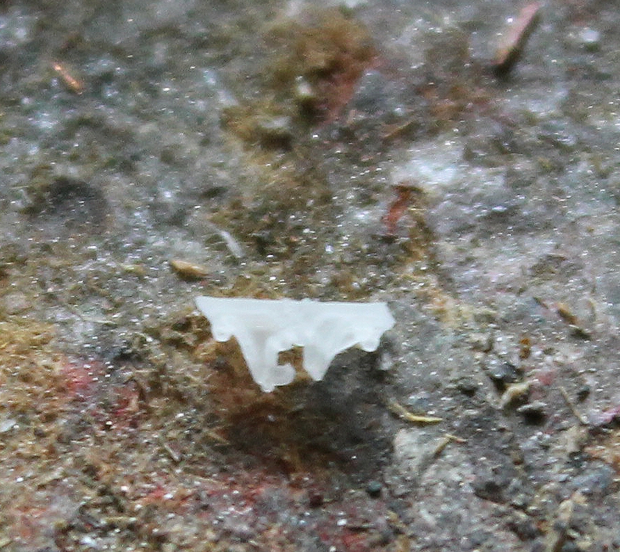
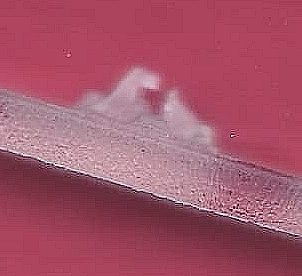
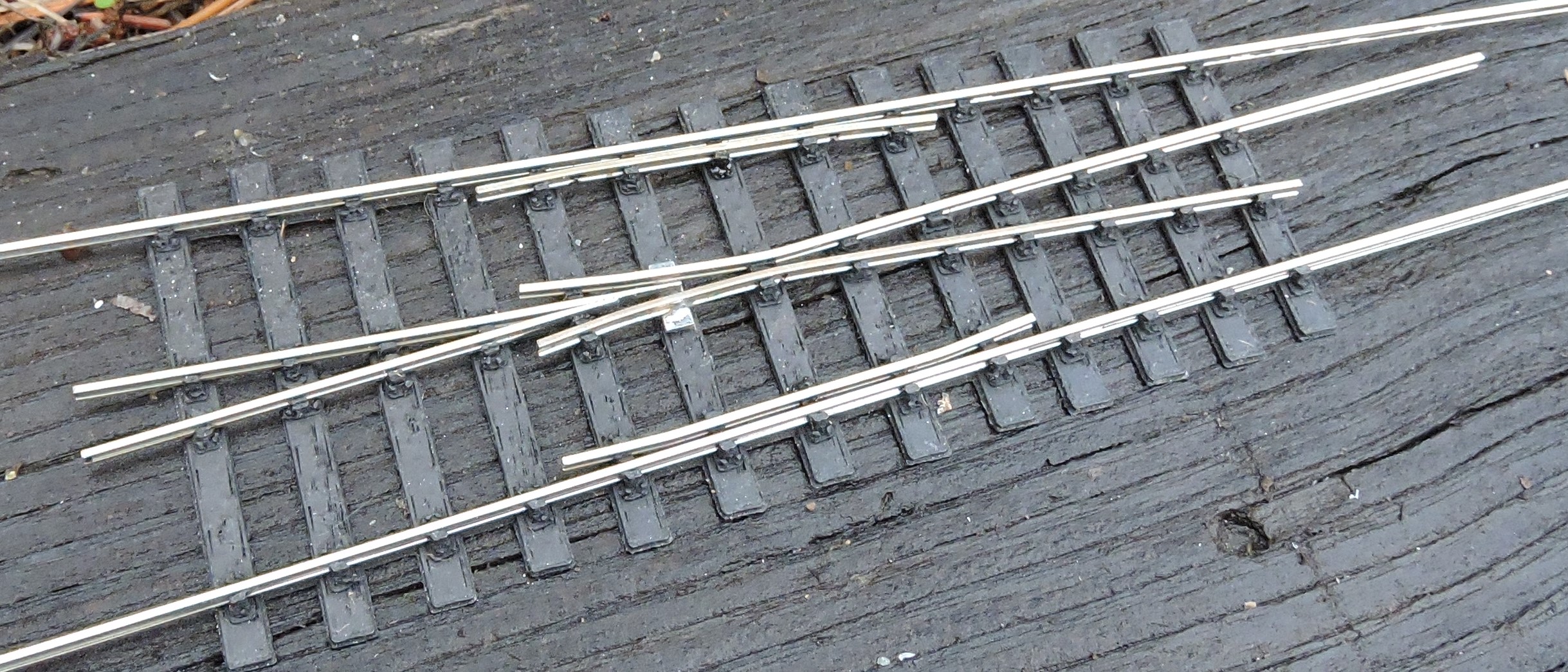
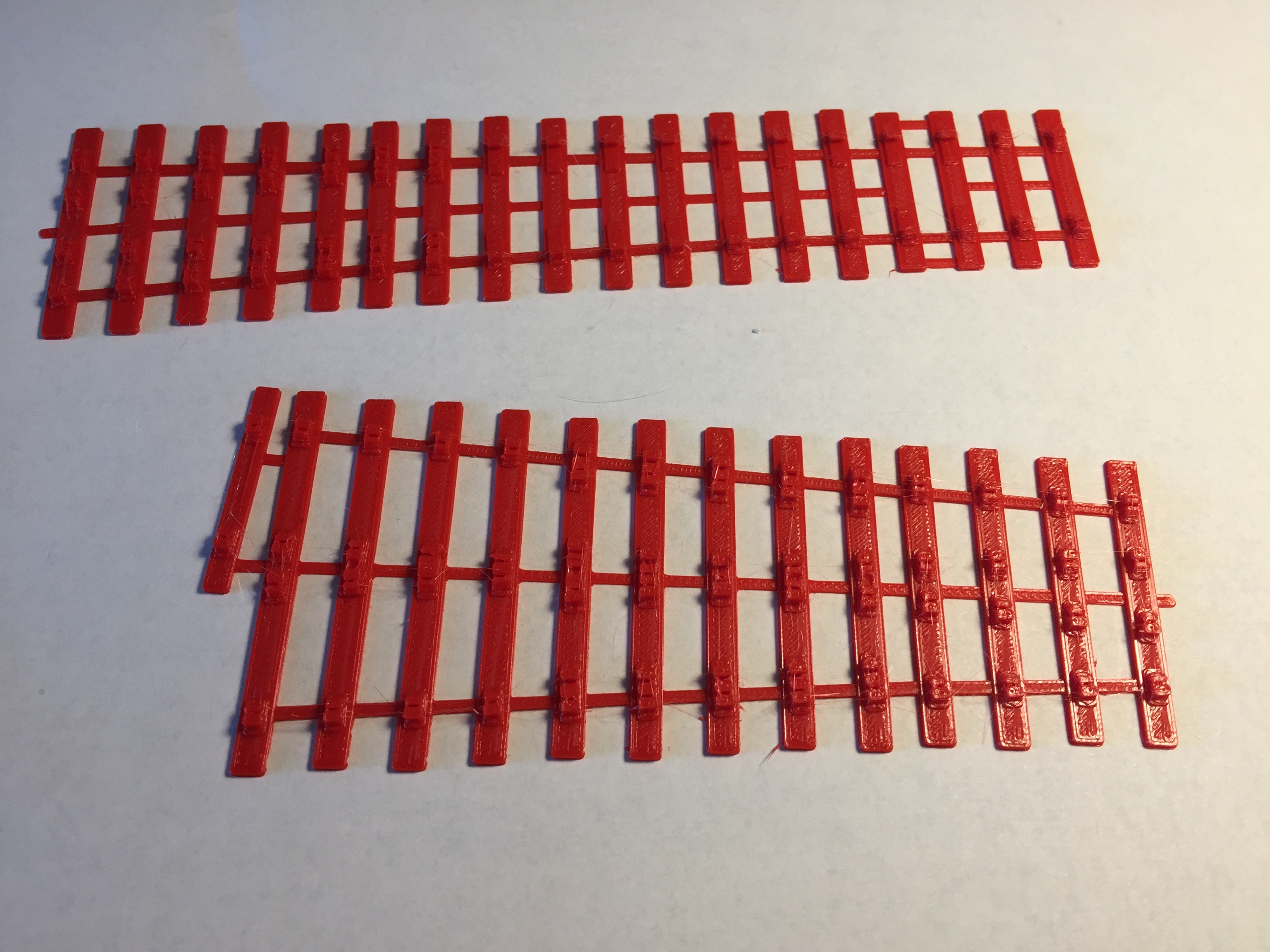
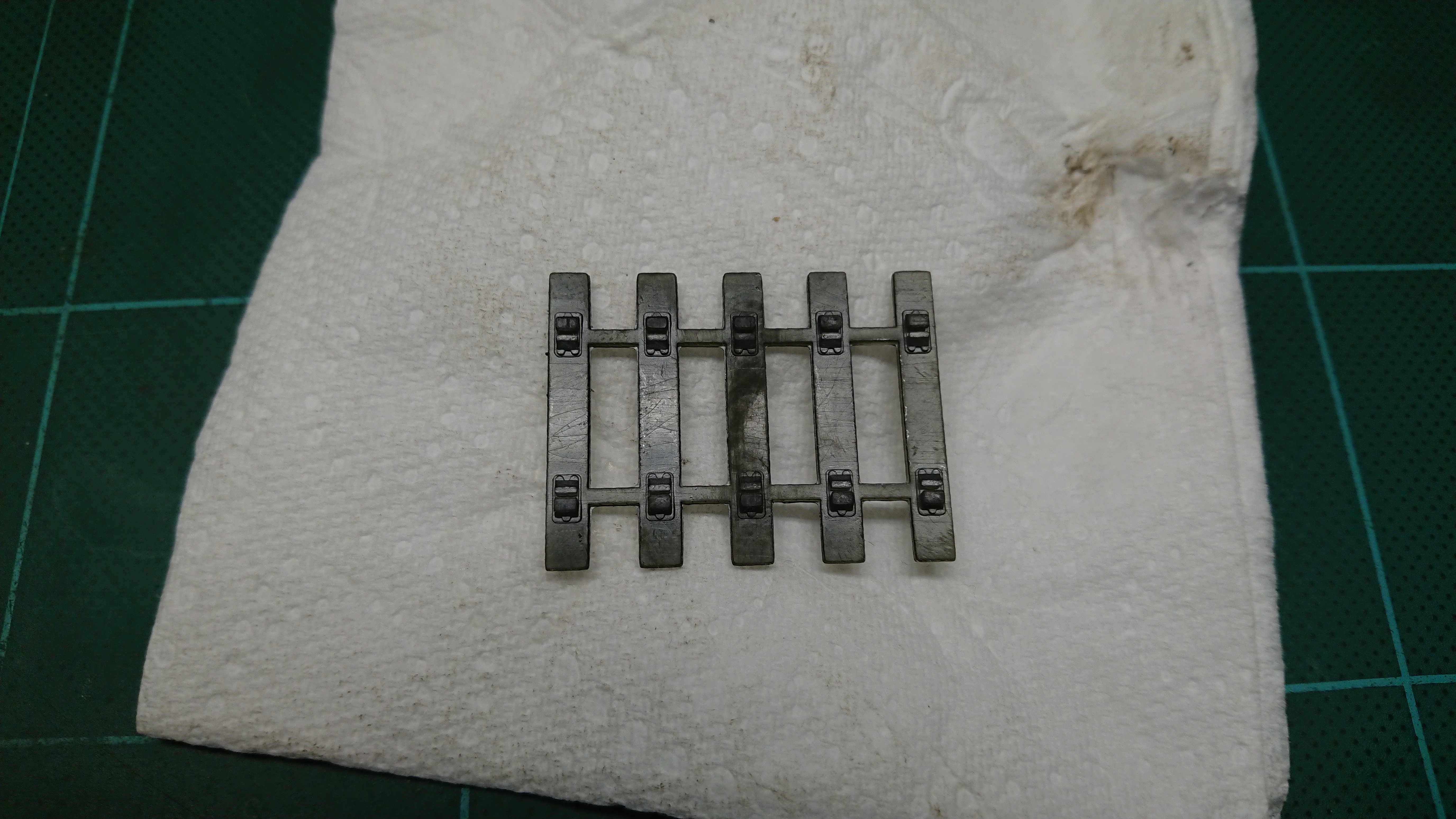
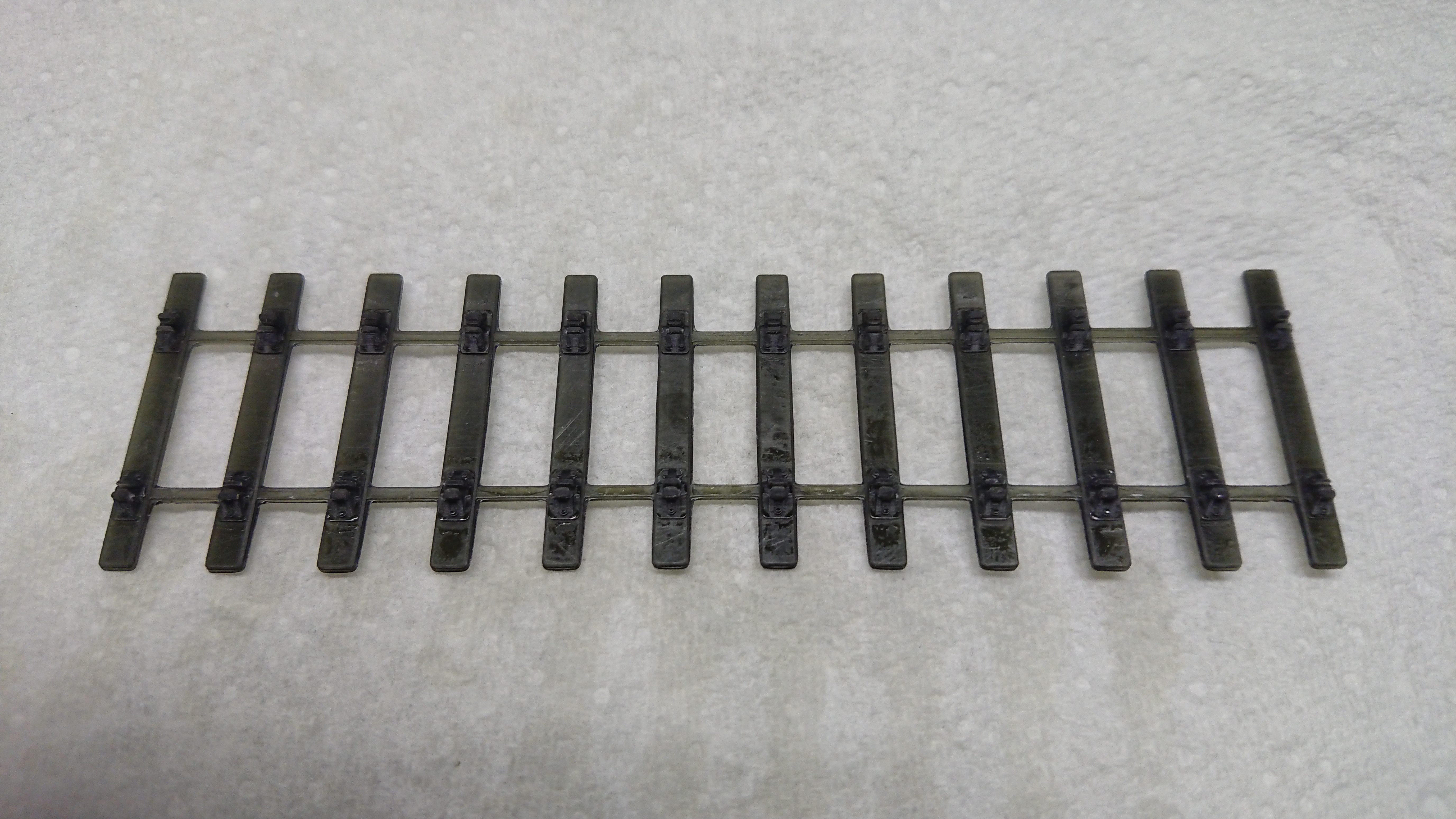
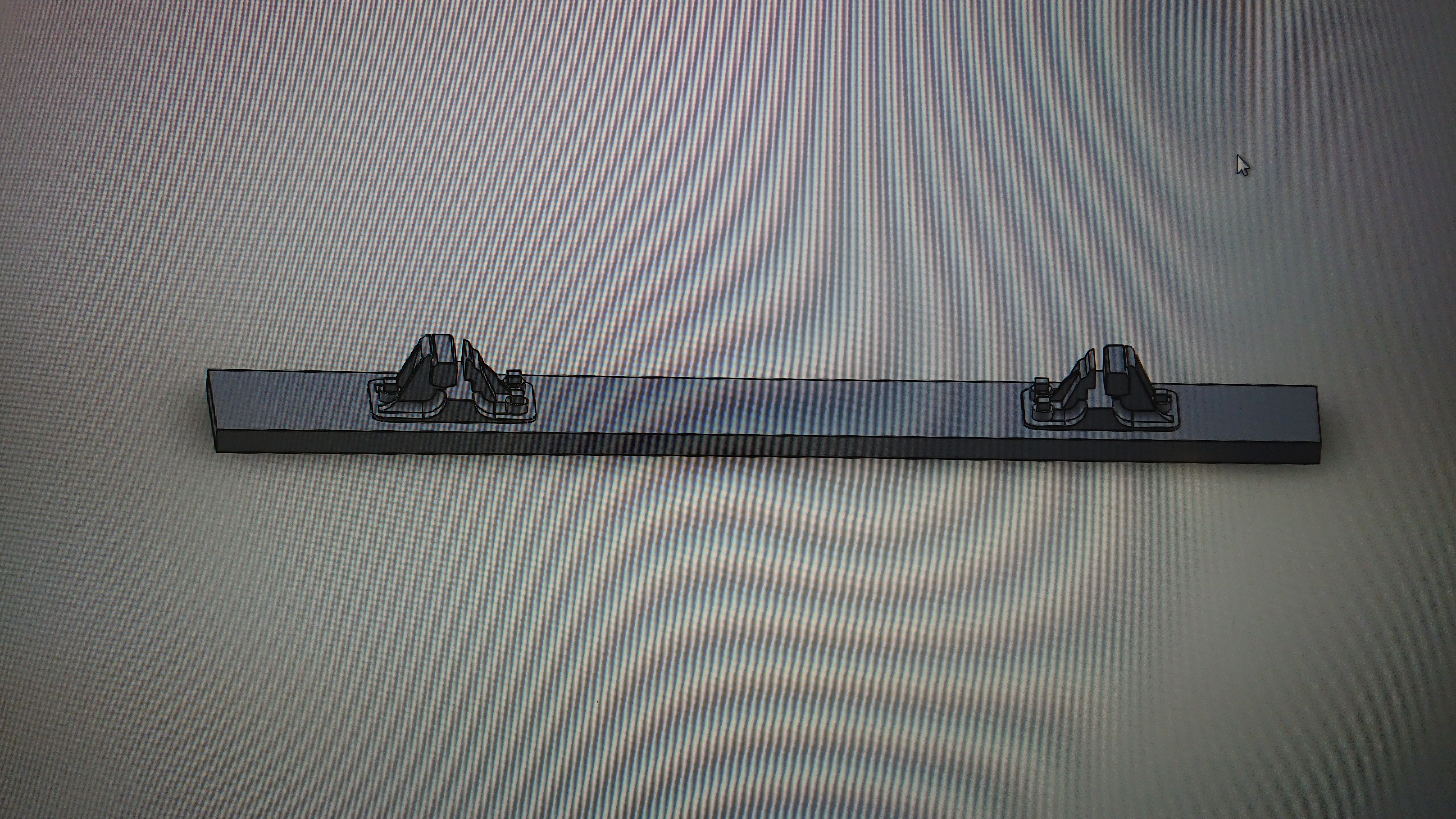
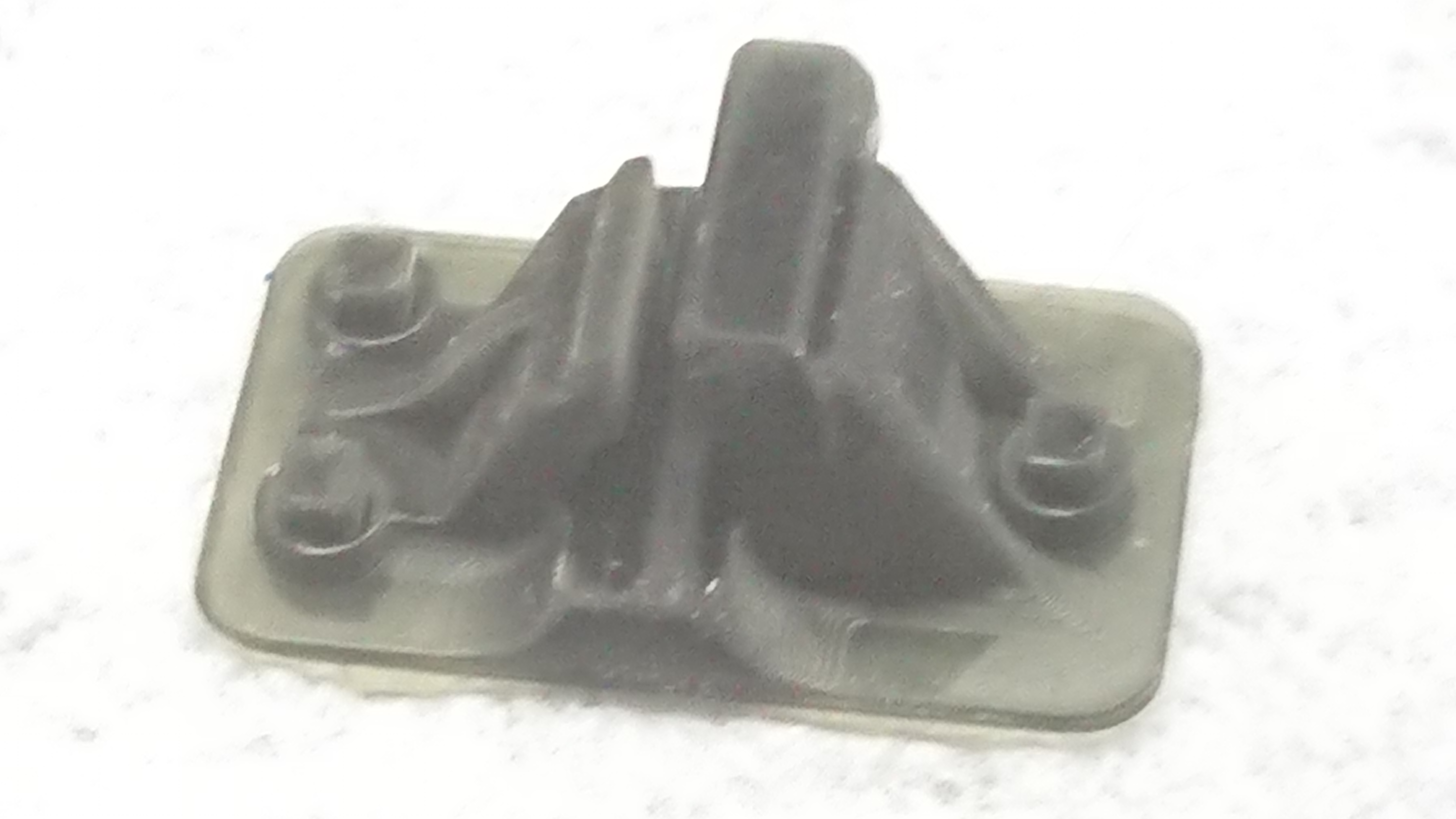
| Please read this important note about copyright: Unless stated otherwise, all the files submitted to this web site are copyright and the property of the respective contributor. You are welcome to use them for your own personal non-commercial purposes, and in your messages on this web site. If you want to publish any of this material elsewhere or use it commercially, you must first obtain the owner's permission to do so. |