Templot Club forums powered for Martin Wynne by XenForo :

TEMPLOT 3D PLUG TRACK - To get up to speed with this experimental project click here.   To watch an introductory video click here.   See the User Guide at Bexhill West.

  • The Plug Track functions are experimental and still being developed. Some of the earlier pages of this topic are now out-of-date.

    For an updated overview of this project see this topic.   For some practical modelling aspects of using Plug Track see Building 3D Track.

    The assumption is that you have your own machines on which to experiment, or helpful friends with machines. Please do not send Templot files to commercial laser cutting or 3D printing firms while this project is still experimental, because the results are unpredictable and possibly wasteful.

    Some pages of this and other topics include contributions from members who are creating and posting their own CAD designs for 3D printing and laser-cutting. Do not confuse them with Templot's own exported CAD files. All files derived from Templot are © Martin Wynne.
  • The Plug Track functions are experimental and still being developed.

    For an updated overview of this project see this topic.   For some practical modelling aspects of using Plug Track see Building 3D Track.

    The assumption is that you have your own machines on which to experiment, or helpful friends with machines. Please do not send Templot files to commercial laser cutting or 3D printing firms while this project is still experimental, because the results are unpredictable and possibly wasteful.

    Some pages of this and other topics include contributions from members who are creating and posting their own CAD designs for 3D printing and laser-cutting. Do not confuse them with Templot's own exported CAD files. All files derived from Templot are © Martin Wynne.

A 2-D Kerf corrected DXF file for lasercut

Quick reply >

Frank

Member
Location
Netherlands
Hi Martin,

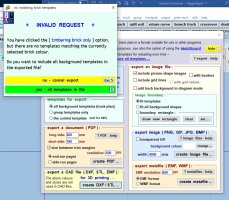
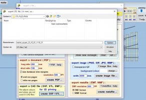
To use lasercutted timbers I have created a DXF file and imported the DXF file in Inkscape to do some post processing and to generate the files/format required by the laser cut factory. I see from the Templot export DXF form that Templot has some KERF implementation when I am right. Can this be used for KERF compensation for timbering in 2D? If so, how can I do this and what settings do I have to make in order to get Kerf compensation working? I see a lot of forum discussions (especially about chair generation in 3-D) but no documentation yet about something like KERF compensation probably because of the experimental character yet? Evenso I see some implementation about sprues? to catch timbers in a certain framework, also usable for laser cutting, I think. Here a bit the same question: is this in any way usable? If not, I have to find my own solution how to solve these issues in i.e. Inkscape. Any help/comment about these subjects is welcome! Thanks as always!

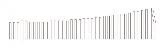
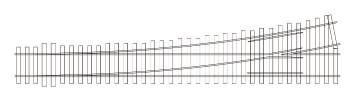
Attached the timbering & timbering+rails of a simple turnout imported by DXF in Inkscape.

Best regards,
Frank
 

Attachments

  • Timbering.JPG
    Timbering.JPG
    24.2 KB · Views: 45
  • Timbering_Rails.JPG
    Timbering_Rails.JPG
    30 KB · Views: 43
_______________
message ref: 8043
_______________
message ref: 8047
Hi Frank,

Martin has already added kerf options.
Once you have invoked Export, and pressed [timbers only] radio button, click on the Layers tab to get:-
1696010739794.png

pressing timbers only has blanked out some of the "layers" that relate to chairs, but you can see there are a couple of layers that have (kerf) in brackets. Now I will perform an export and open in Inkscape.
I then clicked on Layers, Layers and Objects to get the list of layers that Martin has exported on the right hand side>
1696011154833.png

You probably dont want all of these layers, but I exported them all just to show the range of layers that Martin has provided for us.
If you dont want to export a layer just set its colour to blank on the Templot export screen.

The important layers for laser cutting are KERFSOCK and KERFTIMB.

More help to follow when I have time, but this might get you started.
Steve
 
_______________
message ref: 8054
Here is a close up view with a lot of the superfluous layers hidden (the ones with eyelash symbol on the right)
1696013374032.png

What you can see is the TIMBOUTL in brown, and the KERFTIMB layer in green showing the fractional differerence.
Similarly CHSOCKET is grey, and KERFSOCK is blue.

If the timber was cut using the brown lines, it would result in a timber 3.80mm wide assuming a laser kerf of 0.2mm.
Using the green lines results in the correct 4mm wide timber, again assuming a 0.2mm laser kerf.

This is with the default kerf set by Martin of 0.2mm.
Martin has provided a Kerf tab on the DXF export screen with buttons for 2-D cutter kerf and a seprate button for Nibs & Snibs.
The bureau I have used in the past use GREEN lines for outside cut, and blue lines for inside cut.
They cut the blue lines first, then the green lines, to give the best results.
This is because if the TIMBKERF (green) is cut first, there is the chance that the timbers can move around resulting in inaccurate positioning of the KERFSOCK (blue) cuts.
So Blue cuts first (so called inner cuts) then Green cuts next (so called outer cuts)
The laser nibs are also included in the TIMBKERF layer. If you dont want these then untick the "[] end nibs" box on the Templot DXF export layer screen:-
1696014130367.png

Here I have set the export to only output "Chair sockets (kerf)" in blue and "timber outlines (kerf)" in green as that is all I wanted.

Inkscape is a great tool for VIEWING the 2-D DXF file expotred from Templot, as you can easily see all the different layers you have exported and hide them at will.

If you have any questions or want a step by step guide to performing something in Inkscape just let me know.

Prettig weekend
Steve

Tip in Inkscape <ctrl-d> means duplicate a selection. The duplicate can then be moved. All the layers are kept, whereas Copy <ctrl-c> and Paste <ctrl-v> moves all the bits of the selection into whatever is your current layer, not what we want.
 
_______________
message ref: 8058
Last edited:
Hi,
I can't reply right now. But I'll happily add to what has been written above some more tomorrow.

It would be help to find out what 'kerf' the laser cutting company aim for. Typically it is 0.2mm or thereabouts.

Best wishes,

James
 
_______________
message ref: 8060
James,

I commissioned some laser cutting, during the lockdown, after several attempts at getting the items accurately cut, I worked out that his laser cutter had a 0.2mm kerf, after that I made that allowance and all subsequent items were cut to the correct finished dimensions.
 
_______________
message ref: 8061
That is why the default laser cutting kerf in Templot is set to 0.2mm.
If your bureau has a different kerf setting it is easy to amend the kerf parameter that Marti has provided for us.
See the "kerf" tab on the export screen.

Steve
 
_______________
message ref: 8063
Hi Steve, James and Phil,

Many thanks for the reply! I will read all comment carefully and will do some exercises. I think this subject will keep me off the street for a while ;). The laser cut bureau I was planned to use is https://snijlab.nl/ in the Netherlands. They say on their website that 0.2mm is a good choice for the kerf.

Best regards,
Frank
 
_______________
message ref: 8064
That is why the default laser cutting kerf in Templot is set to 0.2mm.
If your bureau has a different kerf setting it is easy to amend the kerf parameter that Marti has provided for us.
See the "kerf" tab on the export screen.

Steve
@Steve_Cornford

Hi Steve,

It's important to clarify the difference between kerf width and kerf offset.

The kerf width is the width of the slot made by the laser beam. The default in Templot is 0.2mm.

The kerf offset is half of that, i.e. 0.1mm. This is the amount by which the cutter is moved away from the outline of the finished part. This is how the blue and green lines in Templot are calculated.

I don't know which of these dimensions the cutting firms refer to, and whether they expect an adjustment to have been already applied to the files they receive, or whether they make their own adjustment based on the actual machines they are using.

It seems important to get all this fully clarified from the start, if you are not using your own laser cutter.

cheers,

Martin.
 
_______________
message ref: 8066
Hi Martin,
Yes I agree.
The kerf offset is always half the kerf.
Laser bureau usually refer to the kerf, not the offset.

The kerf can vary by material and thickness.
I think Templot just needs one parameter kerf and then you halve it to adjust the position of the line forming each side of the rectangles you are producing, just as you are now .
Steve
 
_______________
message ref: 8067
Hi Steve,

I have done a new run with same DXF layer form settings as in your answer. When I press the green -Export DXF file- button I get a message: Invalid Request (see the attached file). It looks that something is maybe undefined in my setup?

When I open the DXF file in Inkscape I see that layers like KERFSOCK & TIMBKERF etc. are completely empty. Have you any idea what this might cause?

Thanks!

Best regards,
Frank
 

Attachments

  • InvalidRequest.JPG
    InvalidRequest.JPG
    155.9 KB · Views: 45
_______________
message ref: 8082
@Frank

Hi Frank,

Assuming you have some background templates (you can't export the control template), make sure you have clicked all these:


dxf_old.png


Please don't copy or re-use this screenshot. It will be all-change and out-of-date within 24 hours. Thanks.

cheers,

Martin.
 
_______________
message ref: 8083
Goodmorning Martin,

Thanks for the 241c update. I just tryed to make a new DXF generation run. In the export form I set: timbers only - laser 2D (new 241c). When I press the green export DXF/STL file I get the following: see image. So it wants to generate STL where I had expected DXF. Do I something wrong? How can I generate a DXF?

Best regards,
Frank
 

Attachments

  • 241c_STL_window.JPG
    241c_STL_window.JPG
    116 KB · Views: 45
_______________
message ref: 8095
Goodmorning Martin,

Thanks for the 241c update. I just tryed to make a new DXF generation run. In the export form I set: timbers only - laser 2D (new 241c). When I press the green export DXF/STL file I get the following: see image. So it wants to generate STL where I had expected DXF. Do I something wrong? How can I generate a DXF?

Best regards,
Frank
@Frank

Hi Frank,

I'm very sorry. I thought I had tested everything, and obviously I hadn't. :(

A fix in 241d will be on the server in an hour or two.

cheers,

Martin.
 
_______________
message ref: 8097
@Frank

Hi Frank,

For a temporary fix, do this:

Click show settings button at top of dialog, then:


fix_241c.png


Don't click the 2D timbers button.

1. Click the 3D timbers button. 2. Click the 2-D option button. 3. Export should be ok.

I will get a proper update done later today.

Sorry again.

Martin.
 
_______________
message ref: 8101
@Frank

Hi Frank,

Templot update 241d is now on the server, with a fix for this bug.

Restart Templot to update.

Sorry for the trouble.

cheers,

Martin.
 
_______________
message ref: 8102
Hi Martin and Steve,

In v241d the flow to generate DXF works fine again. The only issue is that the KERFTIMB & KERFSOCK layers remain empty for some reason (NO data generated). To check if the DXF is working at all, I added colours for the rails and timber outlines. The data for these layers is generated and visible when you readin the DXF into Inkscape.

I saw that in the storage box there is a brick tickmark where you can set the relation between the colour and the actual stored template as it looks to me. I made a run with the tickmark enabled but same result: no difference & layers still empty. Have you any idea what might cause this problem?

I have attached my BOX file including a simple turnout for testing.
Thanks in advance to look into!

Best regards,
Frank
 

Attachments

  • swg_dgv_2023.box
    37.8 KB · Views: 41
_______________
message ref: 8111
Hi Frank,

Your box file contains 3 templates, all for Flat Bottom rail.

What are you hoping to achieve?

Plugtrack does not cater for Flat Bottom rail.

What chair fixings are you hoping to use?

Steve
 
_______________
message ref: 8113
@Frank

Hi Frank,

As Steve suggested, to see kerf lines and sockets in the DXF you need to switch on experimental chairing for the control template, and then store it as a background template:


exp_chairing_3.png


However, you won't see any sockets for the switch section because you have set a flat-bottom switch. Flat bottom track uses baseplates instead of bullhead track chair castings. At present plug track is only working for bullhead track with chairs. I'm hoping that one day it will be possible to do flat-bottom, but it is a long way off with so much still to do for bullhead.

cheers,

Martin.
 
_______________
message ref: 8114
Hi Martin & Steve,

When set -experimental chairing- there is something more working, I see. Until now no difference w.r.t. the DXF but I have to play first with some options and parameters, I think, and maybe read through the chairing forum discussions. A bit overwhelming this experimental flow!

Untill now, I was not aware that the flow only worked for bullhead rails and not for FB rails what is a pitty because I am more oriënted on German railroad. The building method I wanted to use is more to do the design work in Templot and to do the build work as can be seen at i.e. https://www.weichen-walter.de/. Therefore in my case I wasn't plan to use the 3-D chairing functionality/part at this moment, but for the timbering, if possible, I do need the 2-D laser cut functionality in order I can make KERF compensated parts and templates. I hope that using the 2-D laser cut flow is still possible because all needed functionality is in the base available in Templot. I hope the 2-D laser cut & 3-D flow are therefore not too intertwined. Alternative is that I do some post-processing in Inkscape in case Templot is not supporting something. If you have any tips/ideas how it can be done in Templot, please let me know?

Best regards,
Frank
 
_______________
message ref: 8140
Hi Martin & Steve,

When set -experimental chairing- there is something more working, I see. Until now no difference w.r.t. the DXF but I have to play first with some options and parameters, I think, and maybe read through the chairing forum discussions. A bit overwhelming this experimental flow!

Untill now, I was not aware that the flow only worked for bullhead rails and not for FB rails what is a pitty because I am more oriënted on German railroad. The building method I wanted to use is more to do the design work in Templot and to do the build work as can be seen at i.e. https://www.weichen-walter.de/. Therefore in my case I wasn't plan to use the 3-D chairing functionality/part at this moment, but for the timbering, if possible, I do need the 2-D laser cut functionality in order I can make KERF compensated parts and templates. I hope that using the 2-D laser cut flow is still possible because all needed functionality is in the base available in Templot. I hope the 2-D laser cut & 3-D flow are therefore not too intertwined. Alternative is that I do some post-processing in Inkscape in case Templot is not supporting something. If you have any tips/ideas how it can be done in Templot, please let me know?

Best regards,
Frank
@Frank @James Walters

Hi Frank,

Timber outlines have been available in 2D DXF output from Templot for 25 years -- before we had 3D printing or home laser cutters!

Nowadays we also have the kerfs, nibs and snibs to make it more practical for laser cutting.

If you want chair sockets too, it gets more problematic because Templot needs to know what goes in them to set the size. It doesn't know anything about German track, or in fact anything other than REA bullhead.

To export only the kerf lines for laser-cutting, rather than the actual timber outline, you need to set experimental chairing on the template(s). That means changing the setting, and then storing the template.

Then click these:

old_dxf1.png


old_dxf2.png


Then export the DXF file, and the result should be:

old_dxf3.png


I hope this helps. If not please ask again. @James Walters can help in setting practical sizes for the nibs and snibs.

I'm sorry if we have been a bit slow in grasping what you are wanting to do.

cheers,

Martin.
 
_______________
message ref: 8141
Hi Frank,
I looked at the weichen-walter website, and it looked to me as if most of the trackwork featured flat bottomed rail soldered to copper clad timbers.
Is that what you plan to do?

Steve
 
_______________
message ref: 8143
Hi Steve, you are right! They use copper clad timbers for those timbers who are essential to make a stable and solid construction or in some cases for electrical connections. The remaining timbers etc. are laser cutted stuff (wood). The copper clad timbers are soldered and the chairs are cutted from normal rail pieces and glued. Finally it is painted and they have a great solution for the 3rd rail in the middle for them who need that. This is the basic. Besides that in recent years there are some variants to make it more nicer. They make it mainly for H0, N and Z. These gauges are that small that the glued chairs are not a too big problem. There is another website: Fast Tracks (https://handlaidtrack.com/ - its US or Canadian I thought) doing something similar with all kind of pre-fabricated templates. But to make more natural turnout constructions for me Templot is the only tool who can design that. That's why I am really enthousiastic about it!

Best regards,
Frank
 
_______________
message ref: 8145
Hi Steve,
The models I have are from 1950 onwards till say 1980/1990. That means the track begins some what earlier say the period from the twenties onwards. This is for the track the period: DRG (Deutschen Reichsbahn Gesellschhaft - twenties onwards), DB (Deutschen Bundesbahn - sixties onwards) till say eighties/nineties. In that period the profile nearly always was FB, see also the head and foot profile width in the tables on: https://de.wikipedia.org/wiki/Schiene_(Schienenverkehr). It gives you a good indication. Also in the Netherlands was always a lot of FB track as far as I know. Maybe FB track is typical western european continent, I don't know. Maybe there was at some places BH track but not widely spread. So FB was the first what came up in me to use and not BH.

Best regards
Frank
 
_______________
message ref: 8153
Hi Martin,

Yesterday evening I did a run with the latest settings you suggested. Besides that I have set also some other options just to see what it does and what data is generated in the DXF. As you can see there is much more data available, incl. for the KERF compensated timbers. Now I can figure out the settings so I get only what I need. Thanks so far putting me a bit on track again!

WhatDataGenerated.JPG


Best regards,
Frank
 
_______________
message ref: 8179
Hi Martin,

I have a question about the “experimental chairs” mode I use to enable the kerf functionality. See also the attached images.

When I start with a configuration as in control_tmpl image (turnout with perpendicular straight timber) and I enable the -experimental chairs mode, the kerf compensation looks correct calculated (see images) but the location of most timbers is changed and rotated. Ofcourse this is needed for the chair placement but not wanted for 2-D laser cut. Is there an option to prevent the rotation and keep the timbers in position? Or any other way?

control_tmpl.JPG


control_tmpl_and_settings.JPG


store_and_background_tmpl.JPG


rotated_timbers.JPG


Best regards,
Frank
 
_______________
message ref: 8259
Hi Frank,

Suggest you attach your box file when asking questions as this will give us the detail of your templates.

I can only assume that you have created a turnout with a crossing angle of 1:6 or less.
For 1:6 or below. When you switch on Experimental chairing Templot automatically sets timbering to the equivalent of "equalised incremental" otherwise the chairs would be too close the the edge of the timbers. However when you go to the meu Real > Timbering it still shows as square-on.
1696626205512.png

Steve
 
_______________
message ref: 8260
Last edited:
Hi Steve,

That is correct! The angle is small 1:4,7 (12 degrees) !
Hereby the .box file. Thanks for looking into!

Best regards,
Frank
 

Attachments

  • swg_dgv_2023.box
    37.8 KB · Views: 53
_______________
message ref: 8261
Tight curves in Germany!

Why are you worried about this?

Is it because you want to get the grain of the ply in the longest plane of the timber?

If you are using a mix of Copperclad and ply, just buy the ply timbers as long lengths already cut to width and cut them to length yourself.

Print your track design to paper, then stick double sided tape over it, and cut timbers to length and stick down onto the paper.
ditto with the copperclad.
Then solder your flat-bottom rail onto the copperclad timbers using the printed template as a guide, then stick your plastic chairs onto the ply timbers as portrayed in the website you linked to.

This is just a guess on your construction technique, but perhaps you could describe your plans in more detail.

Are you planning on mixing copper clad and ply timbers?

Steve
 
_______________
message ref: 8262
@Steve_Cornford @Frank

Hi Steve, Frank,

With experimental chairing switched on, equalized timbers are forced for V-crossings below 1:6 for press-fit sockets, and below 1:7 for clip-fit and snap fit sockets.

At present there is no way of switching this off, but I intend to provide one, and should have done. I forgot to consider that anyone would want the kerf lines without the sockets. Sorry about that.

Frank, why do you want square-on timbering on such a short turnout as 1:4.7 ? It's not prototypical because the prototype would have exactly the same problem -- chairs overlapping the timbers, and chair screws too close to the edge. It would have required expensive 14" or even 16" timbers, and that's not justified for 1:4.7 because such short turnouts would be found only in yards and sidings. I suggest you follow the prototype and build it with equalized timbering. :)

cheers,

Martin.
 
_______________
message ref: 8263
@Frank

Hi Frank,

I have added another tick box:

unchaired_kerf.png


You can then get your timber kerf lines without needing to set experimental chairing. Which means equalized timbers won't be forced.

This will be off by default, otherwise it increases memory consumption unnecessarily while track-planning without chairing.

Will be in 241e. I will try to get it released later today.

A template-specific option not to allow forced equalizing will be later. It will require a version bump to 242a.

cheers,

Martin.
 
_______________
message ref: 8264
Hi Martin, Steve,

Martin thanks for adding the options for 241e and 242a. It will give some more flexibility to fix the problem! I will pay some more attention to the equalization of the timbering. I overlooked that!

Maybe you think why is he using such long straight timbers in a single turnout? Well what I forgot to tell was that the turnout in my thoughts was planned for a scissors crossover. When I saw all those rotated timbers I thought: This will never going to work in this way as that the 3-D socket functionality (which causes I think the rotations) is not needed for a 2-D laser cut approach.

The construction I planned to use is a mix from copper clad and ply timber. The ply timbers (maybe partly connected in a frame or not) I want to make by using the laser cut flow. To produce these parts the kerf compensation is important.

I hope this clearifies a bit.

Best regards,
Frank
 
_______________
message ref: 8271
Back
Top