@James Walters
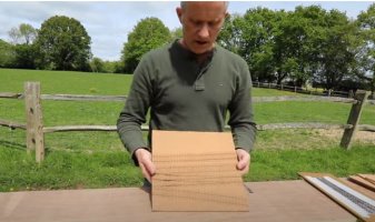
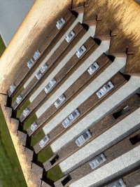
I have now made a few chairs on the Geeetech Alkaid printer, and at the second attempt they are excellent and identical with ones from the Mars.
")
I can't see any difference. Possibly the loose-jaw slots are a fraction undersize, but that can be changed in the settings.
For the first attempt I used the recommended Alkaid settings with 2-second exposure. It was obviously insufficient -- the rafts didn't stick properly to the build plate and the finished chairs felt soft and sticky, even after washing. 10 minutes in the UV unit cured that, and they are now just about usable, if I'm desperate.
So I changed to using all the same settings as on the Mars, except for increasing the exposure time to 3 seconds. The results are fine, and mean this inexpensive little printer is great for plug track, and probably a lot else. (Using Elegoo ABS-Like grey resin, I haven't tried any others.)
There are very few niggles resulting from the cost-saving -- the USB socket is at the back, which is not very convenient. It's also upside down. It's there because it is part of the control board which is mounted there for the power socket and on-off switch. But I found a short USB extension cable which can be left on there, so that problem is solved. I took one look at the plate levelling cap screws and decided they needed washers under them. So that's what they got. Other than that there is nothing really to complain about, it's a very well-made no-frills small resin printer. I will leave James to do a full review and video, and try it for stuff other than plug track.
Not forgetting the little tweezers. I know what I will be using them for, but as to what they are intended for I can't find any explanation.
cheers,
Martin.
 Search