Templot Club forums powered for Martin Wynne by XenForo :

TEMPLOT 3D PLUG TRACK - To get up to speed with this experimental project click here.   To watch an introductory video click here.   See the User Guide at Bexhill West.

     Templot5 - To join this open-source project on GitHub click here.  For news of the latest on-going developments click here.  Templot5 is now included with Templot2 - download.

  • The Plug Track functions are experimental and still being developed. Some of the earlier pages of this topic are now out-of-date.

    For an updated overview of this project see this topic.   For some practical modelling aspects of using Plug Track see Building 3D Track.

    The assumption is that you have your own machines on which to experiment, or helpful friends with machines. Please do not send Templot files to commercial laser cutting or 3D printing firms while this project is still experimental, because the results are unpredictable and possibly wasteful.

    Some pages of this and other topics include contributions from members who are creating and posting their own CAD designs for 3D printing and laser-cutting. Do not confuse them with Templot's own exported CAD files. All files derived from Templot are © Martin Wynne.
  • The Plug Track functions are experimental and still being developed.

    For an updated overview of this project see this topic.   For some practical modelling aspects of using Plug Track see Building 3D Track.

    The assumption is that you have your own machines on which to experiment, or helpful friends with machines. Please do not send Templot files to commercial laser cutting or 3D printing firms while this project is still experimental, because the results are unpredictable and possibly wasteful.

    Some pages of this and other topics include contributions from members who are creating and posting their own CAD designs for 3D printing and laser-cutting. Do not confuse them with Templot's own exported CAD files. All files derived from Templot are © Martin Wynne.

Experimental 3D plug track - up to version 244c

Quick reply >

Martin Wynne

Admin
Location
West of the Severn UK
Info
.
Enjoy using Templot?
Thanks.

Please do not send requests for help direct to me via email.

Post your questions on the forum where everyone can see them and make
helpful replies.
.
edit April 2024: This is a very long topic of 2,500 posts, documenting progress of the Templot plug track project from its beginnings in 2021 up to March 2024 - i.e up to program version 244c.

The early posts in this topic do not represent the current state of the project, but do explain some basic concepts which may not be explained again later.

For up-to-date information, see this later topic: https://85a.uk/templot/club/index.php?threads/891/

The original topic begins below.


14 March 2021

This is a continuation from several previous topics about 3D printed track. Having adopted the name Plug Track to describe these experiments, I have started a new forum section to discuss them.

If you want to receive emails from this new Plug Track section of the forum, you will need to update your forum Watch settings accordingly. For how to do that, go to:

https://85a.uk/templot/archive/topics/topic_3839.php#p31676


Please be aware that Plug Track is still extremely experimental and in continuing development.

There are various options you can now tinker about with, but very little which is as yet actually usable on your layout.


Very pleased with the first results from the Elegoo printer. :)

The CAD rendering:

resin_chairs1.png

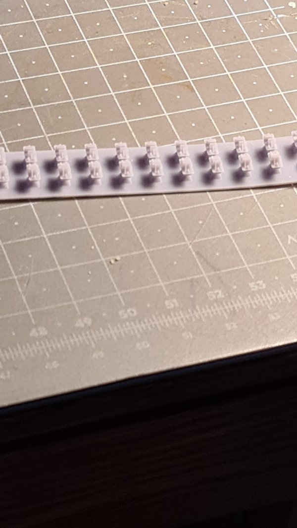
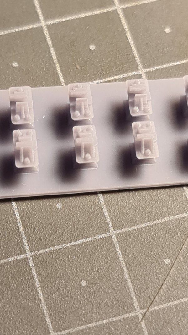
Straight off the printer -- 4mm scale (difficult to photograph without any paint):

resin_chairs2.jpg


resin_chairs3.jpg


resin_chairs4.jpg


resin_chairs5.jpg


resin_chairs6.jpg


cheers,

Martin.
 
_______________
message ref: 816
And the verdict is?

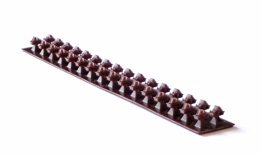
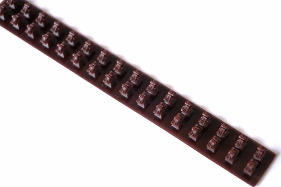
I used the bog-standard default slicing settings for the Mars 2P in the Chitubox software. I was tempted to try changing things for finer detail, but decided to leave that until I know what I'm doing. :) In the event the result was very good, so it was probably a wise decision.

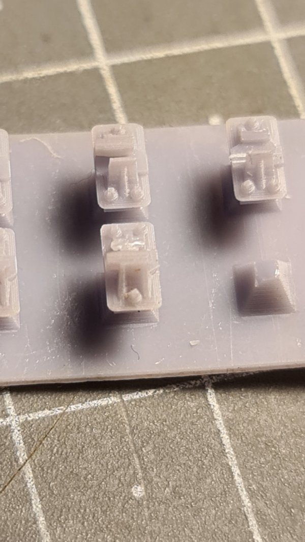
The end 2 chairs in each row failed to print. I got only the support pyramids with no chair on top. But the 3rd chair from the end in each row printed perfectly, and all chairs in between.

* This suggests that the UV illumination is not even, and drops off suddenly at each end of the build area. This probably means that only the middle 80mm square area of the build area can be used for fine-detail models. This may be on my machine only of course (Mars 2P).

* edit: see next post.

I found the missing bits of half-printed chair lurking in the resin, partly stuck to the FEP film, but easily removed. This surely affects the idea of leaving the resin in the tank unfiltered for next time? They would clearly impede the first layer of the next print. So if doing that, it would be important to check that the previous print was fully formed with nothing missing.

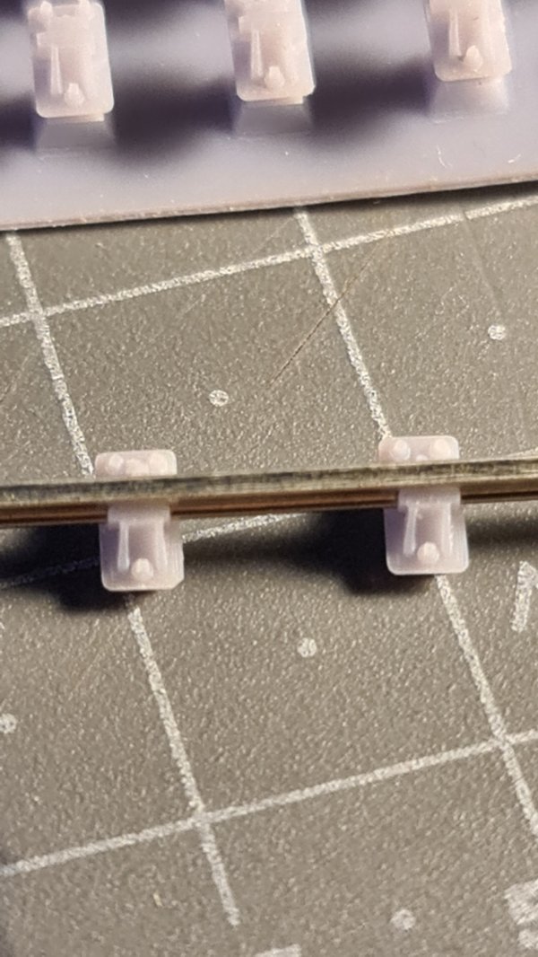
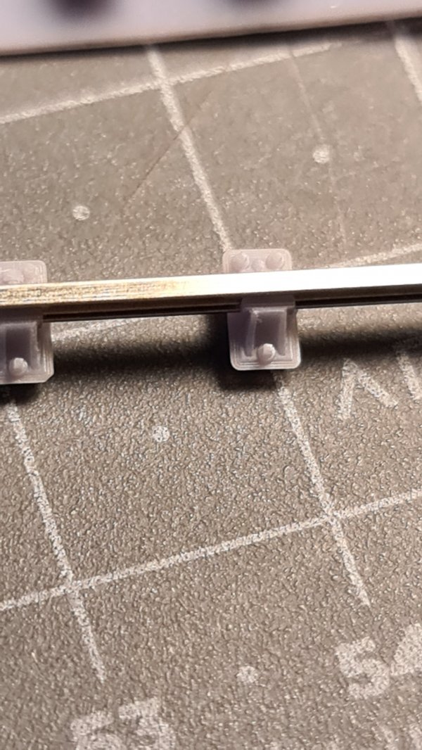
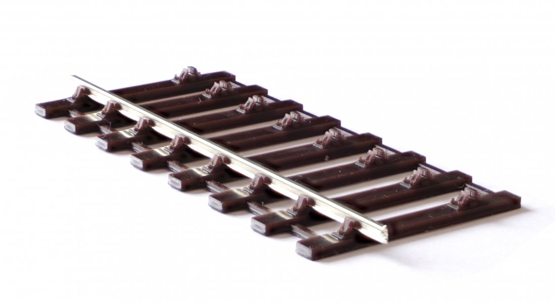
I set the dimensions in Templot to match Exactoscale code 75 steel rail, and it worked out very well. The chairs can be threaded onto the rail without difficulty (much easier than threading Exactoscale moulded chairs), but then hold the rail vertical (as intended) with no wobble or play. As you can see in the photos, there is no infill below the key (this is an option in Templot), so that the rail is held entirely by the key against the rail web as on the prototype, and not by means of the rail foot:

index.php


index.php


The plug under the base of the chair gives it a lot more "heft" than other 4mm chairs (if you can use such a word for such a tiny thing) so that there is no distortion and the chair sits flat after threading (unlike Exactoscale chairs).

Dimensionally there has been about 1-1.5% shrinkage. I don't know where in the process this occurs, but I suspect in curing. The finished sizes are:

chair length: 4.79mm. Prototype 14.5" = 4.83mm (Exactoscale 5.08mm, noticeably larger than scale alongside these).

chair width: 2.64mm. Prototype 8" = 2.67mm (Exactoscale 2.79mm, noticeably larger than scale alongside these).

plug length: 4.12mm. Design 12.5" = 4.17mm.

plug width: 1.97mm. Design 6" = 2.00mm.

Some allowance for the shrinkage may need to be included in the files. On the other hand, the shrinkage on the plug is maybe welcome to ensure a clearance in the sockets. But we don't want too much because they will be setting the gauge. Some final tweaking of the dimensions is likely to be needed.

I'm attaching the .ctb file below for Charles and anyone who wants to try repeating my antics in an Elegoo. But you won't be able to make any actual use of the chairs until we have some timbers with matching sockets.

(This file is ready to use on the Elegoo printer, it is already sliced and ready to go -- just save it onto a USB stick.)

p.s. I'm using the "ABS-like" Elegoo resin. Results with the standard resin may differ. Colour grey, results with other colours may differ.

edit: this file is now 2 years old and out of date -- the plugs are less deep than the current designs, and the dimensions differ. These chairs are unlikely to fit the current sockets very well. See later attached files in this topic for more recent designs. See later pages in this topic for up-to-date information about Plug Track.

cheers,

Martin.
 

Attachments

  • _32_chairs_s1_exacto_rail.ctb
    1.5 MB · Views: 536
_______________
message ref: 838
I would be very grateful if you or any one else could let me have some stl files of chairs/sleepers etc to try out and experiment with print settings.
I'm modelling in 4-SF.

Hi Charles,

See my previous post for the CTB file of the chairs with plugs, ready for printing.

Here's an STL file which you might like to try. 8 sleepers in 4-SF / 00-SF with S1 chairs for Exactoscale/C&L rail:

stl_for_charles.png


The offset webbing is to indicate which side is MS. it is 1mm square.

I have never printed this, so I've no idea if it is any good. :)

p.s. ignore the message in Chitubox that it is too small. Every single thing I've tried has been allegedly "too small".


cheers,

Martin.
 

Attachments

  • exacto_rail_8_sleepers_4_sf.stl
    2 MB · Views: 414
_______________
message ref: 841
Hi Martin,
I've set the printer up and the first print is excellent. I've attached some photos below.
I'm very pleased with the quality.

20210318_155654.jpg20210318_155705.jpg20210318_155422.jpg20210318_155510.jpg20210318_155607.jpg
I'll have a go at the stl file tomorrow.

Charles
 
_______________
message ref: 857
Hi Martin,
I've set the printer up and the first print is excellent. I've attached some photos below.
I'm very pleased with the quality.

View attachment 643View attachment 644View attachment 645View attachment 646View attachment 648

Charles
Hi Charles,

Those look great! I'm glad you're pleased. :)

Did you get all 32 chairs, or lose some at the ends of the strip?

Your close-up photography is better than mine, and for the first time I can see the square tops and random angle on the chair screw heads. Well on two of them anyway:

charles_chair.jpg


I notice that you've lost one corner of the chair base. That happened to me in handling, too. I will look to thicken it up a fraction. It's prototypical for an occasional chair, but not too many.

I can also see some layering from the slicer on the side of the base. I set the standard 0.05mm Z layers in Chitubox, which matches the X-Y pixel resolution for the UV image. It's possible to go finer for the layers only, some tweaking experiments are called for. On the other hand, the layers will probably vanish under the paint. The chairs are infuriatingly difficult to photograph unpainted, even though the raw resin seems quite a dense grey.

I've been working for the last couple of days on getting a direct STL export from Templot, instead of needing to convert from DXF. It's now beginning to look promising, after a rubbish start.

Thanks for posting your results.

cheers,

Martin.
 
_______________
message ref: 860
I'm pleased to report that Templot can now export 3D files in STL format in addition to DXF:


stl_ex_templot.png


stl_ex_templot_pad.png


This removes one bottleneck from Templot 3D printing which has been bothering me for some time. It's very difficult to find a free or low-cost CAD package which supports 3D DXF files. 3D Crafter seems to be the only one, but it's very clunky and buggy and seemingly no longer being developed. All the others are quite expensive. Now you don't need one.

It's not all good news. As far as I can find the STL format does not support nested blocks. It's a single flat fully exploded file -- unless anyone knows otherwise?

This means that STL file sizes are massively inflated compared with the corresponding DXF file:

The above in DXF: 750 KB
The above in STL: 7900 KB

More than 10 times larger.

Also the STL files from Templot (just like the ones converted from DXF in TurboCAD) are not solid objects ready for slicing. For that they first need to be "repaired" in a mesh editor program, such as this free online tool:

https://www.formware.co/onlinestlrepair (others are available).

The above trackpad shot (EM gauge) shows that full 3D resin printing of complex pointwork is not going to be very practical on a small printer such as the Mars. The purple outline is the effective size of the Mars build plate. A large formation would be a jigsaw of small pieces to be aligned and fitted together.

But I'm not planning to do that. The timbering will be either FDM (filament) printed, or laser cut from plywood. Only the plug-in chairs need to be resin printed, and they can be bunched together in a single print (STL file size permitting). For FDM printing the build area is much larger at 200mm square on my machine, but that still requires some careful planning of jigsaw pieces to create a full pointwork formation.

As you can see, I still have a long way to go. Only the ordinary S1 chairs are finished. The L1 bridge chairs so far have a base and keys, but no chair jaws. All the other special chairs are also unfinished.

But with STL exports done I can now see the way forward to a usable system. Threading chairs one at a time, and then plugging the rail vertically onto a base, has got to be so much easier than feeding the rail into a base from one end. Especially for complex slips and crossings. And with Wayne Kinney's new cast crossings likewise plugged straight onto the base, we should have a new trackbuilding system which anyone can use.

Dream on -- still a long way to go. :)

Martin.
 
_______________
message ref: 885
Thinking about gauge widening and angled chairs on points, would this be dealt with on the sleepers?

Hi Tom,

Yes, the individual chairs will be matched to the standard REA drawings as far as possible. The sockets for them in the timber will determine the angle and position of them, and thus also set the gauge.

I haven't given any thought to gauge widening at this stage -- one thing at a time. :) It could be done as part of the shove timber functions. It can't be set from the turnout size alone, because it depends to what extent they are curved, and in which direction. Also the track standard plays a part -- P4 needs gauge-widening where 00 doesn't. So it's difficult to see it becoming fully automatic.

cheers,

Martin.
 
_______________
message ref: 892
This afternoon's entertainment was to get the chair plugs into the 2D:

plugs_2d.png


I have put a 1/2" break across the plug corners for a clear fit in the sockets. For the bridge chairs I have increased the base overlap, so that the sockets do not get too close to the edge of the timber.

The plugs and screw centres aren't really needed in 2D, but the only way to check that the code is putting every one in the right place is to draw them on the screen.

One more tiny step on what is going to be a long journey.

Martin.
 
_______________
message ref: 909
Hello Martin,
Is there a particular reason why you are using square/rectangular sockets for chair location? Would a round socket allowing them to rotate not enable one to adjust a chairs position indefinitely without restriction? Or am I missing something really obvious?

Hi Trevor,

The angle of a chair on a timber is determined by the turnout geometry, there isn't any option for it to be at some other angle.

The idea is that the timber base is 3D printed, or laser cut from plywood, and the chairs plug straight in to the exact position, requiring no gauges or other adjustments.

But I'm not printing the bases or the chairs -- you are. :)

If you want to edit the DXF or STL files to use round plugs and sockets that's up to you. There will also be options in Templot to change the size of the plugs, or have no plugs, or change the chairs to some other design, or flat-bottom baseplates, or whatever you want.

But don't hold your breath. I have a long way to go, and I'm distracted by other things. It's high time I got the 227a update finished and released, it's got a lot of new stuff in it which some folks are waiting for. On top of that I still have the migration to the new server unfinished, and no archive of the old forum yet ready. Strictly speaking getting the Elegoo printer was a mistake, as it's a fresh distraction and has now added a re-write of the 3D output to the pile of other unfinished stuff I have waiting. Templot is supposed to be my hobby, it's not supposed to feel like work. :) But I will get round to everything in the end.

cheers,

Martin.
 
_______________
message ref: 972
If I might ask, how are you eliminating the rail inclination? Are you leaving the bottom of the rail in the same position and pushing the top out, pushing the bottom in or rotating the rail so the bottom moves in and the top moves out?

Also, are you leaving the base full size or are you reducing its length at all?

Hi Andy,

The rail gauge-face is the datum, and all the chair dimensions have been referenced to scale from there. So I guess that means I have moved the rail foot inwards to bring the rail vertical.

It's a stylised geometrical design, with some intentional changes. For example the key is tapered at both ends for easier threading, and contacts the web fully in its centre only (the prototype key should be wedge shaped). The base edge thickness is increased to avoid damage in handling and allow at least two 0.05mm slicer layers (the scale thickness would be only 0.08mm or 3 thou).

The chair base dimensions are as the drawing, I'm not clear why you think I might have reduced the length?

cheers,

Martin.
 
_______________
message ref: 985
Hi Guys,

It's really nice to see this thread, the work I've seen so far is fantastic!

It certainly reminds me of my last 12 months of the research and challenges in developing my Finetrax Easy Build turnout kits, which use a similar process.

Martin, I printed the STL's you uploaded on my machine, using the same resin mix I use for my Finetrax bases. They also went through the same post processing.

print01.jpgprint02.jpgDSC05623.JPG


Your chairs look great and fit the EMGS bullhead rail well. I did notice the rail leaning 'inwards' a bit, which I believe is because you left the gap underneath the keys.

I'm looking forward to following this thread and contributing where I can as I've got quite a bit of experience on this now ;)

Thanks,
Wayne.
--------------------------
Home of FinetraX Easy Build Turnout Kits - www.britishfinescale.com
 
_______________
message ref: 1828
Last edited:
@Wayne Kinney

Hi Wayne,

Welcome to Templot Club. :)

Good to see you here -- how much of Templot is in your kit designs?

Your prints look good. Can you tell us a bit about your printer and resins? I know you regard it as something of a trade secret.

Filling below the keys, so that the rail foot is firmly located, will be an option in Templot:

dxf_key_fill.png


It's off by default because that's prototypical. It's also possible to "beef up" the chair jaws overscale, to make them stronger. That's likely to be needed in the very small scales, 3mm etc.

The rail I have here (Exactoscale steel bullhead) is standing vertical in the chairs. If yours is leaning it may be due to variations in the rail web section -- if you turn it round does it lean the other way? There will an option to fine-adjust the track gauge for any rail-lean by moving the chair jaws relative to the chair base.

All this is still a work-in-progress. I haven't had a chance to get much done recently -- I want to get back to it soon. :)

cheers,

Martin.
 
_______________
message ref: 1829
Thanks Martin,

I use the 2D DXF's from templot as the basis for the bullhead stuff. I import these into Solidworks, and work from there. I do modify a couple of things from the template, mainly gauge widening around the switch. I also use the exported DXF as the basis for the cast crossings.

Yeah, I don't want to say too much on my chosen machine and resins, but it does use a similar process and to the same resolution and layer height. The output from your machine should be about the same.

I think what you are working towards is amazing, to be able to export a 3D CAD model out of Templot that can be directly 3D printed, it's a fantastic prospect!

Designing my kits is a very tedious affair, having to locate and oriented each chair manually. it does give me much design freedom, however.

After measuring the gauge of your STL I printed, it seems OK anywhere between 16.17 - 16.25mm. Looking again the rail doesn't seem to be leaning as much as I first thought.

I wish I could have a play with the 3D export features you are working on, obviously it's disabled in the current release...
 
_______________
message ref: 1830
I wish I could have a play with the 3D export features you are working on, obviously it's disabled in the current release...
@Wayne Kinney @graeme @Alistair Ward

Hi Wayne,

Yes, I wish you could too! There's still such a long way to go.

I've had the FDM filament printer for a couple of years -- see the previous topics on the old forum. I spent a lot of time trying to FDM print acceptable chairs. They were ok in 7mm scale, if rather fragile, but in 4mm were hopeless. Also very slow of course. Andy B did much better than me.

I then tried the idea of FDM printing ready-chaired rail, for battery/radio control. That still looks a possible in 7mm when I get time to develop it further. But a bit too fragile in 4mm, and battery/radio is a rare thing in 4mm scale.

The only way forward in 4mm seemed to be resin for the chairs, so I obtained the little Elegoo 3 months ago. I made the initial test prints you tried, but since then I have hardly done anything with it because I have been too busy with other Templot stuff and life. I want to get back to it soon while I still have a usable brain -- it's fading fast. :)

I accidentally left the experimental chairing switched on in version 227a. :) I will switch it back on for you in 228a which I will be releasing in the next few days. You can then play with some chaired plain track in different gauges and radii, but there is no guarantee that the various settings and options will be working. Or that the results will match what eventually gets released.

If you are into programming I will also be releasing the code as open-source in this topic:

https://85a.uk/templot/club/index.php?threads/t1-files.192/

so any coding contributions gratefully received. :)

cheers,

Martin.
 
_______________
message ref: 1831
Hi Martin,

It would be great to have a play around with the 3D export feature, thanks!

Charles, thanks for your purchase. I'll get that posted tomorrow!

Yes, after releasing a matching diamond and slips, I plan on making a smaller A5 turnout kit.

In time, I will have A5, A6, B6, B7, B8, C9 & C10...

Thanks,
Wayne.
--------------------------
Home of FinetraX Easy Build Turnout Kits - www.britishfinescale.com
 
_______________
message ref: 1833
I plan on making a smaller A5 turnout kit.
Hi Wayne,

Don't do that. Make it a 9ft-5.

Shorter, but with easier radius. No need to make a loose-heel switch, it works equally well as flexible. Blade planing is same as A (1:24).

cheers,

Martin.
 
_______________
message ref: 1834
I accidentally left the experimental chairing switched on in version 227a. :) I will switch it back on for you in 228a which I will be releasing in the next few days. You can then play with some chaired plain track in different gauges and radii, but there is no guarantee that the various settings and options will be working. Or that the results will match what eventually gets released.

I shall be releasing 228a shortly.

This is primarily a fix for the return-curve bug in 227d.

I'm also reducing the shortest crossing angle Templot can handle from 1:1.5 to 1:0.5

This is mainly for greater convenience when making diamond-crossings at an intersection. I'm also trying to improve the default timbering of such short-angle diamond-crossings. It's not simple -- reconciling the requirements of different model gauges and flangeway gaps with the prototype dimensions in such a short lead space is all but impossible. The need for some timber shoving is inevitable.

But I'm also going to switch the experimental chairing back on -- you may remember that I left it on accidentally in 227a. :)

This is so that anyone who wants to play with 3D printing can have a go.

But PLEASE, PLEASE, note this is an UNFINISHED work-in-progress. Lots of stuff is still missing or wrong or broken. I know about all of it, so PLEASE don't write in to tell me. :)

You should be able to make a usable DXF/STL export of plain track with ordinary REA S1 chairs and wooden keys. In any gauge or radius or sleeper spacing. In 4mm/ft scale the chairs should fit C&L/EMGS rail.

But if you try to export turnouts you will see more things wrong than right -- chairs missing, chairs without jaws, jaws without keys, keys without jaws, keys where there should be stock-rail bolts, ... -- like this:

chairs228_4.png


chairs228_1.png


If you switch off the TIMBER3D layer in your CAD, you will see that the chairs have plugs and support pyramids buried in the timber. You can switch them off on the DXF dialog:

chairs228_2.png


chairs228_3.png


STL version:

chairs228_stl.png


Hopefully it's an exact match to the DXF. Anyone spot any differences?

As you can see, there is a long, long way to go. But I want to get back to it as soon as I can, otherwise it never will be finished. That means other things, such as writing a user manual, will have to wait. :(

cheers,

Martin.
 
_______________
message ref: 1838
p.s.

This is what happens if you enter a gauge adjustment on the DXF dialog:

chairs228_5.png


The entire jaw, key and rail seat assembly moves sideways on the chair base.

Clearly I overdid it a bit. This is intended for minor tweaks to correct for variations in the rail section and resin shrinkage, not trying to convert 00 to P4! :)

Martin.
 
_______________
message ref: 1839
Everything in Templot is already generated "on the fly"

And just to prove it, this is what happens if I get the plug depth wrong:

wrong_plug_depth.png

It certainly makes sturdy track. :)

Time for a boiled egg.

Martin.
 
_______________
message ref: 1852
That's better:

better_plug_depth.png

The default plug depth is 3" (scale), but would need to be reduced if using thin 1/32" (0.8mm) plywood timbers in 4mm scale.

The chamfered plug corners for easier fit in FDM-printed sockets were missing on the previous file.

I need to do something about the fillet rads between the rail seat and the side of the jaws. They are no match for Andy's or Richard's. How much difference it makes painted and covered in track grot is moot.

Martin.
 
_______________
message ref: 1853
Sizing the chair sockets in the timbers:

This is what appears on the screen, and in 2D DXF files, if you switch on the experimental chairing:

plug_fits.png


The socket size will be adjustable to get the best fit for the chair plugs with your equipment and materials.

The clearance defaults at present are:

X = 0.05mm, so 0.1mm (4 thou) theoretical side-play in the socket. For a solid push fit you might want to tighten it up, for a glued fit you might want to widen it a bit to leave space for the glue.

Y = 0.025mm, so 0.05mm (2 thou) theoretical end-play. It's tighter than the side-play because it affects the gauge accuracy. Ideally you would adjust it to achieve zero end-play. The actual gauge can then be adjusted on the chairs, as I showed earlier.

The socket outline will be in the 2D DXF file for those who want to laser-cut the sockets in plywood timbers.

socket_fits.png


Writing this stuff now in case I forget to mention it later. I forget everything these days.

cheers,

Martin.
 
_______________
message ref: 1854
I think it would be a much better investment of your time if you were to create methods that allowed Templot users to add their own chair/clip/spike designs to Templot 2-D designs.
@AndyB

p.s. Andy,

This has actually been in Templot for a few years now. The rail seats act as block markers with the datum location and rail angle on the gauge-face. Just switch off what you don't want, and add your own blocks:

block_markers_dxf.png


cheers,

Martin.
 
_______________
message ref: 1867
Today's task was to get the top face of the timbers filled in around the chair sockets. Not as simple as it looks, with chairs of different sizes, positions and angles:

chair_sockets_3d.png


The defaults are currently for chair plugs 3" deep, with blind sockets 3.75" deep in timbers 4.75" thick. All adjustable to whatever you want. I'm in two minds about the default option for blind sockets. I was thinking through holes might make the filament-printed timbers a bit fragile where sockets come close to the edge. For laser cut plywood they will always be through holes of course.

cheers,

Martin.
 
_______________
message ref: 1870
p.s. I have changed the default timber thickness to 4.75".

This scales to 1.6mm (1/16") in 4mm/ft scale, corresponding to the standard "thick" timbering used for some commercial tracks.

This means the default socket depth is also changed to 3.75".

For 4mm/ft scale, the remaining 1" thickness in the base of blind sockets scales to 0.33mm (13 thou).

For 3" plugs in 4mm/ft scale, the 0.75" clearance for support trimmings in the bottom of the sockets scales to 0.25mm (10 thou) clearance. Flush cutters will be needed to remove them from the printed supports.

All these settings are adjustable if wanted.

cheers,

Martin.
 
_______________
message ref: 1871
Now the option for through sockets:

chair_through_sockets_3d.png


For plain track sleepers, they are going to be a bit flimsy without a solid base in the sockets. Remember in 4mm scale these sleepers are only 3.3mm wide. The sockets are 2mm wide:

chair_through_sockets_3d_plain_track.png


Looking at this, I'm wondering if it is feasible for plywood.

Anyone know the typical minimum width for laser-cut 0.8mm plywood?

I don't want to make the chair plugs smaller because it makes the chairs more fragile to handle.

cheers,

Martin.
 
_______________
message ref: 1872
This is as far as I shall go with the chairing in 228a, otherwise it will never get released and we shall be back to the 227a situation. Further progress with the chairing will have to wait until later. I still have some work on the short-angle diamonds to finish for 228a.

chairing1.png


As you can see, there are no special chairs at all yet, just ordinary S1 chairs. So in 228a it will still be firmly labelled EXPERIMENTAL. But there should be enough for anyone who wants to have a play with 3D printing from Templot to do so, as a proof of concept.

It should be possible to produce usable plain track at least, using C&L/EMGS or SMP code 75 bullhead rail (vertical), or your own custom rail section, or equivalent rail sections in other scales. The options will be:

1. single file chairs and timbers, for one-piece resin printing (if your machine is large enough), for end-threading of rails. In the larger scales (Gauge 1, P-32, etc.) it might be possible to use filament printing instead. For resin printing you could also print the rails as above, for battery/radio control/live steam/clockwork operation. That's difficult with filament printing without support under the rail.

2. print chairs only, with or without plugs*, in resin. For sliding onto rail.

3. print timbers only, with or without plug sockets, for filament printing or resin.

4. export 2D DXF, with or without plug socket holes, for laser cutting of timbers.

In any gauge or scale or radius or sleeper size/spacing.

*if you print chairs without plugs, the support structure will be up to you.

Templot will produce the STL file directly, but it is likely to need a round trip via this free web site (or others similar) to keep your slicer software happy:

https://www.formware.co/onlinestlrepair

I have added a button on the DXF dialog for fast access to the above site.

In an ideal world I would get the Templot STL to a state where no online fix is needed, but don't hold your breath. :)

cheers,

Martin.
 
_______________
message ref: 1873
A wet weekend means I've made a bit of progress with the 3D exports: :)

dxf_export_dialog_228a.png


It's now possible to set and use a custom rail section. The custom data for the rail, and any plug/socket fit adjustments, can now be saved and reloaded from a data file (.CRX).

This will be in 228a shortly, so that anyone with access to a 3D printer can create plain track, and tinker a bit with pointwork (the special chairs are not yet ready).

Just a reminder, the idea is to print the chairs and timbers separately. So that the chairs can slide onto the rail one at a time, and then plug vertically into the timbers. Just like normal trackbuilding -- but no templates, solder, butanone or gauges needed! For any turnout size, any curved radius, and any scale or gauge:

sockets_3d.png


s1_chair_on_support.png

cheers,

Martin.
 
_______________
message ref: 1896
I've mentioned that the 3D export from Templot can also include 3D-printed non-metallic rails. For battery operation with remote control.

No filing, cutting or bending of rail. No track wiring. Just print some track, stick it down and run trains over it. :)

Here's a fascinating video (first 15 minutes) from 2006 showing an 0 gauge model of Bodmin using the Red Arrow infra-red control system. The track is actually metal, but it didn't need to be, there is no wiring to it. The railway is fully signalled and operated with a lever frame and block instruments.

Food for thought?


cheers,

Martin.
 
_______________
message ref: 1900
After writing a lot of flannel for several years now about 3D printing track direct from Templot, I thought it's high time I posted some actual evidence. :)

So I roused the BIBO into action by waving an Allen key at it, and tried filament-printing some timbers with chair sockets.

It's the middle bit of a B-6 turnout in P4, with equalized timbering and some contraflexure. Only the middle bit, because as yet I have done only the S1 ordinary chairs. The resin-printed chairs pressed home quite easily without damage -- the rail is Exactoscale steel bullhead. The gauge measures 18.79-18.82mm, so only a small tweak needed on the gauge-adjustment setting.

Here's the result in the usual cruel close-up:

Normal layout view:

bibo_sockets_first_off_3.jpg


Close-up:

bibo_sockets_first_off_2.jpg


Nose in the ballast:

bibo_sockets_first_off_1.jpg


Chairs resin-printed on the little Elegoo Mars:

index.php


For more about what you are seeing, see:

https://85a.uk/templot/club/index.php?threads/3d-printed-track-from-templot.218/post-1873

If it stops raining later today, I will take some better pictures in sunshine, and give it a scoosh of grey primer to show the chair detail better.

cheers,

Martin.
 
_______________
message ref: 1910
_______________
message ref: 1911
That is looking good Martin.

I was looking at doing this 10 years ago with metal plugs inserted into
either printed plastic sleepers or milled timber ones.
Metal due to the need to make dog spikes that worked at close to scale.
At the time metal printing was too expensive and problematical.

Now however bulk, loose, small part metal printing is very easy with some fantastic
systems that make it economical.

Properly done it should give perfect gauging every time.

Regards, Matt M.
 
_______________
message ref: 1912
In daylight, and with a scoosh of grey primer:

bibo_sockets_daylight1.jpg


bibo_sockets_daylight_grey1.jpg


It's good to see that the chair screws do actually have square tops! This is the first time I've properly seen the chair detail. :)

bibo_sockets_daylight_grey2.jpg


But the grey is showing that not all the chairs are fully seated home. I'm going to add a small chamfer round the top of the sockets to help with that. But it's also important that the chair plugs are trimmed flush with the supports and are not bottoming in the sockets. Ideally the timbers would be a bit thicker to allow deeper blind sockets. These are 1.6mm thick timbers to match "thick" flexi track. The alternative option of through-hole sockets avoids that problem, but makes the filament printing more troublesome, especially for plain track sleepers.

cheers,

Martin.
 
_______________
message ref: 1913
But the grey is showing that not all the chairs are fully seated home. I'm going to add a small chamfer round the top of the sockets to help with that.

Now added:

chamfer_sockets.png


Chamfer 3/8" wide and 5/8" deep (scale).

Martin.
 
_______________
message ref: 1914
These chairs and timbers are stunning, I am very impressed especially with the detail of the chairs, would it be an answer if either the holes were a tad bigger or the chair plugs a tad smaller, as it may just be that the hole and or plug sizes may vary ever so slightly in the printing process ?
 
_______________
message ref: 1915
These chairs and timbers are stunning, I am very impressed especially with the detail of the chairs, would it be an answer if either the holes were a tad bigger or the chair plugs a tad smaller, as it may just be that the hole and or plug sizes may vary ever so slightly in the printing process ?
@Hayfield

Thanks John. Everything will be adjustable to suit your own machine(s), or a friend's. :) See:

https://85a.uk/templot/club/index.php?threads/3d-printed-track-from-templot.218/post-1854

The problem is getting good dimensional consistency from FDM (filament) printing. So 90% of the sockets are just right, but the rest are too loose or too tight. I've been fiddling with the settings in the Cura slicer software and now got it quite good. For best results of course you would resin-print the timber base instead, although it might be a bit fragile when pressing chairs home using the standard resins (whereas the PLA PLUS toughened polymer I'm using on my filament printer really is tough, easily a match for injection moulded flexi track).

The reason for using a filament printer is the build size. The work area of the home 3D filament printers is typically about 4 or 5 times larger than for the home resin printers. For example the usable area on my little Elegoo Mars resin printer is ony about 5" x 3". That's fine for producing a batch of chairs, but very small for the timbering base units. Any typical track formation in 4mm/ft scale would require multiple resin base units, needing to be connected or stuck down in perfect alignment. But just a couple of filament-printed bases would be enough to cover most track formations.

But everything is still very experimental. My initial objective is to get 228a released in the next few days, and then see what if anything folks make of it. While they are doing that I can get on with creating the special chairs. :)

cheers,

Martin.
 
_______________
message ref: 1918
Martin

This is well beyond my skill sets and I will wait for some enterprising or friendly person to supply parts, happy to be involved in the building side but not in the printing bit
 
_______________
message ref: 1919
Back
Top