Dear Templot club members, I hope I am posting this request in the right areas.
I am hoping for some advice on the following scissors formation. The diamond crossings and crossings on the near straight through route are nearly opposite each other. Do you think I might get away with it ? It is in OO-SF, it is for a loco shed, so locos only, slow, and no propelling except tenders. The diamond is straight. The spacing is also influenced by trying to get good alignment of the timbers.
I think I have enclosed a messy box file.
The plan is trying to capture a specific prototype formation though the real one was more symmetrical in the diamond spacing between the top and bottom through routes. This plan is so squished as the bottom right entry is already laid and glued, (it is glued as it was a British Finescale 3D printed base). Then the top right branch goes to a turntable well that has already been cut, and I wanted the entry for that to start as far to the right on the tandem as possible to keep that radius large.
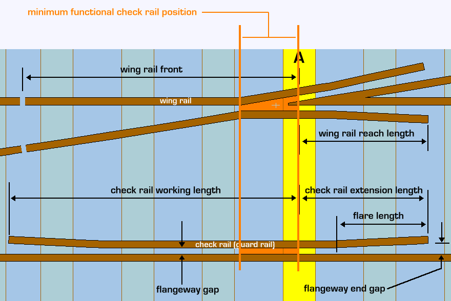
I am planning to extend the K-crossing check rails towards the common crossing, to make interior sort of Vs with machined ends so that the blunt tip is inside the envelope of where an actual "interior V" with 1mm flange ways would be. My representation in the plan is a bit clunky, but hopefully communicates the idea.
I don't think I will need the stumpy residual flared ends of the lower diamond check rails between the turn out crossing rails but I have represented where they might be. I am planning to make use of British Finescale templates at the corners of the formation so they are all Number 7 crossings.
Comments on my folly are welcome. Thanks, Tom
Attachments
message ref: 7611
 Search

