Templot Club forums powered for Martin Wynne by XenForo :

TEMPLOT 3D PLUG TRACK - To get up to speed with this experimental project click here.   To watch an introductory video click here.   See the User Guide at Bexhill West.

  • The Plug Track functions are experimental and still being developed. Some of the earlier pages of this topic are now out-of-date.

    For an updated overview of this project see this topic.   For some practical modelling aspects of using Plug Track see Building 3D Track.

    The assumption is that you have your own machines on which to experiment, or helpful friends with machines. Please do not send Templot files to commercial laser cutting or 3D printing firms while this project is still experimental, because the results are unpredictable and possibly wasteful.

    Some pages of this and other topics include contributions from members who are creating and posting their own CAD designs for 3D printing and laser-cutting. Do not confuse them with Templot's own exported CAD files. All files derived from Templot are © Martin Wynne.
  • The Plug Track functions are experimental and still being developed.

    For an updated overview of this project see this topic.   For some practical modelling aspects of using Plug Track see Building 3D Track.

    The assumption is that you have your own machines on which to experiment, or helpful friends with machines. Please do not send Templot files to commercial laser cutting or 3D printing firms while this project is still experimental, because the results are unpredictable and possibly wasteful.

    Some pages of this and other topics include contributions from members who are creating and posting their own CAD designs for 3D printing and laser-cutting. Do not confuse them with Templot's own exported CAD files. All files derived from Templot are © Martin Wynne.

Using the Templot rail filing jigs

Quick reply >

Martin Wynne

Admin
Location
West of the Severn UK
Info
.
Enjoy using Templot?
Thanks.

Please do not send requests for help direct to me via email.

Post your questions on the forum where everyone can see them and add
helpful replies.
index.php


These rail-filing jigs were introduced in Templot 241b and can be 3D-printed for any crossing angle 1: 0.5 to 1:20 and for any switch size A to F.

The jigs are intended to be FDM printed using toughened PLA Plus filament to resist filing -- the same material as is used for the timbering bases. The cost of filament is under £1 per jig for the vee rails and under £2 per jig for the switch blades.

The overall size for most angles is 90mm x 50mm. The thickness can be set as required -- the default is 19mm.

The large opening in the middle allows it to be clamped on the corner of a table, if holding it in a bench vice isn't convenient.

Using all-threads with double wing nuts makes it easy to hand tighten without needing any other tools ( screwdriver, spanner, socket) on the head, but obviously any ordinary M6 (6mm) bolts will do, such as widely available roofing bolts.

The square holes are slightly undersize -- firmly push the bolt through the hole to create a close fitting bolt which will help to align the two halves.


index.php


p.s. that's grey FDM filament, not a resin print.

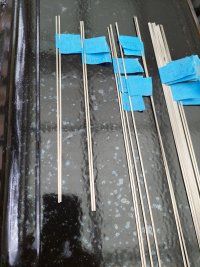
The jigs are used by clamping the rails in the slots with the M6 bolts, with enough rail protruding on the filing surface to be filed off at the required angle. The assembled jig can be held in a bench vice, or G-clamped onto the corner of a table through the large opening in each one.

Before finally tightening the bolts, check that both halves of the jig are flush with each other along the filing surface.

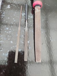
Use a good quality 2nd-cut engineer's flat file, and lightly finish with a flat 400-grit sanding block. The file will barely harm the jig, but the sanding block can do, so it is used lightly just to remove the filing scratches from the metal, so that the rails can fit snugly together.

Unless it is a very expensive file, it is unlikely to be dead straight. Looking along it you will likely detect that it is fractionally curved. If so, use the convex side for best results on the jig.

While filing, brush away the filings between every few strokes. The file itself won't harm the jig, but rubbing metal filings into the surface will do. Fully disassemble the jig after each use, so that you can remove any filings or other debris from the slots. The jigs will last for a great many filed rails, but being plastic, they need to be treated with care -- otherwise you will soon be printing a replacement. :(


1. The crossing jig makes both point and splice vee rails by turning the rail the other way up. They are opposites for the opposite hands of a V-crossing. The point rail forming the nose of the vee goes on the main side (MS) of the crossing.

After filing, the point rail should be blunted back to a width of 0.25mm (10 thou) at the tip by trimming with sharp snips and sanding smooth. When correct it should slide into the "A" chair and stop with the nose just on the far edge of the chair. Check it is the right way up and hand for the "A" chair, LH and RH chairs are handed.

The splice rail is not blunted back, but it's a good idea to remove the tiny feather of metal which remains from the rail web at the tip. The rail should slide up to the point rail and fit snugly against it.

The rails will only fit snugly if they have been filed using filing jigs exactly matching the crossing angle -- hence including the jigs in Templot.

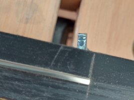
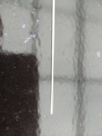
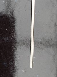
This below is how the filed vee point rail fits in the plug track "A" chair. This is for a Left-hand V-crossing looking towards the vee nose and showing the main-side (MS) wing rail:


index.php


More information about the above is at:

https://85a.uk/templot/club/index.php?threads/experimental-plug-track-continued.673/post-8369


2. The switch blade back jig should be used first to prepare the backs of the blades. Again turning the other way up for the opposite side of the switch. The final tip of the blade will be at exactly 20mm from the end of the jig, so you probably want to start with the rail at about 19mm before filing. After filing, mark it at 20mm with a permanent marker.


3. The switch blade front jigs are separate jigs for left and right switch blades. This "left and right" refers to the sides of the switch looking from the toe, NOT the hand of the turnout.

Insert the rail with the back already filed so that the mark is again exactly 20mm from the end. The jig is designed to accept the angle filed on the back at that rail position. That's the theory. In practice because of FDM printing variations you might find tweaking it a little forward or back fits best. Again clamp very lightly at this end.

The process of filing the back of the blade may have caused the rail to curve slightly where it is filed. If so, gently straighten it in your fingers before doing the front of the blade.

The jig allows you to file across the head of the rail at 20 degrees, producing a sharp tip at the toe and leaving most of the rail foot intact. Make sure you have the correct rail the correct way up. The filed end will be sharp -- keep some Elastoplast handy. :)

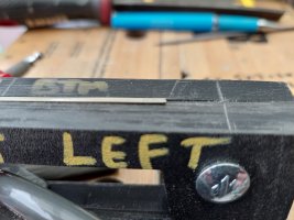
For all the switch jigs, front and back, I suggest applying a strip of sticky tape down the face of the jig at the working end of the jig:


index.php


This will allow the bolt at that end to be tightened without pushing the rail at that end up out of the groove, causing over-filing.

This is electrical insulating tape, which is 5 thou thick. So increasing the groove depth at that end by 10 thou. This won't significantly affect the accuracy of the jig, but will ensure that the rail can lie flat in the groove. The bolt at the other end can be fully tightened to clamp the rail in the slots and ensure that the rail is prevented from moving.

This applies only to the switch jigs and does not apply to the crossing jigs.

The above tape is not necessary in Templot program update 244a and later. The extra spacer is included in the jig.


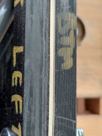
If you mark along the rail with a marker pen before starting, you can see where you have filed. For code75 bullhead rail in 4mm/ft scale, the filing should run out at a filed length (planing length) of 29.3mm from the tip for B blades, i.e. at 49.3mm from the end of the jig. Mark this position on the blade.

Here is a handy chart of blade planing lengths and deflection angles for different switches:

planing_angles_chart.png

More prototype info about switch blades is at:

https://85a.uk/templot/companion/real_track.php#planing_types


4. The final task is to make a very slight bend in the rail at that position, towards the centre of the track, until the filed top front running edge aligns in a straight line with the remainder of the rail. This is best seen by eyeing along the rail, but don't poke yourself in the eye with the sharp tip.

For the curved switch blade, do this first before curving the rail to match the template.

There are likely to be some burrs on the filed edges which can be fettled with fine abrasive paper. Do this on the bottom of the blades before assembly, and after assembly for the running top of the blade so that it blends in against the stock rail.

Martin.
 
_______________
message ref: 7727
Hi Martin,

On the subject of your filing jigs
I have been having a few issues getting the key last 1.6 mm layers to work satisfactory on the back switch blade jigs. I don't seem to be able to get the left and right Jig to hold the rail the same I can got one quite good but not the other with the same printer settings.
Anyway as such I have reverted to only making the jigs 3.2 mm thick to save both time and filament. until I figure it all out.

It then stuck me would it be possible to make the back filing jigs and maybe even the Vee crossing jigs ( less critical) as there a lot smaller. in four parts not two. The idea is the critical working side can be printed at a much finer Cura settings, and then the 6 mm or so backing section could use a more course setting.
Its a sort of cheat way of getting around the Cura single layer settings issue, we talked about at the zoom meeting.

Think of it more like a sandwich where the metaphorical meat, is the fine scale detailed parts of the jig and the outer sections are the two layers of bread.
I know I could simulate this right now, but I feel to do it justice a pair of alignment peg and mating holes would be required, these in conjunction with the two square bolts should ensure arcuate alignment every time.
I would welcome your thoughts?

I know that's more work, however I fear unless I have been very unluckily a very good level of Cura Know-how will be required to get these switch blade jigs to work easily every time. Thinner working parts don't help that directly, but they do save a lot of printer time if you don't quite have the setting dialed in correctly.
cheers
Phil
 
_______________
message ref: 8374
Hi Martin,

On the subject of your filing jigs
I have been having a few issues getting the key last 1.6 mm layers to work satisfactory on the back switch blade jigs. I don't seem to be able to get the left and right Jig to hold the rail the same I can got one quite good but not the other with the same printer settings.
Anyway as such I have reverted to only making the jigs 3.2 mm thick to save both time and filament. until I figure it all out.

It then stuck me would it be possible to make the back filing jigs and maybe even the Vee crossing jigs ( less critical) as there a lot smaller. in four parts not two. The idea is the critical working side can be printed at a much finer Cura settings, and then the 6 mm or so backing section could use a more course setting.
Its a sort of cheat way of getting around the Cura single layer settings issue, we talked about at the zoom meeting.

Think of it more like a sandwich where the metaphorical meat, is the fine scale detailed parts of the jig and the outer sections are the two layers of bread.
I know I could simulate this right now, but I feel to do it justice a pair of alignment peg and mating holes would be required, these in conjunction with the two square bolts should ensure arcuate alignment every time.
I would welcome your thoughts?

I know that's more work, however I fear unless I have been very unluckily a very good level of Cura Know-how will be required to get these switch blade jigs to work easily every time. Thinner working parts don't help that directly, but they do save a lot of printer time if you don't quite have the setting dialed in correctly.
cheers
Phil
@Phil G

Hi Phil,

(I moved your post here.)

If you are finding that the rail slots are a tighter fit on one half than the other, I suggest increasing the rail width setting a fraction. Over the length of the jig, a slightly looser fit isn't going to make a significant difference to the filed angle.

p.s. the layer height should be 0.16mm, not 1.6mm!

Unavoidably there will be a Z-seam somewhere on the side of the slot. You can change its position in Cura, but ideally you need to change it between the north and south parts, which requires printing them separately. So it's generally too much faff -- if the seam is preventing the rail fitting, just carve it away with a craft knife.

We are limited in what we can do by the resolution of FDM printers. I can guarantee that if I added printed alignment pegs and slots, the filing faces would not line up perfectly flush. Best results are obtained by aligning the faces by feel when tightening the bolts, and tapping them with a soft-head mallet (or a wooden spoon) while the bolts are not quite fully tight.

As far as I know the only slicer which allows change of profile settings at different levels is Simplify3D:

https://www.simplify3d.com

I have a copy here obtained a few years ago, but it's ages since I last used it. Generally it's very good for engineering components, less so for toby jugs. But it's expensive when compared with other FDM slicers such as Cura which are free. So I tend to use and post about Cura because that's what most folks are using.

As I've mentioned before, my intention is to provide a utility function which will merge together two GCODE files from Cura created with different profiles, so that you can print the bottom section at a faster lower quality, and change automatically to a finer quality for the upper section. This will be very useful for the timbering bricks -- the rough part gets hidden in the ballast. 5 minutes extra in Templot might save a couple of hours printing time.

But it's not working properly yet and I can only do so much at a time -- I feel I'm being pushed to go faster. Folks just have to accept that plug track isn't finished yet, and won't be anytime soon. Using it now means accepting that some things are less than optimal for the present.

In any event I'm not sure it would be helpful for the filing jigs, there would almost certainly be a tiny ridge or step in the filing face where the profile changes.

I know the time taken to print FDM stuff bothers you, but I don't find it a problem. It's more than compensated for by the fact that FDM printers run for hours on end without needing the slightest attention. Which means you can get on with other work without giving the printer any thought. Invariably the printer finishes before I am ready for it. :)

Martin.
 
_______________
message ref: 8376
I know the time taken to print FDM stuff bothers you,
Hi Martin,
its not the time to print so much, as the time to print only to find a print failure. as an example a pair of full depth D size back switches take 19 hours to print.
Thanks for the help on the z seam looking at them that's could be the most likely the cause.

Please be aware it was not my intension to increase your work load, or force you to do anything you did not want to do. It was just a suggestion based on 48 hours of frustration of print fails.
I would be very keen to know if other people are also having issues with making the switch blade filing jigs. (please note the Vee blade are not presenting an issue at all.)

I will persevere with my idea of a four layer sandwich build, just to see what happens, if as you suggest FDM is not going to make an arcuate register, then the only downside will be the not required detail on the outer pieces.( there effectively going to be nothing more than width adders to help filing accuracy)
cheers
Phil
 
_______________
message ref: 8389
its not the time to print so much, as the time to print only to find a print failure. as an example a pair of full depth D size back switches take 19 hours to print.
@Phil G

Hi Phil,

If you need to change the default settings, the trick is not to start with D blades!

Do all your trial and error on thin test A blade jigs, which are a lot shorter. When you have got a Cura profile which produces good results for those, you should be able to change to doing full-depth D blades knowing the results will be equally good. If they are not, there is a problem with your printer, rather than the process.

But where are you getting 19 hours from? I've just tried slicing a pair of D blade backs, and using my usual profile for the jigs the time is half of that. 9 hours 48 minutes:

back_d_blade_cura.png


That's for 9.6mm thick each part, total jig 19.2mm. Showing as 108gm of filament, so under £2 material cost for one of the largest jigs. I will post the Cura profile I'm currently using shortly, you should get a similar result.

cheers,

Martin.
 
_______________
message ref: 8390
@Phil G

p.s.Phil,

Here is my current Cura profile for the filing jigs.

n.b. Cura will accept this only if you have set a custom printer as the active printer.

It should show around 9 hours for the D blade backs.

Martin.
 

Attachments

  • Templot_filing_jigs_13oct2023_plaplus_cura5p4p0.curaprofile
    1.2 KB · Views: 51
_______________
message ref: 8392
Martin

Thanks for all the work you are doing and I am sorry if you feel we all are pushing you in several directions, its just the excitement of getting going with the system

Just a short story about how 3D printing can change how you work. 15+ years ago my golfing partner was a jeweller. He designed and mad bespoke jewellery. He designed rings on cad, got them printed in wax, fettled them and sent the wax masters off for casting in gold. He got a bit fed up with the lead times from the 3D printers so took a leap of faith and brought his own printer. He started off printing off his own designs, which took more than 12 hours to print. (he just set it up and either went to work or bed)

His friends found out he had a printer and got him to print their work ( there was plenty of space on the print bed for other items) In short instead of the machine paying for itself in a few years, it paid for itself in months

I am not saying we all start printing for others, but simply we adjust how we model and as you say learn how to set up the print run and get on with something else

On a personal note what does worry me is in the setting up of the settings, still I think I should just work steps learning each process one at a time.

Looking at what is being achieved to date is quite exciting
 
_______________
message ref: 8393
On a personal note what does worry me is in the setting up of the settings, still I think I should just work steps learning each process one at a time.
@Hayfield

Hi John,

Don't worry about the settings. I shall be posting everything you need, which you should be able just to copy and use straight off without any problems -- especially if you are using the same printer and materials as me.

It's inevitable at this stage that folks post questions and complications while getting started, especially if they have been doing things differently on their printers or track-building up until now. It makes it seem that there are lots of problems when mostly there are none. See for example the issues created yesterday by using pre-soldered vees because that's how we have always been doing them -- but they don't work on plug track. I assumed everyone had noticed that they are similarly not used in the 3D-printed Finetrax kits but perhaps I should have made it clearer from the start. @James Walters

cheers,

Martin.
 
_______________
message ref: 8394
Hi Martin,
Just a few observations on the filing Jigs A to E which I have to say once you get used to them, there great. the shots below are from a jig that's done 10 E blades so the ware and tare is not that bad.
As you can see for the first photo I have made a start on the Heaton Norris requirement's.

You are quite right the tape on A and B front jigs does work, however I also found it collects swarf quite easily, so as a preference I prefer not to use it and just lightly nip the wing nut in the filing side..
From C up to the E there is also most no chance of the front filing jig holding the filing area down in the jig, given it gets worst as the switch size increases.
I have put this down to a shallow gripping area as the switch length increase, also there is a natural bend that occurs after the back has been filed. Which I think is the rail stress reliving.
On The C size I found the answer is twofold,
1, don't start with the rail to be filed in the final position set it back about 20 mm and basically rough out the top rail section first, this is not only easier to grip but also causes some equalisation of the stress, noting the rail will still need some straighten once the front is partly filed.
2, make sure you apply enough downward pressure to ensure the rail remains in the jig groove, and then push carefully towards the clamed end, using the bottom part of the rail as a guide.
on the D and E its basically the same but I also use a 1" G clamp to act as a mid clamping point.
a few pics of the E rail fount being filed.
I also use the three files show in the last picture, a 2nd cut ward file, and then a no0 swiss file, and finally a no2 swiss file.
cheers
Phil
 

Attachments

  • 20240105_155040.jpg
    20240105_155040.jpg
    2.6 MB · Views: 67
  • 20240105_122514.jpg
    20240105_122514.jpg
    3.9 MB · Views: 69
  • 20240105_125348.jpg
    20240105_125348.jpg
    1.7 MB · Views: 63
  • 20240105_125817.jpg
    20240105_125817.jpg
    1.2 MB · Views: 52
  • 20240105_131116.jpg
    20240105_131116.jpg
    2.2 MB · Views: 51
  • 20240105_131128.jpg
    20240105_131128.jpg
    2.1 MB · Views: 58
  • 20240105_131926.jpg
    20240105_131926.jpg
    2.6 MB · Views: 68
_______________
message ref: 9876
Back
Top