Templot Club forums powered for Martin Wynne by XenForo :

TEMPLOT 3D PLUG TRACK - To get up to speed with this experimental project click here.   To watch an introductory video click here.   See the User Guide at Bexhill West.

     Templot5 - To join this open-source project on GitHub click here.  For the latest on-going developments click here.

  • The Plug Track functions are experimental and still being developed. Some of the earlier pages of this topic are now out-of-date.

    For an updated overview of this project see this topic.   For some practical modelling aspects of using Plug Track see Building 3D Track.

    The assumption is that you have your own machines on which to experiment, or helpful friends with machines. Please do not send Templot files to commercial laser cutting or 3D printing firms while this project is still experimental, because the results are unpredictable and possibly wasteful.

    Some pages of this and other topics include contributions from members who are creating and posting their own CAD designs for 3D printing and laser-cutting. Do not confuse them with Templot's own exported CAD files. All files derived from Templot are © Martin Wynne.
  • The Plug Track functions are experimental and still being developed.

    For an updated overview of this project see this topic.   For some practical modelling aspects of using Plug Track see Building 3D Track.

    The assumption is that you have your own machines on which to experiment, or helpful friends with machines. Please do not send Templot files to commercial laser cutting or 3D printing firms while this project is still experimental, because the results are unpredictable and possibly wasteful.

    Some pages of this and other topics include contributions from members who are creating and posting their own CAD designs for 3D printing and laser-cutting. Do not confuse them with Templot's own exported CAD files. All files derived from Templot are © Martin Wynne.

3D printers - messin' with resin

Quick reply >
Many thanks for the comments. All in all a pleasing result for a first effort.

The pong wasn't quite as bad as I feared, although it is very pervasive and still strong in that room this morning. I had the window wide open and a big fan blowing out through it as an extractor. A more engineered version of an extractor fan is on the cards.

The unsung hero of the evening, and not even mentioned in the instructions, is the plastic hook thingy to hold the build plate at 45 degrees while it drips the worst off. The print took 19 minutes and I left it dripping afterwards for about 20 minutes. All that time with the lid on and the air filter doing its stuff. I don't know how much effect the filter had, but the pong in the room got significantly worse later while cleaning up.

I then transferred the build plate quickly to the washer. With the holder at its lowest setting it required 1.5 litres of IPA (half the full capacity of the tub) to cover the plate. After finally realising that the washer won't start without the lid on (!) I gave it 5 minutes machine washing. Then a further 0.5 litres of IPA in an ice cream tub for brush washing (with a Lidl no.12 flat watercolour brush, other brushes are available). With intricate detailed parts I imagine thorough cleaning with a fine brush is important to reveal the full detail.

After which the print peeled away from the build plate quite easily with minimal persuasion from the scraper. Finally I put it in the basket for another 5 minutes machine washing, although whether that made any difference I don't know. I ideally you need a second tub with clean IPA for a final wash -- I will look at getting one.

Then a blast with the air gun which I use for removing dust when scanning negatives (other hairdryers are available) to dry it off. Finally back into the machine for curing. The turntable is a fiddly thing to engage the two studs. I supported the print on a small glass jar to put it more central within the UV lighting. I gave it 2 minutes as suggested, but it was still quite soft and flexible when removed. It has since hardened noticeably on the window cill this morning, so I may give it longer next time.

I didn't want to put the used resin back in with the new, so I found a black polypropylene container for it until next time. I couldn't find any information about a suitable container for it, but so far there has been no reaction with the polypropylene. I used a plastic funnel to support the disposable filter supplied -- bad move as it made one more thing to clean up afterwards. In future I shall use the disposable filter unaided (10 supplied).

The messiest job is cleaning up the resin tank. I wiped it out as clean as possible with kitchen roll, and then dunked it in the ice cream tub for brush washing. Obviously any smears of resin left on the film will harden and interfere with future prints, so it's important to get it completely clean. In case there is any resin left on it, I have stored it in the dark until next time (actually in the box the toolkit came in). There is a pouring lip in one corner of the tank, but clearly it was designed by a left-handed person because for me it seems to be in the wrong corner.

I've learned for next time that you need lots of clear bench space for putting things down, several old biscuit-tin lids ready to put them on, a big roll of kitchen towels, and a big tie-handle plastic bag to put the used ones in. The whole process seems a bit environmentally suspect, but we are not planning to make chairs on an industrial scale.

All in all a lot to learn, and it's a bit unpleasant to work with. Unlike using the Bibo FDM printer, which is a laid-back breeze in comparison, with a pleasant smell reminding me of childhood jam-making and blackberrying on summer afternoons long ago. The Elegoo reminds me only of my A-level Chemistry exam. :)

cheers,

Martin.
 
_______________
message ref: 831
Martin,

If you are going to use the printer fairly regularly, then you can leave the resin in the tank on the machine and cover it over to stop anything dropping into it. It saves all the hassle of decanting the resin somewhere and cleaning out the tank. You just need to give the resin a bit of a stir before use using a plastic utensil - I use a bit of 3mm styrene sheet although I've got a plastic scraper somewhere which came with my original printer but I can't find it. :) I now only empty the resin tank when I have to clean the FEP, change the FEP or change the resin.

Jim.
 
_______________
message ref: 833
Hi Martin,
My printer and wash/cure unit have been delivered and tomorrow I shall make use of all the good advice posted here to set it up ready to try it out.
I only have one track file at the moment which I think somebody posted some time ago. It's half a dozen sleepers with chairs.
I would be very grateful if you or any one else could let me have some stl files of chairs/sleepers etc to try out and experiment with print settings.
I'm modelling in 4-SF.
I can make a dropbox upload link available if necessary. (You don't need dropbox to use it.)
Many thanks.

Charles
 
_______________
message ref: 837
I've been thinking a bit more about the missing chairs.

As the build plate lifts, some fresh resin must get sucked in under it. Anything very delicate near the edge may get dislodged by the incoming tide. Such as the first bottom layer of the chair plug, which is only 2 thou thick. This would suggest there is an area about 20mm wide all around the build area which can't be used for fine detail.

The solution would be for the underside of the chair plug not to be flat, but deeper in the centre, so that the area increases gradually as new layers are added. And maybe change the lift speed.

I can see there is going to be a lot of tweaking and trial and error needed to reach a final working design.

Martin.
 
_______________
message ref: 839
I found the missing bits of half-printed chair lurking in the resin, partly stuck to the FEP film, but easily removed. This surely affects the idea of leaving the resin in the tank unfiltered for next time? They would clearly impede the first layer of the next print. So if doing that, it would be important to check that the previous print was fully formed with nothing missing.

Martin,

You have to check out your prints to make sure everything is there if you leave the resin in the tank. You can double check that the FEP is clean by gently scraping a plastic scraper along the FEP to check for stuck on bits when stirring the resin to mix it up in the tank. If you can feel anything, then you can empty the resin out through a filter to catch any loose bits then clean the FEP.

There's also a facility on my Phrozen Sonic Mini to clean the VAT. This illuminates the LED array for a period with no build plate involved, and it forms a thin sheet across the whole print area which includes any bits left on the FEP. You can then remove this thin sheet along with all the left over bits. I find it a bit fiddly to get under the edge of this film to lift it out of the tank with the resin still in but I'm getting there, using a bit of thick styrene as a tool. I'm assuming that the film should be removed leaving the resin in the tank otherwise, if you have to pour the resin out before removing the film, why bother using the facility in the first place. :) It's a new thing to me and I'm still finding out about it.

Jim.
 
_______________
message ref: 840
Last edited:
I've installed an extractor fan (formerly from some long-gone PC). Just need to make the enclosure.

DSCN5027.JPG


DSCN5024.JPG
 
_______________
message ref: 854
Hi Martin,
Yes, 4 chairs at each end of the strip were missing.
Direct export from Templot would be fantastic. I'll keep everthing crossed . :)
I'm going to have a proper play tomorrow.
I've also got to get my head around the slicer settings.
Is it possible you could tell me the settings you actually used?
A photo of the relevant page in Chitubox would be fine.

Charles
 
_______________
message ref: 861
Hi Martin,
Yes, 4 chairs at each end of the strip were missing.
Direct export from Templot would be fantastic. I'll keep everything crossed . :)
I'm going to have a proper play tomorrow.
I've also got to get my head around the slicer settings.
Is it possible you could tell me the settings you actually used?
A photo of the relevant page in Chitubox would be fine.

Charles

Hi Charles,

The missing end chairs are so repeatable and predictable that it looks to be something in the machine or software rather than just happenstance on the day. Something to investigate or find a work around for. I have already changed the bottom of the plug to be thicker in the centre -- there will be a clearance in the sockets anyway.

Did you empty and filter your resin tank? If not bear in mind that the missing chair bits will be still in the resin, to cause problems with the next print.

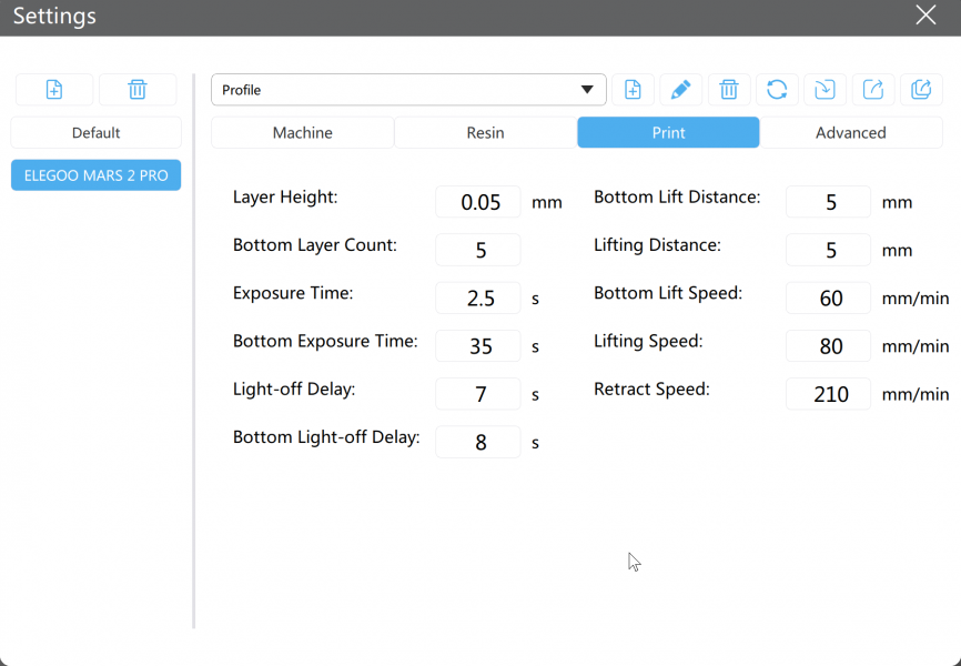
In the end I didn't change any Chitubox settings, I used the preset defaults for the Mars 2 Pro:

chitu_elegoo1.png


chitu_elegoo2.png


The settings are under the Print tab:

chitu_elegoo3.png


and can be changed as required.

This is utter simplicity compared with the dozens of settings and options for filament-printing. Ideally we would set finer layers for the chairs only, and not the whole thing, to save time. But that option doesn't seem to be available.

But given the results with the default settings above, there doesn't seem much reason to change them. Obviously layer height and exposure time are inter-dependent, so it would be easy to mess it up. :)

cheers,

Martin.
 
_______________
message ref: 864
_______________
message ref: 865
Hi Martin,
Interesting, your default settings are not quite the same as mine.
This is the latest version of Chitubox - 1.8.1
View attachment 662

Hi Charles,

That's interesting. Did that version of Chitubox come on your USB stick or have you upgraded since? I saw that there was an upgrade available, but decided to leave it until I had got going with the software actually supplied with the machine. The settings in there correspond to those in the printed manual (which is also the same on the latest download of the manual).

However, there is a spreadsheet available online which corresponds to your later settings, and has different settings for different resins and colours:

https://www.elegoo.com/blogs/3d-printing/elegoo-printers-resin-setting-sheet


mars2p_rec_settings.png


The significant change is the longer 2.5 second exposure time, and slower speeds. The only way to find out which works best is to try it and see on the same print. The longer exposure may make a stronger print with no effect on detail, or it may cause each layer to flash into the next, losing some of the finer detail. I don't know what difference the speed of movement makes to the print quality. But the overall printing time will be increased on the later settings.

p.s. did you notice on the box the resin came in, that "red" and "maroon" seem to have got swapped over? And also that "grey" is spelled like that in the UK way? (And above). On everything else in the IT world it is spelled "gray". Hmm.

cheers,

Martin.
 
_______________
message ref: 867
Loaded up your chair Chitubox project, scaled it ro S (119%) and saved it to suit my Phrozen Sonic Mini 4X and the Phrozen ABS-like Grey and had a print.

TemplotChairs-01.jpg


All chairs printed


TemplotChairs-02.jpg


A bit closer showing the layering at 0.05mm height. The print had a scoosh of Halford's Grey Primer to make it photograph better. I think I would try it at 0.03mm to see what the improvement might be. Anti-aliasing had been applied - setting "4" in Chitubox. But you don't actually notice the layering when viewed by eye.

TemplotChairs-03.jpg


And the chairs fit SSMRS Code 87 rail very well. :)

Have you got the original chair .STL without the plug and the single heavy support so that I could experiment with other methods of setting the chairs out for printing?

Jim.
 
_______________
message ref: 868
Have you got the original chair .STL without the plug and the single heavy support so that I could experiment with other methods of setting the chairs out for printing?

Hi Jim,

Sorry, no I haven't. I probably do have the DXF which I could edit. If I can find it -- I've generated 100s of DXFs in the last few days while working on Templot. I will have a look.

But here is the STL with the supports, which you could presumably edit in CAD?

I don't think scaling the CTB will work, will it? The layers were already sliced at 0.05mm, so by scaling you have increased them. I think you would do better to scale this STL, and then re-slice it.

mars_first_try.png


p.s. "scoosh" is now my word of the day. :)

cheers,

Martin.
 

Attachments

  • mars2p_s1chairs_first_try.stl
    4.3 MB · Views: 347
_______________
message ref: 869
I don't think scaling the CTB will work, will it? The layers were already sliced at 0.05mm, so by scaling you have increased them.

That seems to be the case. Original STL for slicing:

stl_org.png


CTB rescaled -- Chitubox is attempting to re-slice this:

ctb_rescaled.png


cheers,

Martin.
 
_______________
message ref: 871
Have you got the original chair .STL

Hi Jim,

Sorry, there isn't such a thing. I could generate one for you, but not just at the moment because I've got Templot in bits while I'm working on it.

I think we may be at cross-purposes. These chairs are generated by Templot on the fly, I'm not using any CAD program such as Fusion to create STL files.

If I switch the plug off, or switch the sleeper off, the chairs will be hollow. Probably the online fixer could make them solid.

cheers,

Martin.
 
_______________
message ref: 875
Hi Jim,

Here you go. Sleepers deleted from the DXF in TurboCAD. Saved as STL. Fixed solid in the online tool. 4mm scale (to fit Exactoscale rail):

chairs_only_for_jim.png


You will need to rescale the STL for S. I don't know how you are going to support them and keep the base dead flat for use?

cheers,

Martin.
 

Attachments

  • exacto_chairs_only_mm_fixed.stl
    2.2 MB · Views: 378
_______________
message ref: 878
I don't think scaling the CTB will work, will it? The layers were already sliced at 0.05mm, so by scaling you have increased them. I think you would do better to scale this STL, and then re-slice it.
Martin,

I'll have another go with the .STL file.

I had another look at importing your Chitubox project file and now that I look closely at it, I see the extreme layering on the image on Chitubox after scaling - I didn't look closely the first time. :) I think Chitubox has developed quite a bit over the years and I dug up some of my project files from two years ago when I was working with a very early number version - probably around V1.2 or V1.3. I could load them and re-scale them with no problems. So it looks as though the current project files are storing the sliced .stl including sliced support stl information whereas the early versions were just storing the stl files of the part with supports. When I rescaled these early files, Chitubox removed the supports (after a warning).

Jim.
 
_______________
message ref: 879
Jim,

I'd be happy to send you some of my STL files for 7mm chairs, as per the images earlier in this thread. The files are on the large side though.

Martin used WeTransfer which seem to work quite well.

The offer is there.

Richard.
 
_______________
message ref: 880
Hi Jim,

Just to explain, Richard's STL files are incredibly detailed CAD renderings of prototype chairs:

richard_chairs.png


With separate keys and even including the code letters on the screw heads. I'm going to have a go at printing them when I've got a bit more time.

My chairs are simple geometrical approximations which can be generated on the fly in Templot. There is no CAD program involved:

templot_chairs.png


Two different things.

I fear I shall have my work cut out trying to get this difference across to 3D printing users when/if I finally get a Templot update released. :(

cheers,

Martin.
 
_______________
message ref: 881
Hi Martin,
This is excellent news.
For some reason I've been holding back building the bulk of the the track on my magnum opus layout.
(I've just got a small terminus built at the moment using copper clad).
Now I know why :) .
Perfect, I can print the sleepers on my Prusa I3 Mk 3S and now the chairs on the Elegoo Mars.
I can't wait. :):)

Charles
 
_______________
message ref: 886
I printed the chairs stl last evening and printed them directly on to the plate and they all stuck using the standard settings for the Phrozen printer and the Phrozen resin.

TemplotChairs-04.jpg


Not the best of shots but I had to fiddle around to stop too much light reflecting off the plate and still get a reasonable image of the chairs.

They have come out quite well but are a bit of a handful when working with them during the washing and curing phase - three have disappeared already. :)

TemplotChairs-05.jpg


For the same reason, they have not had the aerosol spray treatment so they have that slightly off focus look of cured 3D resin. They also don't appear to have acquired a noticeable elephant's foot after printing on the plate.

TemplotChairs-06.jpg


...and just a check that they fit the S scale rail.

I think if I was going to print a large number of them, I would print them on the plate but add a sprue between them to keep everything together during the post-printing handling. If the sprue made contact with the chair base under the rail then you wouldn't need to be too fussy about cleaning up sprue pips when you break the chairs off.

Richard

I would be interested to experiment with one of your chair files to see what I can do. I'm up to my eyes with getting an N scale layout (actually FS160) ready for an exhibition in November and that's taking up most of my time at the moment. Optimism reigns down in the West Country. :):) So I don't want to get too involved in chair making - I've just been following Martin's adventures over the past year or so and thought I might have a try at printing some of his output, mainly to try out my new mono printer to see what it can do.

Jim.

Jim.
 
_______________
message ref: 887
_______________
message ref: 891
Hi Tom,

For me the big change was the realization that I could at last afford to buy a resin printer for the cost of a few Shapeways prints :D

Cheers,
Andy

PS Anyone want a mark one plywood and string (no kidding) FDM printer?
 
_______________
message ref: 893
I rediscovered the attached track panel(s). I think I was going to have Shapeways print them but my forgetory is such that I don't know if I ever did or not :giggle: The S1 chairs are quite good but IIRC they are designed for SMP rail which is a bit narrow.

The edge filleting on the chairs was done in TurboCad Pro which is a bit spendy but I'm tempted to buy the latest version because of the detail that the resin printer can produce.

The attached file is a DXF which you might be able to edit.

Andy

RATS! The file is too large. Where should I put it?

But here's a screenshot.

Screenshot (1).png
 
_______________
message ref: 894
Last edited:
Interesting reading all these threads on 3d printing chairs. I have been 3D printing printing for a number of years now and acquired my second printer a few months ago. The printer was a fraction of the price I paid for the first printer and can print down to 10 micron layer thickness. I model in EM and planning on building a Midland Railway layout. I have noticed that nobody makes some of the chairs that are required to make a prototypical point and they have to be made up from sliced up chairs. Exactoscale do a check rail chair but only for P4 with a .8mm flangway gap. In EM it should be 1mm so I decided to make a MR one. I haven’t printed it out yet but looking forward to seeing what the results will be like. I was planning on making some of the other chairs for various crossing angles but if anyone have already done these and would like to share their results in return for printing them I would be interested. Below is an example of some coach parts I have printed and my 3D MR check rail chair. These coach parts were printed straight onto the build plate and did not require supports under them contrary to what some modellers do.

MRCCR.JPG


Coach fittings 2.jpg


Thomas
 
_______________
message ref: 905
I've been mucking around with TurboCAD (Platinum unfortunately) and I was able to create this in less than an hour.
Hi Andy,

Very good -- so far. :)

Chair screws have a tapered square head. Below that is a pan flange, which is larger than the tapered oak ferrule which locates in the tapered hole in the casting:
chair_screw_400x742.png

The ferrule provides a precise location on the timber without needing a close tolerance hole in the casting. The ferrule stands proud of the casting to be effective. If frequent tightening cause the screw to contact the casting, the ferrule must be replaced. Different sizes of ferrule are available for maintenance purposes. Modern ferrules are no longer oak, but a tough plastic polymer.

This is Templot's generated geometrical version of that, I think the flange could be beefed up a bit.:

dxf_screw_head_860x646.png


cheers,

Martin.
 
_______________
message ref: 950
Thank you for that Martin.

I guessed the square heads were 1.125" so I was not too far off. I can easily taper them and fillet the corners too. Probably a waste of time for 1:76.2 but I'm drawing it actual size so it can be scaled.

My base plate might be a bit too thick. It's currently 5/8" but looking at some photos I think it should be a bit thinner.

How high are the tops of the screws relative to the timbers typically? (There's not too much bullhead track in North Idaho for me to measure :D)

This started off as a bit of an exercise to see how well TurboCAD produces fillets. So far I'm quite impressed. BTW, this is a solid model rather than a surface. I only applied the fillets after all the basic geometric shapes had been added together. It will be interesting to see if there are any holes in the STL. This version also has some 3D print tools but I have not investigated them yet.

The big snag is it is not cheap but it's nowhere near as expensive as the likes of Autocad. I decided it wasn't too bad if I amortized the cost over the number of years I'm likely to be able to use it. There are also annual subscription versions but I don't care for that approach. The 2020 download actually includes the code for all the versions including Platinum. You buy license keys that unlock the various features.

Like all things "you pays your money and you gets what you pays for" (in theory) and I concluded the resolution of the resin printer justified some decent CAD software. I suppose I could even defray some of the cost by producing highly detailed STL files and I'd at least be able to validate them by printing test pieces here.

Cheers,
Andy
 
_______________
message ref: 951
Hi Andy,

Answering for REA chairs (other chairs are available):

My base plate might be a bit too thick. It's currently 5/8" but looking at some photos I think it should be a bit thinner.

Chair base is 1/4" thick at edge.

Seat for rail is 1.3/4" thick.

How high are the tops of the screws relative to the timbers typically? (There's not too much bullhead track in North Idaho for me to measure :D)

Before tightening: about 3". After fully tightening: 2.3/4" min, say 2.7/8" in new track.


The standard REA chair drawings are available here:

http://www.lmssociety.org.uk/assets/pdfs/permanentWay1928.pdf

Unfortunately the scan quality is rather poor and some dimensions are difficult to read. Chair screws and ferrules are on page 1.
The ordinary S1 chair is on page 4.

Extracting some dimensions from more readable scans:

Screw head top. 1.1/16" sq.

Screw head at flange: 1.1/8" sq.

Screw head height above flange: 7/8" at side, 15/16" at corner.

Flange thickness: 3/8" at side of head.

Overall height of screw head and flange: 1.1/4"

Flange diameter 1.7/8"

Ferrule diameter at top (before compression): 1.35/64"


Boss on casting: overall height: 1.1/2"

Boss on casting: top diameter: 2"

Pictures of some chairs. Notice how prominent the screws can be. The screws are galvanised, the chair castings are raw, which is why the screws stand out in photos, especially when new:

bullhead_crossing_detail1.jpg


long_check3.jpg


pw_heap.png


p.s. I have copied the above into the Resources section, to keep the info easier to find, and allow it to be tagged.

cheers,

Martin.
 
_______________
message ref: 957
The big snag is it is not cheap but it's nowhere near as expensive as the likes of Autocad.

Hi Andy,

TurboCAD pricing is impossible to pin down, at least here in the UK. My version is TurboCAD Deluxe 2D/3D which cost me all of £9.99 as a special offer only a few years ago. I assumed others would be able to find it at a similar price. But searching comes up with £179.99 as the current price. The disparity between these two costs is difficult to fathom.

Autodesk's Fusion 360 is free for personal use. I believe it is popular with modellers for 3D printing. But it's online only, and involves jumping through several registration and login hoops to get there. I assumed that being from Autodesk it would support 3D DXFs from Templot -- it is after all their file format. But sadly no. :(

But I have now implemented a direct export in STL from Templot, so no-one now needs an expensive 3D CAD just to convert Templot's DXF output to STL for 3D printing.

cheers,

Martin.
 
_______________
message ref: 962
This afternoon's entertainment was to get the chair plugs into the 2D:

View attachment 716

I have put a 1/2" break across the plug corners for a clear fit in the sockets. For the bridge chairs I have increased the base overlap, so that the sockets do not get too close to the edge of the timber.

The plugs and screw centres aren't really needed in 2D, but the only way to check that the code is putting every one in the right place is to draw them on the screen.

One more tiny step on what is going to be a long journey.

Martin.
Hello Martin,
Is there a particular reason why you are using square/rectangular sockets for chair location? Would a round socket allowing them to rotate not enable one to adjust a chairs position indefinitely without restriction? Or am I missing something really obvious?
Trevor :)
 
_______________
message ref: 971
Back
Top