Templot Club forums powered for Martin Wynne by XenForo :

TEMPLOT 3D PLUG TRACK - To get up to speed with this experimental project click here.   To watch an introductory video click here.   See the User Guide at Bexhill West.

  • The Plug Track functions are experimental and still being developed. Some of the earlier pages of this topic are now out-of-date.

    For an updated overview of this project see this topic.   For some practical modelling aspects of using Plug Track see Building 3D Track.

    The assumption is that you have your own machines on which to experiment, or helpful friends with machines. Please do not send Templot files to commercial laser cutting or 3D printing firms while this project is still experimental, because the results are unpredictable and possibly wasteful.

    Some pages of this and other topics include contributions from members who are creating and posting their own CAD designs for 3D printing and laser-cutting. Do not confuse them with Templot's own exported CAD files. All files derived from Templot are © Martin Wynne.
  • The Plug Track functions are experimental and still being developed.

    For an updated overview of this project see this topic.   For some practical modelling aspects of using Plug Track see Building 3D Track.

    The assumption is that you have your own machines on which to experiment, or helpful friends with machines. Please do not send Templot files to commercial laser cutting or 3D printing firms while this project is still experimental, because the results are unpredictable and possibly wasteful.

    Some pages of this and other topics include contributions from members who are creating and posting their own CAD designs for 3D printing and laser-cutting. Do not confuse them with Templot's own exported CAD files. All files derived from Templot are © Martin Wynne.

3D printers - fun with FDM printers (Marlin-based)

Quick reply >
13. discard and ignore the supplied software and settings on the microSD card in the USB adaptor.
@Steve_Cornford @Hayfield

Hi Steve,

I have since discovered that the USB adaptor/card supplied with my printer is faulty and unusable.

If yours is the same, and you don't have another microSD card you can use, you can drive the printer directly from Cura over the supplied USB cable (if you can get your laptop close to the printer).

To do that, you may need to install the USB coms driver. I have uploaded a copy of that for you at:

https://85a.uk/odds/DRVSETUP64.exe

If you have a recent version of Windows it may be already installed.

cheers,

Martin.
 
_______________
message ref: 9633
@Steve_Cornford @Hayfield

Hi Steve,

So which printer to suggest? John has shown that it's possible to do good work in 180mm x 180mm, although there's no doubt that the extra 20mm each way is worth having. It is actually 210mm x 210mm bed size, but to use the full area would require a mod to the firmware settings.

cheers,

Martin.

For an old codger and technophobe its perfect

Watching two or three other videos on YouTube helped, as did the coaching from Martin.
The glass plate is much easier to level and has needed no further adjustments
Martins small sleeper test file was a godsend (have you got one for chairs using the Alkaid please)

And to a certain extent I have gone off piste with some test shots for 0-16.5 and 00e (12mm gauge) turnout bases. Which proves the ease of use in altering the settings in plug track

I have a few memory cards which I did find useful as prompts, whilst I got used to the method of making print files and printing process.

But to date I can recommend this printer, for a short bit I thought I may have jumped the gun and perhaps got the bigger printer, but seeing the extra skill needed to set it up I am relieved to have this one
 
_______________
message ref: 9635
@Steve_Cornford @Hayfield

How to break the Z-limit screw on the S1, put the clips in the wrong place, and get in a complete muddle with the levelling and different filaments:


I suggest stay with using PLA-Plus on these inexpensive printers. If you want to experiment with other polymers, and polymers filled with glitter and other materials, it might be better to get a more expensive printer in the first place.

Also the poor positioning of the filament break detector is very obvious. I didn't even bother to try it, or the blue bowden tube. (It's not fitted on the smaller printer.)

For the spring adjuster on the extruder, I left it as supplied turned fully clockwise. To feed the filament manually, turn the gear wheel with your fingers -- much easier then using the screen controls. Squeeze the lever to free the gears while inserting the filament.

cheers,

Martin.
 
_______________
message ref: 9637
.
index.php
 
_______________
message ref: 9638
Hi Martin,
Yes, I have a reel of ESun pla+ filament.
I also have been to my favourite shop in Hove, Namrick Nut & Bolt Store, to purchase 30mm M6 machine screws, washers and wing nuts, plus the all important 20mm M4 pan-head screw and some nuts as advised.
Unfortunately management has decreed that modelling be suspended whilst we prepare house for influx of visitors for Christmas!
I will have a go at installing Cura & setting up custom profile.
Regards Steve
 
_______________
message ref: 9695
Just recently got my Kingroon KP3S and this is the first attempt at a base.

This is with eSun PLA+ printed at 210 deg C.

Some stringing is clearly evident so I feel some tuning to the profile will be in order.

20231216_180729.jpg


Best regards,

Matt H
 
_______________
message ref: 9699
Just recently got my Kingroon KP3S and this is the first attempt at a base.

This is with eSun PLA+ printed at 210 deg C.

Some stringing is clearly evident so I feel some tuning to the profile will be in order.

View attachment 8129

Best regards,

Matt H
@Matt Harris

Hi Matt,

With eSun filament I prefer 185-190degC after the first layer. Also dropping the bed temperature to 45degC after the first layer. It all helps to avoid stringing, along with 6mm+60mm/sec aggressive retraction.

Also to get accurate socket wall thickness on plain sleepers you will likely need the modified flow equalization.

And concentric bottom pattern infill to avoid weak places in the timbering webs.

My Cura profile including the above attached below. In order to use it you will need to create a custom printer in Cura:

https://85a.uk/templot/club/index.php?threads/experimental-plug-track-continued.673/post-7361

p.s. If using the coated side of a glass bed, you may need to keep the bed at 60degC to ensure the part remains stuck to it.

cheers,

Martin.
 

Attachments

  • kingroon_190_6mmret_45bed.curaprofile
    2.2 KB · Views: 43
_______________
message ref: 9700
@Matt Harris

Hi Matt,

With eSun filament I prefer 185-190degC after the first layer. Also dropping the bed temperature to 45degC after the first layer. It all helps to avoid stringing, along with 6mm+60mm/sec aggressive retraction.

Also to get accurate socket wall thickness on plain sleepers you will likely need the modified flow equalization.

And concentric bottom pattern infill to avoid weak places in the timbering webs.

My Cura profile including the above attached below. In order to use it you will need to create a custom printer in Cura:

https://85a.uk/templot/club/index.php?threads/experimental-plug-track-continued.673/post-7361

p.s. If using the coated side of a glass bed, you may need to keep the bed at 60degC to ensure the part remains stuck to it.

cheers,

Martin.
Thanks Martin - I'm now running off a test print with this profile.

(I did change the bed temp to 55degC for subsequent layers to see how that goes)

Thanks

Matt H
 
_______________
message ref: 9702
.
As a trial for the filing jigs I have ordered some of this PLA-ST:

https://www.amazon.co.uk/gp/product/B08MVZKRD9

Which is claimed to be even tougher than PLA-Plus, and specifically intended for engineering applications. Slightly more expensive, so it will be interesting to see if there is any significant advantage over PLA-Plus (which works fine). There may actually be a disadvantage in that the claimed diameter tolerance is wider. As ever, the only way to find out is to get some.

Has anyone tried it?

There are many other polymers available of course, but I don't want to move away from PLA for user-friendly domestic printing.

Martin.
 
_______________
message ref: 9865
Hello,
What printer was actually used for printing track bases in the Bexhill West demo please?
I would like to know what size print dimensions where used as I assume bigger would be better for a large layout.
Thank you
 
_______________
message ref: 10015
Hi Trevor,

All the 3d printed chairs you will have seen on my YouTube channel have been printed with the Geetech Alkaid printer.
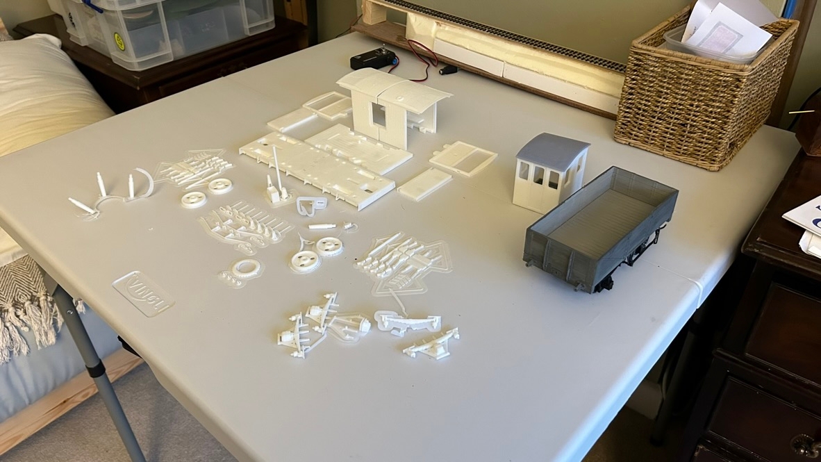
The 3mm scale chairs in the above image were printed on an Anycubic Mono 5s printer.
With regard to the chairs, bigger is not necessarily better, the little Alkaid printer will produce them far faster that one can lay them.
I use a Sunlu S9plus FDM printer for FDM track bases. I wouldn't recommend it, I have nothing but trouble with it. :(
For the laser cut track bases you will have seen, I use an OMTech 130w Co2 laser with a 1500 x 900mm bed. It's a useful machine but far too big and unnecessarily powerful for Plug Track use. The Creality Falcon2 22w laser which I recently reviewed is excellent, and I would say perfect for Plug Track use. I'll be reviewing the Atomstack 24w Pro laser next. I would expect that to be excellent as well, although it has a slightly smaller bed size.

As an aside, I think the ideal 3d FDM printer size-wise is likely to be the smallest that you need, rather than the biggest you can get. For the reason that a smaller bed size is easier to level and will be more consistent across the bed. I made the mistake of getting the Sunlu S9, because I went for a larger bed size than I really needed, and it is that which is at the root of many of the problems I have with it.

Martin and others are achieving excellent results with 'little' printers such as the Kingroon which I think will be my next purchase.
Remember, the trackbases can be split into small segments and joined accurately without being unwieldy.
I laser cut a 1200mm long triple track base for Bexhill West recently, and whilst it was nice to have it in one piece, it was verging on unmanageable to lay. I wont be doing that again. :)

I hope that helps.
 
_______________
message ref: 10016
Last edited:
As an aside, I think the ideal 3d FDM printer size-wise is likely to be the smallest that you need,
Just as a further comment to this, for FDM printers the bed size may ultimately come down to how you answer these two questions,
1,, are you planning to use the FDM filing jigs? ( especially the switch blade back filing jigs)
2, if so what is the largest size switch your going to use on your layout?

so for example in 4 mm scale the largest back filing Jig you could get on a 180 x 180 bed would be a "C" size switch, and only then if you printed it as two sperate half sides. Set at 45 degree angle.
For a 200 x 200 you can print a "D" size switch back filing jig, again printing as two separate half's and set at 45 degree rotation.
For something like an ender 3 with a bed size of 235 x 235 you can employ the same Idea and get up to an "E" size switch back filing jig.

Inversely if you wanted to print these jigs as a pair, I.e. both north and south half's attached.
Then the 235 x 235 bed could to print up to a "D" size switch pair.
the 200 x 200 could print up to a "C" size switch pair
and the 180 x 180 could print up to a "B" size switch pair.
cheers
Phil.
 
_______________
message ref: 10017
Hello,
The reason I was asking is because I have an old RepRap Mendal fdm printer from 2012 and I have never actually printed anything with it. The reason it has been under raps for so long was forgotten long ago.The build plate is 200mm X 200mm so I was thinking the section size of timber bases would be rather small. I am just on with finishing the commissioning of its build and getting software installed and updated. I will then be able to experiment. That was why I asked what filament printer was used for the FDM timber bases in the first Bexhill West demo about plug track. I suspect those printed on a RepRap Mendal will mean a lot more smaller sections being required.

Here is an image I what I want to print.

Layoutplan_20231216_224557.png
 
_______________
message ref: 10018
I laser cut a 1200mm long triple track base for Bexhill West recently,
Sounds like a case of chalk and cheese 1200mm vs 200mm. Or maybe the extremes of the working range? :)
@tervor that's a big layout to hand build track for. Doable for sure, but very time consuming, maybe more than one FDM printer would be a good option.
cheers
Phil,
 
_______________
message ref: 10022
Hello,
What printer was actually used for printing track bases in the Bexhill West demo please?
I would like to know what size print dimensions where used as I assume bigger would be better for a large layout.
Thank you
@Trevor @James Walters

Hi Trevor,

Do you mean these bases which James had on display at Scaleforum and used in his first video about plug track?


index.php


They were printed on my Elegoo Neptune 2S, which has a build area of 235mm x 235mm.

The 4th (pink) brick didn't get printed because I had to get them packed up in time to send to James:


index.php


Some of the connector clips are a bit oddly placed just to illustrate the flexibility of the settings.

cheers,

Martin.
 
_______________
message ref: 10026
Hello,
Thank you Martin. Everything I wanted to know is covered by your reply
The Reprap Mendal has a glass heated bed with a build volume of 200mm X 200mm.
But the clips holding it to the heated bed actually reduce the area available.
It will be ok for a bit of experimentation while I get the hang of producing bases.:):)
 
_______________
message ref: 10027
Hi Martin, Is it worth getting one of these 3D touch levelling sensor & probe for the KP3S Pro?
https://kingroon.com/products/3d-bltouch-leveling-sensor?variant=43024589160666
Seems to imply it will work on tempered glass heat bed plate.

Also in case anyone else is interested in one of these printers currently on offer @ £125.01

https://kingroon.com/products/official-kingroon-kp3s-pro-3d-printer?variant=44350481432794

Must get round to getting my one out of the box!
Steve
@Steve_Cornford

Hi Steve,

I don't see any use for the levelling sensor, or how it connects into the controls. There is no difficulty in levelling the printer manually, for anyone capable of building a model railway. Just listen for the click sound from the limit switch -- I think I wrote about it somewhere.

That offer version of the Kingroon printer doesn't have the linear guides on the Y-axis. Likely requiring adjustment to the rubber wheels -- much more tricky to get right than manual levelling!

Both those links are to the Kingroon warehouse, which I'm not minded to trust after the trouble not getting the printers. Altway in the UK seems a better bet (worked great for me):

https://altwaylab.co.uk/collections...ucts/official-kingroon-kp3s-pro-s1-3d-printer

cheers,

Martin.
 
_______________
message ref: 10147
.
URGENT - PRINTER RECALL

 
_______________
message ref: 10208
_______________
message ref: 10220
7 before dropping in z-screw, had to remove a very sticky transit label covering z-carriage hole.
Dropped z-screw in from top of z-axis.
Assisted z-screw thru z-carriage nut by rotating until it was fully home in the z-drive coupler.
Tightened the 2 grub screws.

I noticed the brass coloured plate fastened by 2 black screws on the top of the z-carriage was loose. Well the screws are loose.

Should I tighten those?
Steve
 
_______________
message ref: 10243
Last edited:
8 Removed string.
9 Checked belt tension. The ends of the X-belt that drives the extruder head were not connected to the extruder head. Each end has a clamp, and each slots into a bracket on the bottom of the extruder head. I inserted these then used the knourled nut on the end of the carriage to tighten until twanged.
Also tightened the Y-belt til twanged.
The question is how twangy? or do i mean pitch?

Steve
 
_______________
message ref: 10244
Extra Step, pre-empting advice in step 12.
The z-limit screw is mounted in a blind hole and is too long, so I removed the z-limit screw, added a nut, then shortened it by 3.5mm. cleaned up the end. Unscrewed the nut to ensure the thread was good, then added two nuts before replacing the z-limit screw without its spring. If using the spring instead of two lock-nuts the z-limit screw is a bit wobbly.
Steve
 
_______________
message ref: 10245
7 before dropping in z-screw, had to remove a very sticky transit label covering z-carriage hole.
Dropped z-screw in from top of z-axis.
Assisted z-screw thru z-carriage nut by rotating until it was fully home in the z-drive coupler.
Tightened the 2 grub screws.

I noticed the brass coloured plate fastened by 2 black screws on the top of the z-carriage was loose. Well the screws are loose.

Should I tighten those?
Steve
@Steve_Cornford

Hi Steve,

No. They are loose so that the carriage can align with the screw without requiring very close manufacturing tolerances. If you tighten them it is likely to cause backlash problems on the Z-axis. The Z carriage should be free to be lifted and dropped a fraction in your fingers without the screw turning. This allows gravity to provide the backlash correction, which works very reliably, provided you don't install the printer in a space capsule. Also, never enable the Z-hopping function in Cura.

I am just setting up my Kingroon Pro to remind myself of the settings -- I haven't used it for a couple of months.

cheers,

Martin.
 
_______________
message ref: 10246
Step 11
Even though I shortened the z-axis limit screw, I am having trouble getting it low enough for the extruder head to touch the paper on the right hand side.
The problem seems to be that the x-axis arm is not at right angles to the z-axis arm. ie the right hand end of the z-axis arm is canting upwards.

Surely the X-arm should be at right angles to the z-arm?

Steve
 
_______________
message ref: 10249
Surely the X-arm should be at right angles to the z-arm?
@Steve_Cornford

Hi Steve,

It should be, yes. But how far out is it? The important thing is that the bed is adjusted to be parallel to the arm. A slight error on the Z-angle relative to the bed won't be significant, at least for the timbering bricks.

You should be able to get the bed parallel to the X-arm by adjusting the yellow screws?

Also, check that the glass bed is clean on the underside, with nothing trapped under it. Check that it is the same thickness on each side. Ideally give it a wash in warm soapy water before first use. Mark it with permanent marker so that you can always use it the same way round. Are you using the coated side or the plain glass side? Have you removed the protective film on the glass bed (both sides?). Are the clips correctly fitted?

p.s. don't forget to check that the voltage selector is showing 230v before switching on. If you are using the USB cable from your PC, I recommend switching the power on before plugging the USB into the PC.

cheers,

Martin.
 
_______________
message ref: 10251
Hi Martin,
It is several degrees out.
In order to get the right hand side of the bed up to the extruder nozzle I will need to cut another couple of mm off the z-axis limit screw as it is bottomed in the hole,
Then I fear that the left hand yellow screws would need to be done right up against the springs so that there would be no give in the bed!
I have emailed Altwaylab using their contact form.

The glass bed only had protective film on one side (the coated side) which I have removed. I am using it upside down.
The clips are correctly fitted.


I note that I am not the only person to have had this problem, see:-

https://www.fabbaloo.com/news/hands-on-with-the-kingroon-kp3s-pro-s1-part-2

pity they didn't document the corrective steps!


Time for a spot of lunch before I go any further.
It is probalbly my fault as I scrambled my eggs this morning!
Steve
 
_______________
message ref: 10252
Back
Top