Templot Club forums powered for Martin Wynne by XenForo :

TEMPLOT 3D PLUG TRACK - To get up to speed with this experimental project click here.   To watch an introductory video click here.   See the User Guide at Bexhill West.

     Templot5 - To join this open-source project on GitHub click here.  For news of the latest on-going developments click here.  Templot5 is now included with Templot2 - download.

  • The Plug Track functions are experimental and still being developed. Some of the earlier pages of this topic are now out-of-date.

    For an updated overview of this project see this topic.   For some practical modelling aspects of using Plug Track see Building 3D Track.

    The assumption is that you have your own machines on which to experiment, or helpful friends with machines. Please do not send Templot files to commercial laser cutting or 3D printing firms while this project is still experimental, because the results are unpredictable and possibly wasteful.

    Some pages of this and other topics include contributions from members who are creating and posting their own CAD designs for 3D printing and laser-cutting. Do not confuse them with Templot's own exported CAD files. All files derived from Templot are © Martin Wynne.
  • The Plug Track functions are experimental and still being developed.

    For an updated overview of this project see this topic.   For some practical modelling aspects of using Plug Track see Building 3D Track.

    The assumption is that you have your own machines on which to experiment, or helpful friends with machines. Please do not send Templot files to commercial laser cutting or 3D printing firms while this project is still experimental, because the results are unpredictable and possibly wasteful.

    Some pages of this and other topics include contributions from members who are creating and posting their own CAD designs for 3D printing and laser-cutting. Do not confuse them with Templot's own exported CAD files. All files derived from Templot are © Martin Wynne.

3D track - fun with laser-cutters

Quick reply >

Phil G

Member
Location
New Zealand
PS you mentioned the possibility of a laser in part three or part four, do you know the size of the laser head your getting?
I am currently playing with a Fox alien Masuter pro CNC router, as the CNC control for the laser and a Lasertree 10W output diode,
it does work, and you can use it, but I have a strong feeling I would be so much better off with a 20W output laser.
The 10W either burns a bit too much on one pass, or need two passes for a cleaner cut. I am not sure repeatedly doing two cuts will hold the socket size accurately enough to be honest. I would be keen to understand what power laser your going to try?
cheers
Phil,
 
_______________
message ref: 9221
PS you mentioned the possibility of a laser in part three or part four, do you know the size of the laser head your getting?
I am currently playing with a Fox alien Masuter pro CNC router, as the CNC control for the laser and a Lasertree 10W output diode,
it does work, and you can use it, but I have a strong feeling I would be so much better off with a 20W output laser.
The 10W either burns a bit too much on one pass, or need two passes for a cleaner cut. I am not sure repeatedly doing two cuts will hold the socket size accurately enough to be honest. I would be keen to understand what power laser your going to try?
cheers
Phil,
Hi Phil,
I've been offered a 20w laser to review, which has been held-up due to them being out of stock in the country at the moment. They have also offered a 40w laser to review thereafter. Hopefully both will turn-up as it would be nice to do a comparison. That said until they do I'm not counting my chickens.
I spent yesterday cutting some timbering bases for Navigation Sidings, and used the opportunity to test a variety of approaches, including cutting in 1, 2 & 3 passes, adjusting the power and speed for each approach. The neatest examples were cut in two passes at a relative fast speed and a medium power. Socket sizes didn't seem to be noticeably affected by the repeat passes, and the chair fit was excellent.
That was with my 130w laser though, things may be different with a lower power diode laser (although I suspect not), hence I'm keen to put one through its paces.
A significant downside to laser cutting 3mm ply is that the sheets often curl and getting them to lay flat on the bed of the machine can be tricky. To help with this I'm planning to make a little jig this week to constrain the sheets.

@Martin Wynne
A useful development for laser cutting would be the ability to view the nibs and snibs on the trackpad, and if possible adjust them for each timber possibly via the shove timbers box. I'm guessing that might be too tricky, but I mention it as food for thought. :)
 
_______________
message ref: 9234
Hi James,
That will be interesting to watch, I very much look forward to this video. who are supplying you with the lasers?
I agree about the sheet warping, not so much of an issue once cut, but can be a pain if its too bad on the burn, as it certainly affects the focus.
One issue I have found which I did not anticipate with my Fox Alien Masuter pro, it has a max travel of 2000 mm/min on X and Y which for cutting is more than ok, but for engraving is very limiting. I only went with Masuter Pro at the time, because it was the only one offering an extension kit, going up to 400 x 800 mm. cutting area now I believe X tool are doing the same thing!!!! at much more cost though.
cheers
Phil,
 
_______________
message ref: 9236
Hi Phil,
The lasers are Creality Falcon 2 machines, which have a 400x400 (or thereabouts) cutting area. Lightburn software allows for longer material lengths to be passed-through the machine, although I don't know if the Creality frame allows for this. It'll be on the list to check.
 
_______________
message ref: 9239
Hi Phil,
The lasers are Creality Falcon 2 machines, which have a 400x400 (or thereabouts) cutting area. Lightburn software allows for longer material lengths to be passed-through the machine, although I don't know if the Creality frame allows for this. It'll be on the list to check.
Do Creality offer an extension kit? warping issue aside The biggest single advantage I see for the laser its much bigger bed size option.
I have been looking at honeycomb pins last night as a means to hold the sheet flat need to fire up the laser and make some.
cheers
Phil,
 
_______________
message ref: 9243
I have a Creality Falcon 2 22w laser. It cut the sleeper in the attached photo in 3mm ply - 1 pass. A close look will show the nibs where the cut sleeper remained attached to the ply sheet before removal. O-MF gauge.

sleeper.jpg
 
_______________
message ref: 9247
I have a Creality Falcon 2 22w laser. It cut the sleeper in the attached photo in 3mm ply - 1 pass. A close look will show the nibs where the cut sleeper remained attached to the ply sheet before removal. O-MF gauge.
Hi Davey
what cutting speed and power level are you using for this cut? also what is the laser kerf valve you are using. Lastly am I right in assuming your laser cut width is 0.2 mm at the top of the cut?
cheers
Phil
 
_______________
message ref: 9248
Hi Davey
what cutting speed and power level are you using for this cut? also what is the laser kerf valve you are using. Lastly am I right in assuming your laser cut width is 0.2 mm at the top of the cut?
cheers
Phil
Phil
I cut these sleepers at 450 mm/s @100% as the 3mm plywood I was using has some odd glue that has toughened it up! For normal plywood I would expect to go quicker and not quite so hot.

I did not use a kerf offset in LightBurn as an O-MF sleeper is by nature quite chunky and 0.02mm of kerf adjustment is not going to make much difference. Martin's clip in, solid chairs were exported with default settings and fitted well in the sockets.

Finally, I would expect the cut width in 3mm ply to be about 0.2mm as you suggested.

Regards

Davey
 
_______________
message ref: 9378
Hello James,
Another very good video but then again you seem to be able to turn them out when covering most subjects. How do you see the cost breakdown of making laser cutters ? As with many devices the selling price is often set at a level that the market will stand in the initial stages of production. When sales have reached a certain level and the development costs have been recouped prices often drop a bit. Is the laser head the main expense for a company selling these ?

Have you found the secret to getting realistic corner joins on laser cut brick walls ? Usually do-able if you have stones covering the corner but on brick to brick joins not too easy. Unless you have a plan.....? It will be interesting to see your methods on painting brick structures too.

Rob
 
_______________
message ref: 9626
Hello James,
Another very good video but then again you seem to be able to turn them out when covering most subjects. How do you see the cost breakdown of making laser cutters ? As with many devices the selling price is often set at a level that the market will stand in the initial stages of production. When sales have reached a certain level and the development costs have been recouped prices often drop a bit. Is the laser head the main expense for a company selling these ?

Have you found the secret to getting realistic corner joins on laser cut brick walls ? Usually do-able if you have stones covering the corner but on brick to brick joins not too easy. Unless you have a plan.....? It will be interesting to see your methods on painting brick structures too.

Rob
Hi Rob, very interesting post,
re the cost of lasers, well more accurately diode lasers, its true there has been a direct cost to performance relationship, partly because as the manufacture moved from a single diode laser device (typically 5.5w output power) to the next generation which is, at as I understand it really two 5.5W lasers working though a light prism to create a single combined powered 10~11W beam. In fact its not a dissimilar set up to a Co2 laser in so far as the laser beam is manipulated through reflectors to get the final beam in the location there after. The reason I mentioned this will become more clear latter.

The next iteration was to take the same idea and double it again IE 4 x 5.5 W giving you an output of 22W (the same as the Creality James reviewed) There are already 30 W ( 6 x 5.5) and 40W (8 x 5.5) on the market.

There are two downside to this idea of just stacking up a series of 5.5w diode lasers, these are, as the power goes up so does the beam width meaning the kerf gets bigger (not ideal for 4mm and below modelling) the other thing that is happening and its something I only just realised the hard way yesterday, is the weight of the laser is also going up quite noticeably.

This could well start to create an issues which is currently not that obvious, in that as the weight goes up, so does the inertial force being applied to the frame of the machine and its servo sizing, which ultimately will result in frame flex or over travel and over burn ( something I have been experiencing on my system with 4mm brick work in the perps direction) (that's short for perpendicular and credit should go to James for explaining this to me.)

Creality have also produced a 40W laser which interestingly can be switch back down to 20 W for what there calling precision work. If James does get to do a review of this 40W laser. I for one would be very keen to see if firstly there is much added weight on the 40W device and secondly if the extra inertial force is notable on the the finished product, the perps of 4mm bricks being what looks to be a good test case.

This is something the co2 laser avoids because the only thing the head is moving is the final reflector so the weight of the actual co2 lasers is not relevant in this case.

The net result of all of this is, for a diode laser there has to ultimately be a power to weight ratio in terms of laser accuracy, my gut feeling is its at about 22W. Whilst the there is no doubt more powerful machines will be developed for people wanting to burn through thicker wood than say 12 mm or the people wishing to cut though steel or stainless steel. That will be an much smaller target market. I strongly suspect the days of next generation power, driving the previous generation cost down are coming to an end. Maybe not quite yet but a settling of price point will eventually happen.

To your point about the corners of bricks, if designed correctly there should be no reason you cant create a tongue and grove corner joint effect with the bricks, a bit like the old Linka system if you remember that. That would mean quite a bit of cleaning the exposed brick edges and would mean the total thickness of your material would have to equal the width of a brick header.

As for painting James has already done a very good video on painting and then getting a good mortar representation for laser cut MDF brick work.
Like many things the more effort you put into creating natural random toning of the individual bricks the better the overall effect. Something printed brick paper does very well to be honest, where brick paper falls down is getting a true feeling of depth.
Cheers
Phil
 
_______________
message ref: 9628
If anyone wants to give Laser cutting a go then I have a 3 year old Omtech 032B 40W CO2 laser for spares or repairs as I have a newer model. It does work but, one of the LCD's is faulty. Many spares and upgrades are readily available. This is Free to anyone who is willing to collect from South Buckinghamshire.

1703866447230.png
 
_______________
message ref: 9823
Hello James,
Another very good video but then again you seem to be able to turn them out when covering most subjects. How do you see the cost breakdown of making laser cutters ? As with many devices the selling price is often set at a level that the market will stand in the initial stages of production. When sales have reached a certain level and the development costs have been recouped prices often drop a bit. Is the laser head the main expense for a company selling these ?

Have you found the secret to getting realistic corner joins on laser cut brick walls ? Usually do-able if you have stones covering the corner but on brick to brick joins not too easy. Unless you have a plan.....? It will be interesting to see your methods on painting brick structures too.

Rob
Hi Rob,
I'm sorry I've been head-down for the past few weeks, mostly with work and I'd missed your post previously.

I think the laser head is the most complex part of the machine, although I expect that the selling prices will remain mostly static in the future, but with quality improvements. A bit like mainstream 3d printers have tended to go over the past few years.
Of course there are much cheaper options for diode lasers. I was looking at one this morning on Aliexpress (I think), for $133 dollars. This is probably much like the affordable Geetech resin printer, in that I'd expect it to work very well, as after all the basic mechanism is just stepper motors. The downside to the very cheapest diode lasers (unlike the Geetech printer), is that the safety controls become the users responsibility, i.e. making a hood, rigging-up extraction, etc. I'd also consider air assist a must.
I really like the Creality machine, although there are other very similar machines.
I'm hoping to get sight of the Atomstack machine in the next few weeks, it will be very interesting to see how it compares.

As for getting realistic corner joints on brickwork, my preference is to mitre the joints (with some caveats). In theory, making accurate interlocking joints such as in the linka methods ought to be easy, especially so with a diode laser which has a very fine kerf. However, in practice, the material needs to match the scale brick width to work, which in 4mm scale would be 1.5mm (at least that's what I use). This limits the available material choices a bit. Even if a suitable thickness of material is used it can still be very difficult to disguise the join.
Also, railway architecture commonly features a plinth to the base of brick walls, which requires a 1/2 brick step-out. This plays havoc with the interlocking corner strategy, and some mix of approach is required.
That's why I prefer to mitre brickwork joints, although getting the mitres just-so can also be a pain.
If I'm assembly a building with plinths, I'll build-up each wall first, then use a jig to form the mitres, either with a belt sander or guillotine before gluing them up.

I'm planning to do a video of my methods in the near future.
 
_______________
message ref: 9840
Hi James, Excellent Video. I also have one of these Laser machines and should be cutting some Timbers shortly. Are You willing to share any of your laser files e.g. the material alignment tool shown in the video?

View attachment 8218
Thank you Terry, That particular file in on a USB stick in my studio. I'll not be over there until Friday but I'll pick it up and send you the file. Send me an email to makeitminiature [at] outlook.com, and I'll know where to send the file too. Would you like the magnetic assembly square too. :)
 
_______________
message ref: 9841
Hi James, can I be cheeky and also ask you send me the lbt file of your squares? there very cool.
PS your brick file had the same over burn issue so I have at least concluded the issue is my Y axis, Now to work out how to fix it :(
cheers
Phil
 
_______________
message ref: 9842
Of course, I have that file to hand. I'll send it over.

Btw, I'm working on populating the Plug Track Wordpress pages at the moment. I've been putting it off until I had a clear window to do it properly. My plan is to have a useful beginner resource available by the end of the month.
 
_______________
message ref: 9843
I'm hoping to get sight of the Atomstack machine in the next few weeks, it will be very interesting to see how it compares.
Hi James,
It sounds like you have a new side project, as reviewer of useful equipment on your you tube channel! I wait with interests to see that one.
cheers
Phil,
 
_______________
message ref: 9844
I don't know how it's happened. I haven't asked anyone for any stuff, but it keeps being offered. I accepted the Geetech machine and the Creality laser cutter as I thought they'd be useful for Plug Track demos. I decline most stuff as I don't want the channel to be full of product placements. I rarely even mention my own bits and pieces, as it feels awkward. :)
 
_______________
message ref: 9846
Hi Rob,
I'm sorry I've been head-down for the past few weeks, mostly with work and I'd missed your post previously.

............
Hi James,
No problem. Thank you for your thoughts on the laser cutters - I guess the market will continue to evolve until the makers of them have made enough money out of us poor modellers.

You are right concerning the plinths on walls. As well as offering a degree of decoration to the building they probably provided more stability/load capacity through the foundations. I am a bit underwhelmed by some british outline buildings kits compared to the lasercut american offerings that are a dream to put together. They do have the advantage of course that most of their prototype buildings are made from wood and usually have decorative or structural timber around the building corners. I will look into the mitre idea for the joints and see how that goes.

Good luck with all the projects. Thanks for your thoughts.

Rob
 
_______________
message ref: 9849
Hi James,
well its very very cool, much more detailed than cutting out laser boxes, that said boxers are useful :) You are really showing us what lasers are capable of, especially now your using layered composite construction methods.

what sheet size of 1 and 2 mm MDF can you get over in the UK?
I think I need to find a way to get some shipped over to me, as anything below 3 mm MDF and 2 mm ply is a total no go in NZ. I cant even access laser board. :)
cheers
Phil
 
_______________
message ref: 9991
It can be got in full sheets i.e. 8x4's, although there are lots of firms who supply smaller sheet sizes, or even cut to size to suit particular machines. I hate to think what the shipping costs would be. For thicknesses >3mm Medite is the brand to go for.
 
_______________
message ref: 9993
Hi James,
The only practical way to Ship would be cut down to 500 x 500 squares and stacked.
My wife is from the Philippines and around the world they have a very cool shipping system using what they call a Balikbayan box which is 20" x 20' x 20" the idea is you purchase the box from the agent several in the UK. I just need to find one. once filled 60 Kg weigh limit
there picked up and containerised as part of the service, shipped off to Manila and then transhipped onto NZ. Will take several months but the price is very good so it should at least in theory be possible.
The problem is finding somebody who could take delivery of the cut down sheets and load into the box for me.:)
cheers
Phil,
 
_______________
message ref: 9995
Thank you Terry, That particular file in on a USB stick in my studio. I'll not be over there until Friday but I'll pick it up and send you the file. Send me an email to makeitminiature [at] outlook.com, and I'll know where to send the file too. Would you like the magnetic assembly square too. :)
Hi James, I don't know whether it's just me but, I have tried emailing you at the above email address and the one mentioned on your bexhill website but, everything bounces back. maybe you could email me at terry(at)kosmik.co.uk?
 
_______________
message ref: 9998
Hello James

I have attached a box file containing an FM B8 turnout curved to give a smallest radius of 36" which is my ruling minimum. I have set experimental chairing with solid jaws. I have also attached an SK4 file containing my settings for 3mm Society code 60 rail.

My latest settings for chairs plugs/sockets are:
- PRESS-FIT
- plug/socket normals
- modify normal plug/socket width by = - 0.8
- chair plug end clearance (each end) = - 0.1
- chair plug side clearance (each side) = - 0.05

I don't think the plug clearances affect the sleepers/timbers.

I used a kerf width of zero for 3D printing. I leave you to determine that for the Falcon 2.

My preferred thickness is 1.5mm.

My address is: 43 Ridgeway, Wargrave, Reading RG10 8AS

I think that's it. Many thanks for you help.

Regards
John Walker
 

Attachments

  • James3mm001.box
    21.3 KB · Views: 119
  • 3mmcode6002.sk4
    1.6 KB · Views: 109
_______________
message ref: 10000
Hello James

I have attached a box file containing an FM B8 turnout curved to give a smallest radius of 36" which is my ruling minimum. I have set experimental chairing with solid jaws. I have also attached an SK4 file containing my settings for 3mm Society code 60 rail.

My latest settings for chairs plugs/sockets are:
- PRESS-FIT
- plug/socket normals
- modify normal plug/socket width by = - 0.8
- chair plug end clearance (each end) = - 0.1
- chair plug side clearance (each side) = - 0.05

I don't think the plug clearances affect the sleepers/timbers.

I used a kerf width of zero for 3D printing. I leave you to determine that for the Falcon 2.

My preferred thickness is 1.5mm.

My address is: 43 Ridgeway, Wargrave, Reading RG10 8AS

I think that's it. Many thanks for you help.

Regards
John Walker
That's great. Thank you John. I'm looking at the file now. I'm in my studio tomorrow so will have a play. I know I've got 0.8mm so will certainly have a go with that, if I need to get some 1.5mm ply in there will be a small delay, or I could laminate a couple of bits of .8 ply. Leave it with me and I'll do my best. :)
 
_______________
message ref: 10001
Thanks James.

I am thinking that I will insert my chairs, thread my rail, lay the track and then remove the unwanted parts of the fret. Unfortunately the rail would be in the way of just cutting the nibs and lifting out the unwanted bits.

If kerf lines were drawn between the corners of adjacent sleepers/timbers then the bits between them would drop out when the fret was lifted from the cutter.

Do you think that would work?

Regards
John Walker
 
_______________
message ref: 10002
Hello Steve, James

Steve: I was concerned about the bit between the sleepers/timbers but James message explains how to handle that.

James: I really struggle to imagine the result from the drawing but I have just found your post 6224. Now I see what you mean, I hope!

https://85a.uk/templot/club/index.php?posts/6224

That's why I prefer working in 3D. You see what you get as you go along.

Does that also work for interlaced timbers at crossings?

Regards
John Walker
 
_______________
message ref: 10005
That's why I prefer working in 3D. You see what you get as you go along.

Does that also work for interlaced timbers at crossings?
@John Walker @James Walters

Hi John,

You can see the kerf lines, nibs and snibs on the trackpad if you switch them on in the trackpad menu.

I'm working on the snibs as we speak -- it will be all change in the next program update 244a:


snibs_244.png


If you untick the leave space option the space settings will be ignored, and the waste between the timbers will fall free.

The snibs can be individually turned on and off to clear interlaced timbering conflicts:


index.php


For the control template I have changed the kerf lines to violet (the black lines are the socket outlines) (this is FM gauge) :


fm_snibs.png


fm_snibs1.png


cheers,

Martin.
 
_______________
message ref: 10006
Thanks Martin. I look forward to 244a. Maybe I will have caught up with the state of the art by then!

Up to now my preferred way of attaching drop wires is to take a flat headed pin, file the sides to match the foot of the rail, pass it through a hole in the sleeper and, after threading the rail, solder it to the underside of the rail. Then I cut a plastic chair in half and fit the halves to each side. The problem is that it is then almost impossible to find the chair containing the pin!

That should work for plug track with timber sleepers but ideally it would require me to print a chair in 2 parts either side of the foot and with a flat bottom. I think that will be my next experiment on the printing side. Without giving it too much thought I think drop wires can always be sighted at an S1 chair or perhaps S1J.

I haven't found mention of drawing the limits of the fret for laser cutting. I've just checked that I can include the track and platform edges in the DXF file and that works fine. It will be a useful reference especially for curved templates like the one I have sent to James.

Regards
John Walker
 
_______________
message ref: 10007
Well, after lots of browsing I ordered a Falcon2 22 with the honeycomb and cover just like James's last night. It has already been shipped. Creality have a New Year offer on at the moment. Their web site is a bit confusing because the FAQ says it finishes on the 15th but the headline countdown says there are 2 days to go. The discount is very good. It will be interesting to see what happens to the price when the offer closes.

If I've read it right it will come with some 3mm basswood which I can use to experiment in scale 7. I will need to order some 1.5mm material for my 3mm scale track. Can anyone recommend suppliers of materials for diode laser cutters? 4D at https://modelshop.co.uk/ offer a good selection. Most suppliers of these materials quote a variation in thickness of +/- 0.3mm which seems a bit extreme.

Regards
John Walker
 
_______________
message ref: 10009
4Dmodelshop was the bureau that i used for some test lasercut timbers back in 2021.
They produced a sockets only layer in 3mm ply, and then several sheets of timbers in 1.6mm ply for me.
Both were ok.
Steve
 
_______________
message ref: 10010
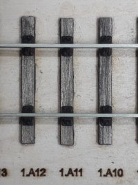
Example of OO-SF 1.6mm sleepers on top of a 3mm ply trackbed which just had sockets.
I used locator plugs to position the sleepers, then fixed jaw press fit chairs with rail threaded on.

The 3mm ply trackbase was to emulate 3mm cork.
20230916_104637.jpg
Steve
 
_______________
message ref: 10011
Hi John,
Try Hobarts, www.hobarts.com. There are plenty of others, but I've always had a good service from Hobarts, and they tend to be my go-to supplier.

By the way, I printed your chairs yesterday, and cut another set of timbering. This time in 2mm MDF as it was all I had to hand. Clearly not a good idea if I were building a layout, but good enough as an experiment.
I should have a complete 3mm turnout (minus rail) later today.

I must say how impressed I was with the printing of the chairs. As ever, they are a devil to photograph, especially so in 3mm scale, but nice all the same. It's not clear in the photo, but as you well know, these things are really tiny. :)

3mm chairs.jpg
 
_______________
message ref: 10014
Back
Top