Templot Club forums powered for Martin Wynne by XenForo :

TEMPLOT 3D PLUG TRACK - To get up to speed with this experimental project click here.   To watch an introductory video click here.   See the User Guide at Bexhill West.

  • The Plug Track functions are experimental and still being developed. Some of the earlier pages of this topic are now out-of-date.

    For an updated overview of this project see this topic.   For some practical modelling aspects of using Plug Track see Building 3D Track.

    The assumption is that you have your own machines on which to experiment, or helpful friends with machines. Please do not send Templot files to commercial laser cutting or 3D printing firms while this project is still experimental, because the results are unpredictable and possibly wasteful.

    Some pages of this and other topics include contributions from members who are creating and posting their own CAD designs for 3D printing and laser-cutting. Do not confuse them with Templot's own exported CAD files. All files derived from Templot are © Martin Wynne.
  • The Plug Track functions are experimental and still being developed.

    For an updated overview of this project see this topic.   For some practical modelling aspects of using Plug Track see Building 3D Track.

    The assumption is that you have your own machines on which to experiment, or helpful friends with machines. Please do not send Templot files to commercial laser cutting or 3D printing firms while this project is still experimental, because the results are unpredictable and possibly wasteful.

    Some pages of this and other topics include contributions from members who are creating and posting their own CAD designs for 3D printing and laser-cutting. Do not confuse them with Templot's own exported CAD files. All files derived from Templot are © Martin Wynne.

3D track - fun with laser-cutters

Quick reply >
@James Walters

Hi James,

I know nothing about laser-cutters, but I have worked EDM (spark-erosion) machines.

I'm wondering if laser-cutting of metal would be improved with a water-assist instead of air? (Or some other non-flammable liquid.) This would be much more effective at cooling, and washing away debris from the kerf line.

With the right equipment it needn't be any more messy than using cutting fluid (suds) on metal-cutting machines.

Martin.
An interesting idea Martin, but I suspect the cooling effect of the water would be too much, and the resulting steam might not be much fun for the laser either. I know nothing about EDM machines, but would love to have a play with one - I find them fascinating.
 
_______________
message ref: 11376
Can you use a laser cutter for thin ( ~0.8mm ) PCB materials such as FR4 ? The coating of copper is very thin so I suspect it may work but what about the board's inner material ? If it would work it has uses for the cutting of sleepers/timbers for soldered track construction.

Rob
 
_______________
message ref: 11377
So, I did a quick test today, to test the relative speeds of cutting 3mm plywood for timbering bases with each of the three power settings of the Falcon2 60w. Each was cut in a single pass and the results carefully measured 3 times to calculate the 'kerf'. Each test was cut from the same piece of material.

Results as follows:
22w 700mm/min @ 100% power 0.078mm kerf
40w 1100mm/min @ 100% power 0.085mm kerf
60w 1450 @ 100% power 0.11mm kerf

Each cut was clean, and each could have been run marginally faster, indeed I did get up to 1700mm/min with the 60w setting but found it left little wispy bits. Therefore, these results shouldn't be taken as the maximum speed, but seemed to be the optimal with the piece of material I was cutting at the time.

These tests confirm my suspicions that the only real advantage of the 60w machine for our purposes is the increase in speed. I'm not sure that justifies the relative cost increase.

The camera function of the Pro version is brilliant though.

Hope this little bit of nerdiness is of interest to some. I would certainly be interested to see how these values compare with other machines.

All the best,
James

Test Pieces 3mm Plywood.jpg
 
_______________
message ref: 11398
@James Walters

Hi James.

Very interesting, many thanks for that.

Does turning a 60W laser down to 20W produce the same results as a 20W laser at full power?

I can imagine that the 60W laser would have a larger diode with a wider beam and less precise focusing. This would be fixed by the optical construction, and wouldn't get any narrower simply by turning down the power?

Or not?

Martin.
 
_______________
message ref: 11399
The Creality machine has a stack of LED's all 6w (I believe), of which are all on for 60w. Selecting the 40 and 22w functions turns some off to reduce the power. Within those basic parameters the power output can also be controlled by the software between 1 and 100%.
So running the full 60w laser at say 33% power ought to produce results similar to a 20w laser.
In practice it doesn't seem to always work in a linear manner like that, and different materials can throw in additional variables.
It's another interesting thing to try out, I'll have an experiment when I'm next in the workshop.
 
_______________
message ref: 11402
I would certainly be interested to see how these values compare with other machines.
This is a 3mm LaserLite ply material test from my Comgrow Z1 Pro 20W. Running 2 passes for a cut as it seems to produce less surface scorching than 1 pass so I have been running at 700mm/min and 60% power. Thinking about preserving the life of the laser unit, although your last comment about power reduction, if it is achieved by turning off some LEDs in the stack then it won't help I'll just burn out one instead of half a dozen as I guess it'll just turn off the same LEDs each time. Might have to ask around and if it does power reduction by turning them all down I should be okay running at 60%, if they are just turning some off then I'd be better running at 100% to balance the life over all the LEDs.
IMG_0373.jpg
 
_______________
message ref: 11403
Hi James,
I have been watching these posts with interest but though it time to comment :)
If you have the time, could you run the same power output tests using the light burn power speed test?
The reason is not to find the power speed, but to make the machine do a series of small cutouts in the plywood.
I know that lightburn has speed and power compensation as is slows to travel corners, but I would be keen to see if the chances of ember burn increases with higher power, when your actually cutting out these smaller shapes. I have a concern as the power goes up so does the burn risk when cutting these smaller jobs.
The more power maybe just be a case of taking a sledge hammer (being too big a tool) to crack a walnut safely every time :)

It should also be noted for about 100 US you can also purchase the lightburn camera kit, which should do exactly the same job for a lot lower cost..
The cover is unquestionably a big advantage however.
Cheers
phil,
 
_______________
message ref: 11404
This is a 3mm LaserLite ply material test from my Comgrow Z1 Pro 20W. Running 2 passes for a cut as it seems to produce less surface scorching than 1 pass so I have been running at 700mm/min and 60% power. Thinking about preserving the life of the laser unit, although your last comment about power reduction, if it is achieved by turning off some LEDs in the stack then it won't help I'll just burn out one instead of half a dozen as I guess it'll just turn off the same LEDs each time. Might have to ask around and if it does power reduction by turning them all down I should be okay running at 60%, if they are just turning some off then I'd be better running at 100% to balance the life over all the LEDs.
View attachment 9525
Hi Rusty,
for what its worth
Thats my experience as well, in fact there are quite a few YouTube videos on this subject, and the consensus seems to be when it comes to cut quality, both in terms of soot and actual size of kerf. Little and often is better every time. one guy even advocates 1 pass per 1 mm of material thickness is the magic number.
Power and speed only come into play if you became a commercial outfit when actual cutting time also became a critical pat of the overall calculation.
cheers
Phil
 
_______________
message ref: 11405
The Creality machine has a stack of LED's all 6w (I believe), of which are all on for 60w. Selecting the 40 and 22w functions turns some off to reduce the power. Within those basic parameters the power output can also be controlled by the software between 1 and 100%.
So running the full 60w laser at say 33% power ought to produce results similar to a 20w laser.
In practice it doesn't seem to always work in a linear manner like that, and different materials can throw in additional variables.
It's another interesting thing to try out, I'll have an experiment when I'm next in the workshop.
Hi James,
I believe your exactly right, although the actual rating of a single LED seems to be closer to 5.5w (I am sure Creality are pushing the input power up a nudge to get over 5.5W output value and then round up to get there stated 6W value).

If you follow the trend of lasers you can easily see the first units were originally single LEDs of 5.5W rating then came 10W with twin LEDs using glass optic prisms to ensure the two output beams were exactly on the same focal point. Thus you get 2 x 5.5W of power combined - but a slight lose though the lens so =10W output power, 2 LEDs soon became 4 LEDs and you get 20W of power you also get a noticeable increase in both physical size and weight. (more LEDs and more importantly to weight increase more glass prisms required)

In addition to the number of LED in the laser head stack you can independent control the max Watt output of all the LEDs by using PWM protocols. as you say from 1 to 100% values are possible, but not truly linear.

What Creality seem to have done is expand the same theory by basically using three sets or stacks of nominal 20W units in the same laser head. Hence you can use the power control buttons to literally switch on or off 1, 2 or 3 banks of LEDs

Its a good Idea, the obvious down side it the total weight of the the laser head and thus the load the traverser system has to drive around, and likely the fact optimum efficiently must be lower at the 20W and 40W settings because these will still need to pass through all the glass prism banks. (assuming some power loss at each prism bank.)

This is one of the reasons why I question, if the extra power is in realty an advantage? especially if your also compromising on the load on your system, because of the extra weight of laser head your moving around. It sort of makes sense for full power, but less and less sense if your mainly using only 1 or 2 of the available LED banks.
Each to his own however, and I don't disagree if you have 60W of power avaible there will be times you can make use of it.

Its not for me though, I don't even see the need for the 40w unit on such a small X Y bed to be honest. I agree you can likely go a bit faster, but thats about it. Faster speed also in turn then puts more stress on your physical machine components, which has to ultimately impact on long term machine functionality and reliability.
I have noticed quite alarmingly the 22W Creality unit is no longer avaible in NZ. Currently we only have the 40W unit with the new 60W machine due to arrive late June I am told.
cheers
Phil,
 
_______________
message ref: 11406
I agree with the comments above, my test was to try to directly compare the cutting speeds of the different wattages to try to get a comparative result. I will note though that an advantage of a single pass is less over-burn on the surface of the material. I based my speed settings on achieving clean cuts to both the cut edges and the top surface. If you look at the picture I posted you'll see the surfaces are very clean.

Phil, yes. I'll run the lightburn tests at the different power settings when I'm next in the workshop, probably Monday now.
I've not noticed any unwanted burning on the lightburn tests I've done so far, but then I've not really been looking at that aspect, so I'll test with that specifically in mind.

Personally, and having the experience/nightmare of seeing a Co2 laser tube as a consumable, I don't see the longevity of the laser diodes as being an issue. Sure they will fail over time, but the lifespan does seem to be much more than a Co2 tube, and certainly a lot less hassle to replace. I suspect it wont be long before an outfit sets-up to replace diodes when they fail.
Cutting at reduced power and slower speeds might prolong the life of the diodes, but will increase the wear and tear on the mechanical elements of the machine. I know which I'd prefer to replace.

In my opinion a failing of the 60w machine is that it's speed is limited to that of the 22w and 40w machines, probably as you suggest Phil because it has to drag a greater mass about in the laser head. If it had the top-end speed increased by say 30%, and had 10mm belts instead of the 6mm ones and polished guide rails such as with the Atomstack machine I reviewed, then the extra power could be better utilised to engrave faster which can be very tedious. I think these modifications would justify the extra spend.

That said, I think Co2 is the better option for engraving anyway as upper and lower power settings can be set which enables greyscale engraving to be truly 3d, which is really good for doing stone textures. But, as we're not engraving our timbering bases it makes no difference here.

The main point being that 20W (and probably 10W) is ideal for our needs.

Best,
James
 
_______________
message ref: 11407
Hi James,
Totally agree with you power wise 10 to 20~22 W is actually the optimum for 4 and 7mm railway parts being cut. I also agree faster speeds and the Co2 laser options more come into play for engraving purposes. For me at least, from what I am doing, or in truth still trying to do. Cutting is more important than engraving.

Just to be clear my point about wear and tear was not so much at the LED laser head, but the excess load more mass has on the other mechanical parts of the system.
Are Creality still also using the NEMA 17 steeper motors? thats my biggest concern, I.e. missed steps, which with my set up goes directly to X Y accuracy, or the lack there of.

Its a question of which is worse, more work done by the system ( I.E. more passes) or more stress put on the system (I.E. more mass to move about). I can't answer that question, but I would suspect there is a clear tipping point somewhere.

Personally I think its a case with Creality of, talking about more power equals more sales, but there has to be a practical limit to that approach..
Cheers
phil
 
_______________
message ref: 11409
But, as we're not engraving our timbering bases it makes no difference here.
Sticks hand up here - actually yes I am (just to be awkward!). Just drawing it up at the moment for the next experiment. I'm not that keen on the "nibs" on the ends of the sleepers so I'm drawing up the sleeper template changing it with a "half etched" connector underneath the rail so that I can hide it when adding the ballast.
 
_______________
message ref: 11411
Sticks hand up here - actually yes I am (just to be awkward!). Just drawing it up at the moment for the next experiment. I'm not that keen on the "nibs" on the ends of the sleepers so I'm drawing up the sleeper template changing it with a "half etched" connector underneath the rail so that I can hide it when adding the ballast.
Hi Rusty, You could increase the width of the nibs and etch halfway down the ends of the sleepers/timbers. This should hide the cut nib/timber below the ballast. I'm laser cutting some timbers today and will post results later.
 
_______________
message ref: 11412
Hi Rusty, You could increase the width of the nibs and etch halfway down the ends of the sleepers/timbers. This should hide the cut nib/timber below the ballast. I'm laser cutting some timbers today and will post results later.
Very true, point remains though that were are still etching the sleepers, I was going for the under rail nibs so that I could interleave the straight panels to get more sleeper panels out of a sheet of plywood.
 
_______________
message ref: 11423
Assuming you need 60 foot track panels, just output one 60 foot track panel of your desired configuration, with nibs & snibs switched off.
Then use a 2d program like inkscape to arrange that one panel on your chosen bed size, so that when cut and removed the residue will act as an assembly jig. Then copy that panel to another area on your bed, but then concatenate the sleepers so that adjacent sleepers share the same cut lines & delete the duplicate cut line for efficiency. Then copy the concatenated panel as many times as will fit on your bed to maximise ply usage.
1717174223124.png

example of concatenated P4 sleepers, but perhaps I should use the term Bunched , as I believe Martin might eventually provide a Bunch function in a galaxy in the far distant future

the example shows KERFSOCK layer in blue, and the KERFTIMB layer in green.
Steve
edited to correct typos and add example
 
_______________
message ref: 11424
Last edited:
.
Another day, another laser cutter. It seems a lower power makes a narrower kerf, which is a good thing for accurate dimensions. Also a narrower cut obviously means less material to be burnt away, needing less power for the same material thickness.

As so often, I needed to slow the playback speed to make sense of the fast commentary. What's the rush?


Martin.
 
_______________
message ref: 11445
It seems a lower power makes a narrower kerf,
Hi martin,
In my honest opinion that video is a little bit deceptive,
to start with when it comes to laser kerf I have found it best to envisage a taper milling tool of say 10 degrees inclusive angle. The point being the deeper you cut into the work piece in a single pass the wider the gap is at the top in relation to the gap at the bottom.
It is also true more powerful machines also do have a bigger laser point, analogist to a bigger taper cutting tool.
This seems to be a side effect of the number of prisms used to concentrate all the LEDS.

Multi passes have the strange effect of starting the cut again, thus you get a sort of saw tooth shape rather then a true vee shape.
Although this is not happening in reality, its similar in milling parlance to doing a shallow cut, then stepping the tool out further from the cutting path before dropping the z axis. Hence the saw tooth analogy. This is the reason so many people say multi passes are more accurate than a single pass.

Cut depth and cut speed are also important considerations, it follows that more power therefore allows for both deeper and faster cutting.
Just like cutting with a machine tool there are optimum feeds, but unlike a machine tool the feed is related to the power of the laser not the cutting rotation speed or number of teeth on the cutting tool.

The other thing which is very important, is the correct focal point, its generally acknowledged for cutting, the correct value should be with the focal point set at exactly 1/2 the thickness of the work and for engraving the focal point should be on the top of the work to be engraved.

what is less understood is the stated value of the manufacture is really only a general guide. This becomes even more hit and miss with such a crude setting device as that shown in the video.

A very good way to check the correct focal point although quite complicated to set up, is to have a test piece of wood at a known angle say 4 mm height difference over a 300 mm length of the test piece. Then by running straight line cut you can actually see the kerf will go from wider to narrower and then wider again.
The narrowest point being the optimum focal height. the only problem is accurately working out what height the laser head was above the work piece at that time. This is best done by not move the z height at all once the cut is complete, don't move the test piece either, simply observe the narrowest point and mark it. then move the laser back over the mark and measure from this mark to say the underside of the safety shroud, by using a known block size and feeler gauges. once you have this value thats your optimum focus at the top of every work piece.

If you have lightburn which is about the best laser control software there is, A key tool for starting and understand you new laser is the Material test Generator. You do this only after find the optimum focal point of your laser however.

I know experienced users often don't use this tool, but that is simply because they have enough experience to start beyond this key test tool. In truth it is simply a matrix grid where the speed and power can be increased in steps, the idea being once completed you check the test piece by both measurement and visually, and simply use the setting that both look and measure out the best.

All that said for cutting wood up to say 4 mm thick then the most cost effect options are very much the machines in the 10 to 22W power range. More power only really gives you more speed, and potentially more longer term problems.

For engraving (not so much part etching) much faster speeds are better, so more powerful lasers can come into there own.
The real key is once you have a laser, quite a bit of playing around first is required if you want to get the very best out of your machine.
cheers
Phil,
 
_______________
message ref: 11446
In my honest opinion that video is a little bit deceptive,
to start with when it comes to laser kerf I have found it best to envisage a taper milling tool of say 10 degrees inclusive angle.
@Phil G

Hi Phil,

This surely depends on the focal length of the lens? With a longer focal length the angle of the beam each side of the focal point will be narrower. Also the quality of the lens in focusing the beam to a single focal point is surely important. Perhaps the online discussion of laser cutters should be concentrating a bit more on the quality of the optics and a bit less on power and feed rates?

When using multiple cuts, does the head drop between each cut? It's a bit misleading to compare it with a milling cutter if that doesn't happen. If I added a laser head to my desk-top CNC miller it would be possible to do that -- is it supported in the software?

cheers,

Martin.
 
_______________
message ref: 11447
@Phil G @James Walters

An interesting metric to compare on laser cutters would be focused power per square mm, although I don't recall this being quoted.

In the above review, the optimum kerf offset is given as 0.055mm. i.e. a kerf-width of 0.11mm. For other laser cutters I've seen, the kerf-width is often quoted as 0.2mm (0.1mm offset). Some simple calcs gives:

10 Watt laser with 0.11 mm kerf-width = 1052 Watts/sq.mm.
20 Watt laser with 0.2mm kerf-width = 637 Watts/sq.mm.

In other words the 10 Watt cutter has a much higher focused power into the cut than the 20 Watt laser. I'm not clear whether the quoted power figures refer to input or output power, but either way the difference will be comparable.

To get a smaller kerf-width requires better quality lenses. For our purposes requiring precision cuts it might be worth spending more on a laser with better optics than one with more power.

Also a screw adjustment for the focusing height would be worth having, and some means of tramming the bed to ensure the focused height is constant all over.

Or not?

Martin (looking at his CNC miller).
 
_______________
message ref: 11450
As so superb demonstrate by James. There are certainty a lot of uses for a laser, other then the obvious making sleeper's and crossing timbers.
well done James,
cheers
Phil,
 
_______________
message ref: 12031
Hi James,
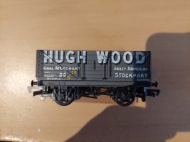
just out of interest, do you think it would be possible to crate a paint stencil from say paper or 1 mm Medite, with a laser? I am not sure which would be the best approach to take, use as say the photo as as SVG then easily engrave. Or or create a DXF path in say a cad or light burn?
what are your thoughts? Also how small do you think it could create a stencil? if we take the photo the Hugh Wood
should be easy achievable, but what about the empty to Grassmoor colliery? is that do able in 4mm scale?
maybe a good idea for an other of your great you tubes videos if its even doable..
cheers
Phil
 

Attachments

  • 20240721_101918.jpg
    20240721_101918.jpg
    6.9 MB · Views: 6
_______________
message ref: 12039
Hi Phil,

I think a stencil would be do-able, especially with the 1.6W laser unit for the Falcon2. I'd probably opt to use PET film, I've used 0.1mm PET from Amazon for this sort of job and it works well. Another option which I think would also work is laser cutting frisk masking film such as is sold for airbrush artists. I haven't tried it, but I think it would work. The problem with stencils are the 'counter points', that is the little bits inside letters such as lower-case e,a,b, etc. and of course some upper case letters such at A's and O's. Getting the stencil to form cleanly around ironwork etc might also be tricky.
I think though that on balance I'd prefer to use decals rather than faff with stencils.

Coincidently, I've been giving some thought to lettering on wagons, specifically the SECR on the side of my hopper wagons which you may have seen me produce recently. Decals would obviously work, but they're fiddly, can be inconsistent, and in my hands often disappointing, so I'd prefer paint.
My proposed method is to engrave the artwork into a stainless steel sheet and use a variation of the pad printing technique to transfer the image, by filling the engraving with paint/ink, and then picking it up with a pad and transferring it to the wagon side. Ideally I'd get a cheap pad printer for the job, but I'm going to try free-handing it to begin with.
I think a diode laser will engrave the stainless sheet sufficiently, although I suspect it may warp. Fortunately, I've been sent a MOPA fibre laser to test which should do the job a treat and it's on my list of things to try out.
Another motivation for this is that I've made 50+ Midland 5 plank wagons, all of which need MR on each side. This will get expensive in transfers and bore me to insanity to fit. I think that with a simple jig I could letter them all in less than an hour by pad printing.

Another option which I've seen work really well but not tried myself is UV printing. If you have the artwork then finding a local company which does UV printing might be worth considering.

All the best,
James
 
_______________
message ref: 12042
Back
Top