Templot Club forums powered for Martin Wynne by XenForo :

TEMPLOT 3D PLUG TRACK - To get up to speed with this experimental project click here.   To watch an introductory video click here.   See the User Guide at Bexhill West.

     Templot5 - To join this open-source project on GitHub click here.  For news of the latest on-going developments click here.  Templot5 is now included with Templot2 - download.

  • The Plug Track functions are experimental and still being developed. Some of the earlier pages of this topic are now out-of-date.

    For an updated overview of this project see this topic.   For some practical modelling aspects of using Plug Track see Building 3D Track.

    The assumption is that you have your own machines on which to experiment, or helpful friends with machines. Please do not send Templot files to commercial laser cutting or 3D printing firms while this project is still experimental, because the results are unpredictable and possibly wasteful.

    Some pages of this and other topics include contributions from members who are creating and posting their own CAD designs for 3D printing and laser-cutting. Do not confuse them with Templot's own exported CAD files. All files derived from Templot are © Martin Wynne.
  • The Plug Track functions are experimental and still being developed.

    For an updated overview of this project see this topic.   For some practical modelling aspects of using Plug Track see Building 3D Track.

    The assumption is that you have your own machines on which to experiment, or helpful friends with machines. Please do not send Templot files to commercial laser cutting or 3D printing firms while this project is still experimental, because the results are unpredictable and possibly wasteful.

    Some pages of this and other topics include contributions from members who are creating and posting their own CAD designs for 3D printing and laser-cutting. Do not confuse them with Templot's own exported CAD files. All files derived from Templot are © Martin Wynne.

Extracting a 3D timbering brick from a track plan

Quick reply >
Hi Martin

I've just spotted another glitch - a rogue chair. Might be me, of course, forgetting to tick or untick something!

rogue_chair.PNG


In the STL export, this manifests as a "negative" chair socket floating in the air, rather like a building brick. I've traced it to template 7 in the attached box file - also attached is the shapes file. The STL file attached is the fixed version.

This timber brick is printing as I'm writing this - I just added supports under the chair to keep the printer happy so I'm not too bothered by it as I can just break it off, but I thought you ought to know about it.

What I did notice that when I was I opened the shove timber box, selecting any timber under the rogue chair changed the position of the blue line under that chair.

Cheers,
Paul
 

Attachments

  • bricks_2022_05_14_1051_34.box
    169.3 KB · Views: 205
  • bricks.bgs3
    21.1 KB · Views: 195
  • brick2 - to print.stl
    1.3 MB · Views: 238
_______________
message ref: 4281
@Paul Boyd

Hi Paul,

I'm appointing you Glitch-Finder-In-Chief. :)

paul_glitch_chair.png


That chair is on the B2 timber. Because it is a bonus timber it is picking up chairs on rail 4. You can remove it by unticking chair 4 on the timber.

Alternatively, on that template you could restore timber E1 and shove it along to the B2 position instead of using a bonus timber.

I didn't give bonus timbers much thought in the chairing process, so that's something I need to look at. Thanks for finding it.

The blue lines on the chairs on the control template show the keying direction and amount of key offset on the chair. Only the direction and offset, the actual key is on the other side of the rail. You can change the direction using the flip keys boxes on the dialog. The blue lines dance about as you use mouse actions (or press or hold down F12) because the key offset is randomised. The amount of offset and randomising can be changed. That's not fully working on turnout timbers yet, only plain track sleepers, and I haven't thought about what happens for the RG and FG dummy chairs.

Thanks again for finding the glitch.

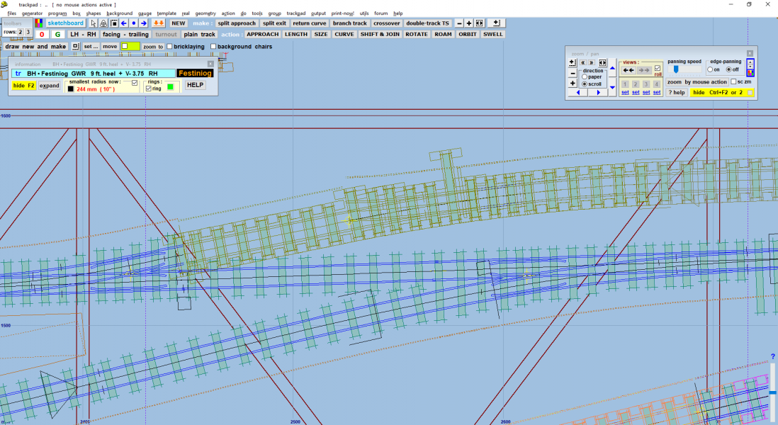
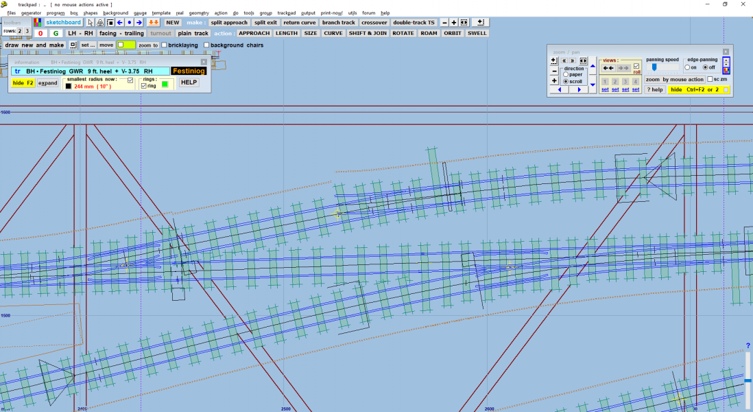
paul_screen.png


p.s. that screen is an amazing confection in Templot! I never dreamed to see such things when I started scribbling on bits of paper 40 years ago. :)

Hope the brick printing turns out fine. Let us know.

cheers,

Martin.
 
_______________
message ref: 4282
p.s. Paul,

I'm thinking of a duplicate clip function. To make copy of an existing clip from another brick, changing the gender and colour to match the current brick. Any thoughts?

At present it would be very easy to print a brick, and then find the clips missing because you forgot to change the settings for the shared clip.

cheers,

Martin.
 
_______________
message ref: 4283
p.s. Paul,

I'm thinking of a duplicate clip function. To make copy of an existing clip from another brick, changing the gender and colour to match the current brick. Any thoughts?

At present it would be very easy to print a brick, and then find the clips missing because you forgot to change the settings for the shared clip.

cheers,

Martin.

Hi Martin

I've now fixed the rogue chair - in fact, chair 2 seemed to be a duplicate as well. So it was something I hadn't unticked! The print has just this second been taken off the bed, and the next three bricks are now being printed together. The second brick (the orange one) printed very well. I've found that end and side clip clearances of about 0.13mm work well. I sliced this in Prusaslicer and printed from there via OctoPrint running on a Raspberry Pi. I thought I'd compare slicing with Cura version 5 but it just complained that it was too big for the bed - no it isn't!

A duplicate clip function is something I was thinking of asking for, but I felt I'd asked for enough things already! Yes please, I would find that very useful, especially if there was also a way to show each half of the clip in its own colour. As it stands now though, it's only a matter of a few clicks to change gender/colour so not too onerous. The main issue is actually remembering to do it, and I have picked up one or two where I'd forgotten, but spotted on the STL

A few other observations:-
  • I find the Alt-Home shortcut very handy when trying to make sure I'm picking up the underlying template to copy to a new one.
  • The RGB labels on the screen are very useful, especially when making sure I've picked the right colour to change the clip!
  • I've found the labels print better at 6mm width. 5mm is ok, but at the default 4mm I found the letters vanished when sliced.
Is anyone else printing timber bricks yet?

Cheers,
Paul
 
_______________
message ref: 4284
Printed and trial positioned! The brick near right won’t have rails on to represent lifted track, and it’ll also be cut a bit shorter. I printed two versions of that brick - one with flat tops and the other with recesses to represent chair indentations. The jury is still out on that…

B741CD03-C3BB-412E-A413-4D7D70574430.jpeg


EA51FBFB-A405-4AC6-8118-C4B0D6788B7B.jpeg
 
_______________
message ref: 4285
@Paul Boyd

Hi Paul,

Looking good! How long did the print take? Is there any reason for using a light-coloured polymer for the timbers instead of grey/brown? Is paint on the polymer resistant to scratching to reveal the light colour? Or does the prototype have sun-bleached timbers? If it's in the Ffestiniog area I find that hard to believe. :)

How dimensionally stable is the jig-saw after assembly? It occurred to me that if some additional triangulation was added, like this:

paul_bricks_mod.png


it would be acceptable to have less closely fitting clips? Or maybe that's unnecessary and over the top.

I'm going to do something about the unwanted rails (blue here) on plain track, which confuse the brick colours. Also having the MS flag in brick colours is confusing. I will do something about that too.

A duplicate clip function is something I was thinking of asking for, but I felt I'd asked for enough things already! Yes please, I would find that very useful, especially if there was also a way to show each half of the clip in its own colour.

Ask away -- two heads are better than one. Having each half of the clip in its own colour would be a blindingly obvious improvement, and does away with the need for the dot symbol.

Is anyone else printing timber bricks yet?

I think we have scared them off with the complexity of all this! I'm still not convinced that I have done this the best way, merging with the background shapes functions, and duplicated background templates. I thought it would save work to use the existing shape drawing and template blanking functions, but it might have been better to start with a blank sheet and create something completely new and separate. Or maybe using the sketchboard instead of the background shapes -- although Nils's code for the sketchboard engine is quite fragile and easily wrecked if I start kludging too many extra functions into it.

But that does also raise the question of adding sketchboard items into the FDM print -- how about the walls of the engine shed included in the brick?

Also I'm wondering about including platforms in the brick? They would have a lot of joints, but could be smoothed over with filler. The slicers could add supports inside a hollow platform. Or maybe a separate platform print with a very low-density fill which clips alongside the track? It would save all the platform spacing and height adjustments after track laying.

Too many ideas. :)

cheers,

Martin.
 
_______________
message ref: 4286
Hi Martin

Looking good! How long did the print take? Is there any reason for using a light-coloured polymer for the timbers instead of grey/brown? Is paint on the polymer resistant to scratching to reveal the light colour? Or does the prototype have sun-bleached timbers? If it's in the Ffestiniog area I find that hard to believe. :)

It was something like a total of 5-6 hours for two prints, which covered the four bricks that don't so far have rails. The white was simply because the Evergreen strip used on the section already built was white, so I thought it best to keep a common base colour. I'll maybe use a grey plastics primer from Halfords which should should give better adhesion for the colour. I did look at getting some grey PLA, and there is another section of bullhead unconnected to this bit which I may well do in grey just to see how it looks. Most definitely not sun-bleached in North Wales!

How dimensionally stable is the jig-saw after assembly? It occurred to me that if some additional triangulation was added

Dimensionally it was surprisingly accurate! The formation placed is 1m long including the plastic strip timber section, and without any "adjustment" of the length I reckon its maybe 1mm longer than the plan, and I'm not going to try to work out where that millimetre has come from! Widthways, with no play in the clips, the extra splices you've shown I don't think are necessary. The blue template, not having any rails, is less critical anyway and will probably actually be cut in half. It's intended to represent what was a junction off the main line.

I'm going to do something about the unwanted rails (blue here) on plain track, which confuse the brick colours.

I agree that the unwanted rails are confusing!

Having each half of the clip in its own colour would be a blindingly obvious improvement, and does away with the need for the dot symbol.

I was mulling over that and wondering if the duplicate could be linked in some way to the original? I can see the possibility of someone adjusting the size or position of one clip and not the other, although if the two halves are shown as different colours it should be obvious. I deliberately choose contrasting colours on adjacent bricks but I can see larger layouts running out of contrasting colours so it would be less obvious!

I think we have scared them off with the complexity of all this! I'm still not convinced that I have done this the best way, merging with the background shapes functions, and duplicated background templates.

With so many options, I think complexity is unavoidable! I'm happy with doing this as background shapes, especially with the ability to save a separate shapes file for brick shapes. I've not done that (this shapes file only contains brick templates) but notice that you've prefixed the layout name with 'bricks' - excellent! When I first started playing with this I made a copy of the original box file to cover with brick templates, but now with the ability to show/hide bricks or show only bricks that's not necessary. I don't regard brick templates as duplicates but as having a different function.

At one point I'd saved the bricks as a separate box file, then later opened the full layout and had only brick templates showing - I managed to confuse myself as to which file I was working on! (and in this case, I was working with files in the Windows sense, not something I always do with Templot). I think for me the answer is that I don't ever need to save a separate bricks file! Shapes files though, I do prefer separate files, of which the brick shapes are one, so I can build up the various shapes on the trackpad from multiple files as required.

But that does also raise the question of adding sketchboard items into the FDM print

I don't use the sketchboard so less sure about that, but it sounds like it makes sense I'm guessing you just mean footprints of buildings or whatever!

Also I'm wondering about including platforms in the brick? They would have a lot of joints, but could be smoothed over with filler. The slicers could add supports inside a hollow platform. Or maybe a separate platform print with a very low-density fill which clips alongside the track? It would save all the platform spacing and height adjustments after track laying.

Hmm... Platform height? Overhangs? I'm not sure that's a feature I'd use. What could be useful is the platform edge line from a template that has that to use as a distance guide from the track. I can't quite visualise how that would look, and I wouldn't want a solid web between the platform edge and the timbers. I know we can now use slabs for the same thing though, which I think is sufficient - it doesn't really need to be a continuous line.

I've still got two more sections of plain track to turn into bricks so that's the next step. I also need to have a look at slightly bulged corners in the prints, which is why the edge/side clearances are maybe higher than you'd expect. It's only in the region of about 0.1mm though so it wasn't something I was too concerned about but I'd like to get it sorted. Apparently people print test cubes to optimise this sort of thing!

Cheers,
Paul
 
_______________
message ref: 4287
Having each half of the clip in its own colour would be a blindingly obvious improvement, and does away with the need for the dot symbol.

@Paul Boyd

Hi Paul,

Here we go:

new_clips1.png


If there is no duplicate clip on a different brick, the outline shows empty:

new_clips2.png


I've found the labels print better at 6mm width. 5mm is ok, but at the default 4mm I found the letters vanished when sliced.

There is something odd going on -- your 7-seg characters are much larger than the ones on my test bricks. They definitely fit on 4mm wide tabs here. :confused: I will sort it out.

Hopefully I will get 234c out in a day or two.

cheers,

Martin.
 
_______________
message ref: 4288
@Paul Boyd

Hi Paul,

There is an issue with the slicing:

slicing_issues.png


I've noticed some weakness in the finished bricks, where the brick snaps easily through the webs. Looking at the underside of the Cura preview it easy to see why (the above is actually one of yours, but mine are the same).

There are a few places where the web is a separate island, not connected to either of the adjacent timbers (purple rings), and several other places where the web is not connected to one timber. If these occur opposite each other (pink rings) the brick will easily snap apart at that location.

It's difficult to know whether to blame Templot, or the online repair tool, or the slicer, and whether changing the slicer settings might prevent it.

However, it happens only on curved track. Straight track is fine. Which makes me think it might be related to rounding effects in the STL export after the curving calculations.

Does your slicer produce similar results? Mentioning it now to warn you to be careful handling your brick prints!

I'm going to experiment with the web and flange dimensions to see if I can cure it.

But not today, because I have 288 bedding plants to install in a community garden here. :)

cheers,

Martin.
 
_______________
message ref: 4289
@Paul Boyd

Hi Paul,

There is an issue with the slicing:

View attachment 3692

I've noticed some weakness in the finished bricks, where the brick snaps easily through the webs. Looking at the underside of the Cura preview it easy to see why (the above is actually one of yours, but mine are the same).

There are a few places where the web is a separate island, not connected to either of the adjacent timbers (purple rings), and several other places where the web is not connected to one timber. If these occur opposite each other (pink rings) the brick will easily snap apart at that location.

It's difficult to know whether to blame Templot, or the online repair tool, or the slicer, and whether changing the slicer settings might prevent it.

However, it happens only on curved track. Straight track is fine. Which makes me think it might be related to rounding effects in the STL export after the curving calculations.

Does your slicer produce similar results? Mentioning it now to warn you to be careful handling your brick prints!

I'm going to experiment with the web and flange dimensions to see if I can cure it.

But not today, because I have 288 bedding plants to install in a community garden here. :)

cheers,

Martin.

Hi Martin

I would suggest the problem is Cura! The attached photo and screenshot shows the underside sliced with Prusaslicer and it's absolutely fine - in fact, Cura seems to have made a right pig's ear of it! I don't really like Cura and have had better results with other projects (with the same STL) with PrusaSlicer. One thing Cura does have that I miss is a hole size expansion setting - with PrusaSlicer my hole size expansion is a drill bit because I refuse to draw the holes oversize! The Templot STL file was fixed using the link in Templot.

Regarding the 7-seg display, the characters expand to fit the width and do fit perfectly on a 4mm wide tab on the screen. I suspect that when slicing, the individual segment widths become too small to print. 6mm wide is probably a bit big, especially as 5mm prints the characters fine. I think there's a "thin wall" setting somewhere but I haven't explored that.

Those clips look excellent!! I'm hanging on for 234c before getting on with the rest of the bricks - there's plenty to be doing on the actual layout now I've got more bricks printed.

Cheers,
Paul

slicer.PNG
IMG_0446.jpg
 
_______________
message ref: 4290
Just for interest, I sliced exactly the same STL with Cura 4.13.1. I think it's clear where the problem is, but whether there's a setting that can be changed I don't know. However, I notice that my Cura slicer has diagonal lines, but much more pronounced breaks, than yours so that suggests there probably are things that could be changed.

Cura slicer.PNG
 
_______________
message ref: 4291
@Paul Boyd

Hi Paul,

Rain stopped play on the gardening, so I'm back on the computer. :)

Yes, in Cura I had concentric set for the bottom layer fill instead of lines. Concentric is supposed to provide better bed adhesion and less warping.

Tried lines instead, but same result for Cura, as your result.

Looking close-up at the STL, I can see the problem. This is, or should be, the join between the web and timber flange on some sharply curved track, but there is a gap between them:

slicing_issues1.png


That's an extreme close-up, the gap is about 0.005mm or 2 tenths of a thou. The much smaller gap in the double line is the difference between the top and bottom edges of the timber flange.

There are several settings in Cura to smudge over such small gaps, although the results are likely to be a bit unpredictable. Also I need to test each of several such options to see which is the most effective.

All this is caused by rounding effects in the STL export. STL files are currently being exported to 3 decimal places of mm. DXF files are exported to 4 decimal places for mm, and 6 decimal places for inches.

I restricted the number of decimal places because being text files, it has a direct effect on the file size. But I think they need to be increased. I don't want to go to the binary versions of STL because it makes the files unreadable for finding issues.

Also it would probably be better to program a small overlap at the join, and leave the online repair tool to sort it out.

I have now installed PrusaSlicer to see how it compares. It is based on Slic3r which I tried once before and didn't have much success with. Time to try again.

cheers,

Martin.
 
_______________
message ref: 4292
@Paul Boyd

Hi Paul,

Rain stopped play on the gardening, so I'm back on the computer. :)

Yes, in Cura I had concentric set for the bottom layer fill instead of lines. Concentric is supposed to provide better bed adhesion and less warping.

Tried lines instead, but same result for Cura, as your result.

Looking close-up at the STL, I can see the problem. This is, or should be, the join between the web and timber flange on some sharply curved track, but there is a gap between them:

View attachment 3700

That's an extreme close-up, the gap is about 0.005mm or 2 tenths of a thou. The much smaller gap in the double line is the difference between the top and bottom edges of the timber flange.

There are several settings in Cura to smudge over such small gaps, although the results are likely to be a bit unpredictable. Also I need to test each of several such options to see which is the most effective.

All this is caused by rounding effects in the STL export. STL files are currently being exported to 3 decimal places of mm. DXF files are exported to 4 decimal places for mm, and 6 decimal places for inches.

I restricted the number of decimal places because being text files, it has a direct effect on the file size. But I think they need to be increased. I don't want to go to the binary versions of STL because it makes the files unreadable for finding issues.

Also it would probably be better to program a small overlap at the join, and leave the online repair tool to sort it out.

I have now installed PrusaSlicer to see how it compares. It is based on Slic3r which I tried once before and didn't have much success with. Time to try again.

cheers,

Martin.

Hi Martin

I haven’t got as far as trying different styles of bottom layer, so that’s new to me. I believe ABS is more susceptible to warping so that sounds a useful thing to know if I ever I use ABS - I thought I may have to for the bricks but it transpires that butanone is fine as a solvent for PLA. Well, Anycubic PLA at least!

I don’t think file sizes are an issue these days, within reason. My biggest brick is a few hundred K, if bricks were a few Meg I don’t think anyone would notice! If another decimal place sorts it, go for it!

I’m also guessing that there’s a setting in PrusaSlicer that tells it to ignore gaps smaller than a certain size. Mostly though, I’ve just used Prusa’s default settings for the printer and filament which seem to work very well. I’m a bit wary of fiddling too much!

Cheers,
Paul
 
_______________
message ref: 4293
@Paul Boyd

Hi Paul,

I tried first adding overlaps everywhere, so that even when sharply curved (this is a silly 300mm radius in EM) there is no risk of gaps appearing anywhere. Which avoids the problem of knowing how many extra decimal places of precision would be needed to be safe.

overlaps_for_cura2.png


This is the exported STL, which looks messy:
overlaps_for_cura4.png


But the mesh repair tool seems happy enough to accept that, and returns this, which looks horrible:

overlaps_for_cura1.png


But it's all meat and drink to Cura, which happily creates this:

overlaps_for_cura3.png

Which seems to have fixed the problem. :)

So now there are another 2 new settings:

web integrity overlap
flange integrity overlap

both of which default to 1/4" scale (0.08mm at 4mm/ft) but can be set to zero if not wanted.

• They will need to be set to zero if a timbering fret (3D assembly template) is wanted.

Will be in 234c shortly. But first I need to print it on BIBO just to be sure.

cheers,

Martin.
 
_______________
message ref: 4294
Excellent - something else sorted (and more options to document :) ).

Looking at the 'concentric' output, I can see how that could reduce any warping as the heated plastic is distributed more evenly. Maybe it's time to explore some of the other options!

Cheers,
Paul
 
_______________
message ref: 4295
@Paul Boyd

Hi Paul,

Printed fine:

webs_integrity1.jpg


All Templot export settings on the defaults (EM gauge). Timber tops given a quick rub over with a 320-grit sanding block (wet, soapy water) while still on the flat glass plate, which makes it easy to hold.

Usual cruel close-up shows a few strings on the plate while printing the first layer. The socket holes add a lot of travel moves -- I use a higher temperature for the first layer (205 degs), so stringing is more evident:

webs_integrity2.jpg


p.s. those 7-seg characters are the default size, 3.2mm high on a 4mm tab. They are easily readable -- if your slicer is rejecting this you may have the small-detail filter set a bit too aggressive? Sleepers are 3.3mm x 34.0mm.

But I agree the characters could be bigger without any problem. I will change the default to 15" (5mm in 4mm/ft scale).

All seems ok. Back to the clip pairing code. :)

cheers,

Martin.
 
_______________
message ref: 4296
I think it’s time to play with some slicer settings!
@Paul Boyd @AndyB

Hi Paul, Andy,

Have you seen the froth about the recent Cura 5 upgrade? It seems they have rewritten the slicing engine to improve fine detail.

When I mentioned a while ago that it's possible to print fine detail with a larger nozzle by reducing the extrusion volume, not everyone was convinced. But now Cura is claiming to be printing 0.1mm thin walls with a 0.4mm nozzle:


Anyone tried it yet?

cheers,

Martin.
 
_______________
message ref: 4339
Hi Martin,

I installed v5 a little while ago but haven’t really explored it yet, preferring PrusaSlicer. However, I’m already aware that Cura has features that PS doesn’t, and it seems v5 will be even better for some things! I printed a 54mm figure with v4 and wasn’t really happy so it’ll be a good one to do a comparison with.

In the second video he mentions that the UI is still buggy - it’s the Cura UI I really don’t like, and I’ve also had some other issues. I will give v5 a go though to see what the end results are.

Cheers,
Paul
 
_______________
message ref: 4346
I'm hanging on for 234c before getting on with the rest of the bricks
@Paul Boyd

Hi Paul,

234c is now on the server. :)

Select an existing clip, make sure to change the colour in the marker panel and tick the box, then:

paired_clips.png


A matching opposite clip is added. Any subsequent changes to the size or position of one of them will be reflected in the other.

Changing the gender from tommy bar to claws also swaps the direction.

cheers,

Martin.
 
_______________
message ref: 4364
Hi Martin,

That looks exciting! I'll have a play shortly. I got distracted on my layout by a couple of turnouts on the laid flat-bottom sections that just looked wrong so have rebuilt those before the section made with timber bricks gets in the way! Also distracted by the electronics side of the layout - I'm using MERG CBUS which is probably overkill but of as much interest to me as other aspects of the layout! (although in my professional life at the moment I'm fed up with electronics, or more specifically trying to work around ridiculously long lead times or a flurry of discontinued parts.)

Cheers,
Paul
 
_______________
message ref: 4366
@Paul Boyd @AndyB

Hi Paul, Andy,

Have you seen the froth about the recent Cura 5 upgrade? It seems they have rewritten the slicing engine to improve fine detail.

When I mentioned a while ago that it's possible to print fine detail with a larger nozzle by reducing the extrusion volume, not everyone was convinced. But now Cura is claiming to be printing 0.1mm thin walls with a 0.4mm nozzle:


Anyone tried it yet?

cheers,

Martin.
Hi Martin

As I'm writing this, I'm printing some bits that were sliced in Cura 5. Two things I've noticed immediately (and the profile is unchanged from that used in Cura 4) is that there are far fewer retracts, and hole walls are attached to the rest of the model far more securely. Previously it was almost as if each hole was basically a tube barely attached to the rest of the print. I still don't like the UI though :) Each slicer of the two I have has its own benefits and drawbacks so I will use both, but mainly PrusaSlicer - apart from anything else that works with my SpaceMouse Compact and talks nicely to OctoPrint!

I've also had a play with the paired clips - just on the parts already printed for now. That works so well! Because I had clips scattered throughout the existing shapes file, the paired clip got separated from the original (although I know I can shuffle the list order). For new bricks, creating the clip and its pair at the same time will keep them together. I've not had a chance yet to spot any other new features for 234c.

Cheers,
Paul
 
_______________
message ref: 4373
@Paul Boyd

Hi Paul,

I haven't actually tried Cura 5 yet, so I will see what it does with some of my files. :)

For new bricks, creating the clip and its pair at the same time will keep them together. I've not had a chance yet to spot any other new features for 234c.

My intention was not to create both paired clips at the same time. The idea is that after extracting the first brick, you change the colour and start work on the next brick. In the course of which you click on the previous clip on the first brick, and create the paired clip at that time for the new brick. But each to his own of course. If you accidentally create paired clips both of the same colour, the FDM export will print both of them!

I will add an option in 234d to find and select the paired clip in the list.

To select a clip by clicking on it, click the target mark at its centre. If it's paired clips, it will select the first one in the list.

A couple of other new items in 234c:

integrity_overlap.png


Changed defaults:

flanges options.png


Plus a bug fix from 234b for initialising shapes, which may have caused problems in saving BGS3 files.

cheers,

Martin.
 
_______________
message ref: 4376
Hi Martin

I haven't actually tried Cura 5 yet, so I will see what it does with some of my files.

I was very pleased with the results from Cura 5. This photo shows the same STL file printed with the same profile - Cura 4 on the left and Cura 5 on the right. You can see gaps around the holes with Cura 4 which as far as I could tell were caused by retracts - or more specifically getting the flow to start again promptly. I didn't manage to resolve this, then along came Cura 5, problem solved! The OctoPrint gcode monitor shows retracts, and essentially there aren't any around those holes with Cura 5. I think there's also something clever going on with wall thicknesses. (This also shows why the hole size expansion option in Cura is important - the holes for the brass bushes need to be 4.7mm and PrusaSlicer simply doesn't have a way to adjust that so I resorted to opening the holes with a drill bit previously.)

IMG_0459_jpg.jpg


My intention was not to create both paired clips at the same time. The idea is that after extracting the first brick, you change the colour and start work on the next brick. In the course of which you click on the previous clip on the first brick, and create the paired clip at that time for the new brick. But each to his own of course. If you accidentally create paired clips both of the same colour, the FDM export will print both of them!

I've never been known to do what even I intended :) For the experiment I was starting from an existing shapes file so I'll see how I get on when developing new bricks. I guess different people develop different ways of doing things!

The 'background details' new defaults make a lot of sense - thanks for those changes. I've also noted the overlap integrity option - whilst I didn't see the problem that caused the need for that, that doesn't mean that I won't in the future so at least I know it's there.

(PS - any chance that .HEIC images can be recognised on this forum? :) I don't know if it's something that XenForo supports)

Cheers,
Paul
 
_______________
message ref: 4380
(PS - any chance that .HEIC images can be recognised on this forum? :) I don't know if it's something that XenForo supports)
@Paul Boyd

Hi Paul,

According to Wikipedia: https://en.wikipedia.org/wiki/High_Efficiency_Image_File_Format

"As of February 2022, no browser supports HEIC format natively."

which rather rules out XenForo being able to support them. It might be possible to perform a conversion to JPG on uploading an image, but I can't find any XenForo add-on able to do that.

We are currently supporting the WEBP image format.

cheers,

Martin.
 
_______________
message ref: 4381
@Paul Boyd

Hi Paul,

According to Wikipedia: https://en.wikipedia.org/wiki/High_Efficiency_Image_File_Format

"As of February 2022, no browser supports HEIC format natively."

which rather rules out XenForo being able to support them. It might be possible to perform a conversion to JPG on uploading an image, but I can't find any XenForo add-on able to do that.

We are currently supporting the WEBP image format.

cheers,

Martin.
Hi Martin

That’s a shame! However, I have since found a program that converts HEIC to JPG (or PNG) without having to open Lightroom and export. I guess browsers will catch up one day - it’s a brilliant format!

Cheers,
Paul
 
_______________
message ref: 4383
@Paul Boyd

Hi Paul,

I have now added heic, heics, heif, to the allowed file types for attachments.

That means you can attach such files to a post. But to view them it will be necessary to download them and open them on a compatible device.

If you have any such image files you might like to upload one, and I will see if I can open it in Windows or on my Android tablet.

We seem to have wandered off-topic. :)

cheers,

Martin.
 
_______________
message ref: 4384
@Paul Boyd

Hi Paul,

A few more changes coming soon in 234d.

shapes_234d _1.png


I have added coloured marks in the list for brick shapes. Original non-brick background shapes don't get a mark.

The add a paired clip function now inserts the new clip immediately below the first clip, to keep them together in the list.

However if they do get separated when shuffling shapes in the list, go to paired clip will find and jump the list to the paired clip. They could then be shuffled back together if wanted.

There is also a new option when saving the shapes:

shapes_234d _2.png


Current brick shapes are those which match the current colour in the top marker panel. The colour RGB goes in the file name.

This way each brick can be saved in its own file, should the print fail and need to be repeated.

cheers,

Martin.
 
_______________
message ref: 4386
Hi Martin

I like those changes you've made - that'll really help to keep things tidy, thank you. Having the colours in the shapes list is a nice touch!

Have a HEIC!

Cheers,
Paul
 

Attachments

  • IMG_0247.HEIC
    1.7 MB · Views: 207
_______________
message ref: 4387
Have a HEIC!
@Paul Boyd

Thanks Paul. Windows10 opens it, no problem. Getting it converted to a valid JPG is more problematic. So far only GIMP will do it:

test_heic.jpg


And cropped/resized down from 4032x3024:

test_heic_2000x1000.jpg


So it's doable. :)

cheers,

Martin.
 
_______________
message ref: 4388
Hi Martin,

The photo is my local railway! At work in Rothley, and at home if the wind is in the right direction, I can often hear the steam loco whistles. I must make the effort to visit again over the weekend. There’s nothing else going on, is there???

I’m not sure if it’s still the case, but I think I had to install a plugin to open HEICs natively in Windows 10. Maybe MS have since cottoned on to the benefits of the HEIF format. Despite what many people think, it’s not an Apple format - it was developed by the MPEG and Apple were just the first major company to use it.

I wouldn’t worry too much about showing them though, I’m sure folks must be eagerly awaiting chairs 😀 I thought it might be just a case of expanding the allowable file types.

Cheers,
Paul
 
_______________
message ref: 4389
I’m not sure if it’s still the case, but I think I had to install a plugin to open HEICs natively in Windows 10. Maybe MS have since cottoned on to the benefits of the HEIF format. Despite what many people think, it’s not an Apple format - it was developed by the MPEG and Apple were just the first major company to use it.
@Paul Boyd

Hi Paul,

It turns out that not only can Paint open HEIC images, it can also save in HEIC format (very slowly). Which means no other conversion utility needed.

I've been saving some of my camera JPG images in HEIC format as a test. The file size is reduced by more than 50% without any obvious loss of image quality. So it will be a useful format when the browsers get round to supporting it.

p.s. in your test image there are some unusual weather conditions under the station canopy. Snow? Or dirt on the negative? :)

gcr_snow.jpg


cheers,

Martin.
 
_______________
message ref: 4398
@Paul Boyd

Hi Paul,

It turns out that not only can Paint open HEIC images, it can also save in HEIC format (very slowly). Which means no other conversion utility needed.

I've been saving some of my camera JPG images in HEIC format as a test. The file size is reduced by more than 50% without any obvious loss of image quality. So it will be a useful format when the browsers get round to supporting it.

p.s. in your test image there are some unusual weather conditions under the station canopy. Snow? Or dirt on the negative? :)

View attachment 3800

cheers,

Martin.
Hi Martin,

Blimey, if Paint can open HEIC images, there's no excuse for the browsers not to! Yes, the reduction in file size without loss of quality is one of the good things about HEIF (HEIC is just Apple's name for it). JPEG has been around for 30 years, so it appears that compression techniques have improved somewhat in that time.

I've just been looking at the rest of the Great Central photos on that day which were taken on a compact camera - it looks like it was a damp day so I can only assume the "snow" is muck on the phone lens or it was gently spitting with rain!

If ever you're able to fix STL files within Templot, I'm sure we'll be very grateful! I've been waiting about 25 minutes so far for the first new brick of three to get to the top of the queue for fixing! Talking of which, a way to not have the DXF exported would be great - I have to keep rounding them up and deleting them!

Cheers,
Paul
 
_______________
message ref: 4399
If ever you're able to fix STL files within Templot, I'm sure we'll be very grateful! I've been waiting about 25 minutes so far for the first new brick of three to get to the top of the queue for fixing! Talking of which, a way to not have the DXF exported would be great - I have to keep rounding them up and deleting them!
@Paul Boyd

Hi Paul,

Creating the STL without doing the DXF first might be tricky. However you can easily have a tickbox to delete the DXF immediately after saving the STL. Or overwrite all DXFs with the same name temp.dxf. Something will be in 234d.

Which reminds me that I haven't finished the EMF option for the 2-D files.

Writing an STL mesh-fix tool is well above my pay grade! However, I should be able to create an STL file which doesn't need fixing, at least for the timbering bricks -- the chairs are more complex. Cura does include some mesh repair tools which might be sufficient, but it needs a lot of time-consuming testing and maybe some program changes:

cura_mesh_fix.png


As I may have mentioned, this whole thing is still extremely experimental. :)

cheers,

Martin.
 
_______________
message ref: 4400
Hi Martin

I didn't realise that the STL depends on the DXF. A tick box to delete the DXF would be great, but this is really finessing the process now! I think I must have picked a bad time yesterday to do the online fixes as I had 20-30 fixes ahead of me - normally I grumble if I get more than about 5! I wouldn't worry about doing that within Templot because it can be managed!

A couple more bricks are printing as I type - the ability to rotate the rectangle shape is great for single track bricks where it can then go across the diagonal. I use a bed-sized rectangle as the bed outline as I find that easy to manage. I can select the shape labelled 'brick7' and see exactly which brick that is.

Did you mention it's experimental? I must have missed that :LOL: :LOL: :LOL:

Cheers,
Paul
 
_______________
message ref: 4408
I didn't realise that the STL depends on the DXF.
@Paul Boyd

Hi Paul,

It doesn't have to be like that, but changing it now would be a lot of work. I'm still using the core DXF export routines that I wrote back in the last century, and I just hooked the new STL stuff into them.

I have found that you can get the online mesh fixer to yourself if you use it at 3am. :) Have you responded to FormWare's survey about a paid-for version? They mention a higher-priority queue.

Also they have a paid-for slicer (for resin printing) which includes mesh fixing tools, so no need to go online. Their blurb actually mentions model trains: (30-day free trial) https://www.formware.co/slicer/download

Using the existing output boundary rectangle function to define the build area was just a temporary quick fix. I intended to create something better, and to allow for diagonal placing (instead of rotating the templates on the grid). Presumably you are rotating the brick back into line in the slicer? Or would a rotation function be useful in the DXF/STL export? I'm sure I could fit in a few more buttons!

cheers,

Martin.
 
_______________
message ref: 4412
Hi Martin,

It doesn't have to be like that, but changing it now would be a lot of work. I'm still using the core DXF export routines that I wrote back in the last century, and I just hooked the new STL stuff into them.
Definitely not worth changing that! Either a tick box to delete the DXF when finished, or I simply continue to delete them manually will be fine.

I have found that you can get the online mesh fixer to yourself if you use it at 3am. :) Have you responded to FormWare's survey about a paid-for version? They mention a higher-priority queue.
It looks like they're looking to see if there's interest in a subscription scheme. The occasional long wait times are really nothing more than an inconvenience - and I'll take your word about the 3am bit!

Using the existing output boundary rectangle function to define the build area was just a temporary quick fix. I intended to create something better, and to allow for diagonal placing (instead of rotating the templates on the grid). Presumably you are rotating the brick back into line in the slicer? Or would a rotation function be useful in the DXF/STL export? I'm sure I could fit in a few more buttons!
I'm not really sure anything needs to change. If anything, and this applies generally, the ability to rotate a rectangle shape without breaking it into four would be handy. I am rotating the brick in the slicer but I think I'd be doing that anyway to fine-tune the fit. It's not something I'd worry about.

What would be handy on the real->chairing/3D menu is the ability to include the chair type in the modify group to match above function. I have no idea how straightforward that would be to do!

Cheers,
Paul
 
_______________
message ref: 4414
Hi Martin,

I may have found another quirk! I've just turned off brick templates (Alt-Home) so that all the templates are showing in normal colour. The brick template (before hiding) correctly shows the webs etc, and is in the marker colour.

When I printed the background template, it printed in the background colour of the hidden brick template, although the webs (correctly) didn't show - see attached PDF.

Bug or have I missed a setting?

Cheers,
Paul
 

Attachments

  • h10.pdf
    323.7 KB · Views: 193
  • with_brick.PNG
    with_brick.PNG
    182.5 KB · Views: 168
  • without_brick.PNG
    without_brick.PNG
    159.4 KB · Views: 149
_______________
message ref: 4416
@Paul Boyd

Hi Paul,

Here you go:

dxf_stl_options.png


The STL-only option causes the DXF file to be renamed dummy.dxf and overwrite itself every time, and be saved in the internal folders.

What would be handy on the real->chairing/3D menu is the ability to include the chair type in the modify group to match above function. I have no idea how straightforward that would be to do!

That menu is a temporary kludge dump for various settings while I'm working on stuff. There is a new chairing dialog in the offing with all the settings for types of chair, entering custom chair dimensions, keying direction, rail section fit in chairs, chair heaving on individual timbers, etc. There is a link to it on the shove timbers dialog, but it goes nowhere yet.

Bug or have I missed a setting?

You haven't missed anything. So far I have done nothing at all about the brick templates or brick shapes in any existing output format -- paper printing, PDF, images, sketchboard. The template brick colour is the same setting as the existing marker colour, so brick templates show in their marker colour. Alt-Home hides the brick templates on the screen but has no effect on the output. To omit brick templates from the output at present the options are:

group them and wipe them,

or save them, delete them, reload them afterwards,

or group all the non-brick templates (use create smaller group > group brick templates then invert group selections), and then print group or PDF group.

There's a long way to go still, and with the summer sun shining it may have to wait a while. :)

cheers,

Martin.
 
_______________
message ref: 4417
Hi Martin,

Here you go:

dxf_stl_options.png


The STL-only option causes the DXF file to be renamed dummy.dxf and overwrite itself every time, and be saved in the internal folders.

Brilliant, thank you!

That menu is a temporary kludge dump for various settings while I'm working on stuff. There is a new chairing dialog in the offing with all the settings for types of chair, entering custom chair dimensions, keying direction, rail section fit in chairs, chair heaving on individual timbers, etc. There is a link to it on the shove timbers dialog, but it goes nowhere yet.

Fair enough!

You haven't missed anything. So far I have done nothing at all about the brick templates or brick shapes in any existing output format -- paper printing, PDF, images, sketchboard. The template brick colour is the same setting as the existing marker colour, so brick templates show in their marker colour. Alt-Home hides the brick templates on the screen but has no effect on the output. To omit brick templates from the output at present the options are:

Fair enough again! What you've already done is absolutely amazing. I have another couple of bricks to print for this layout, but I'll wait for 234d and re-write my notes for that version. I'm just printing today's bricks again - it would have been really useful if I'd though to check what height those two needed to be before exporting and printing them! The upside is that both new STLs were fixed virtually instantly.

Cheers,
Paul
 
_______________
message ref: 4418
Back
Top