Templot Club forums powered for Martin Wynne by XenForo :

TEMPLOT 3D PLUG TRACK - To get up to speed with this experimental project click here.   To watch an introductory video click here.   See the User Guide at Bexhill West.

  • The Plug Track functions are experimental and still being developed. Some of the earlier pages of this topic are now out-of-date.

    For an updated overview of this project see this topic.   For some practical modelling aspects of using Plug Track see Building 3D Track.

    The assumption is that you have your own machines on which to experiment, or helpful friends with machines. Please do not send Templot files to commercial laser cutting or 3D printing firms while this project is still experimental, because the results are unpredictable and possibly wasteful.

    Some pages of this and other topics include contributions from members who are creating and posting their own CAD designs for 3D printing and laser-cutting. Do not confuse them with Templot's own exported CAD files. All files derived from Templot are © Martin Wynne.
  • The Plug Track functions are experimental and still being developed.

    For an updated overview of this project see this topic.   For some practical modelling aspects of using Plug Track see Building 3D Track.

    The assumption is that you have your own machines on which to experiment, or helpful friends with machines. Please do not send Templot files to commercial laser cutting or 3D printing firms while this project is still experimental, because the results are unpredictable and possibly wasteful.

    Some pages of this and other topics include contributions from members who are creating and posting their own CAD designs for 3D printing and laser-cutting. Do not confuse them with Templot's own exported CAD files. All files derived from Templot are © Martin Wynne.

Experimental 3D plug track - up to version 244c

Quick reply >
@Phil G

Hi Phil,

STL file attached below. It's mesh-fixed ready for printing.

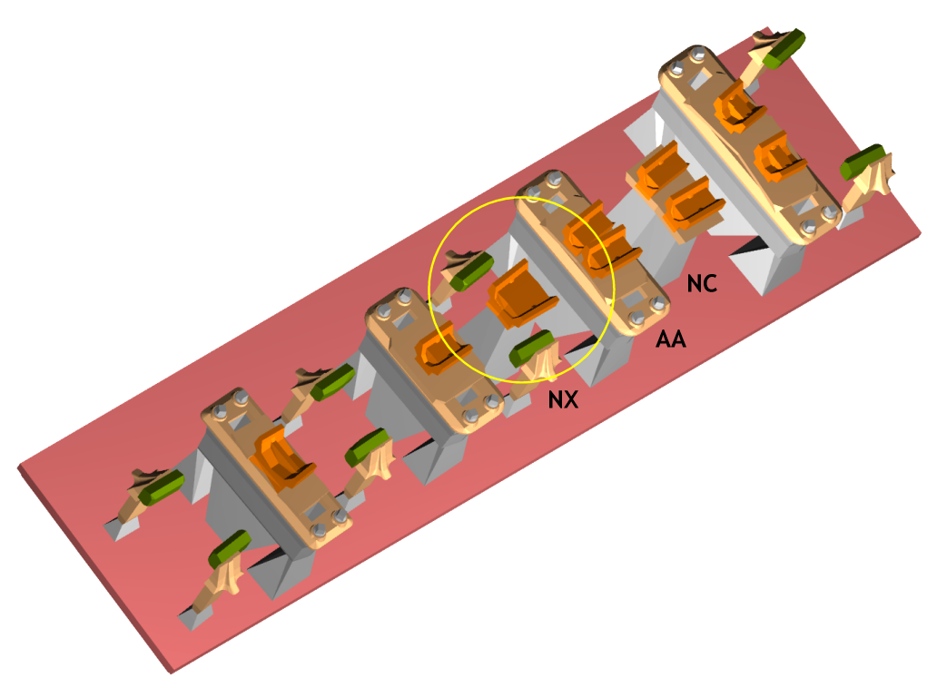
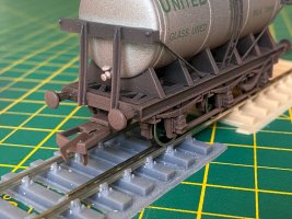
I think we may be over-thinking the need for adhesive/solder. The chair is quite firm in holding the vee nose down level and in correct alignment. The only need is to prevent the rail from sliding out of position. That doesn't have to be done at the nose, it can be done at any of the other chairs -- with some superglue on the loose jaws for example.

For those who prefer to build on the bench and are able to access the underside of the track after assembly, there are several sealing and securing methods which might be used. For example I have previously mentioned using old Humbrol enamel paint as an effective long-term sealant between the plugs and FDM sockets. Or any other old enamel paint from the back of the shed -- I doubt modern water-based paints will work the same way.

But for those who prefer to build track in situ on the baseboard, it's not so easy. I suspect that mostly means users of plywood timbers. Whatever, after junking any idea of using epoxy putty, next time I shall probably put a tiny spot of Humbrol enamel in the AA chair before inserting the rail. You can't get any slower-setting than that -- it needs to be left at least a fortnight to see if it has worked. :) So it's easily removed, wiped off and start again if you are not happy with it.

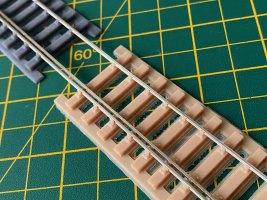
This is the raft of chairs in the STL, for a 1:5 LH crossing in EM/00-SF. The gap is because of the missing BB chair (not yet done):

aa_chair8.png


It's rather wasteful of resin because it is simply a straight export from the templates without any bunching or bulk printing. For each chair I added the matching loose jaws alongside it by shifting the template by one timber-width and changing the chair settings:

aa_chair9.png


If you don't mind wasting resin it is a quick and easy way to do it, and has the great advantage that the chairs are laid out in their proper order with their required loose jaws. Which avoids any confusion or the need for much labelling other than a note on the back of the raft as to which template they are for.

I managed to get 6 of them on the Mars build plate:

aa_chair6.png


It could possibly have been 7, but it's important not to get the rafts too close together to avoid excessive suction against the FEP film. In the real world you would have chairs from several different templates of course.

The above printed fine with no loose bits left in the tank:

aa_chair7.jpg


The slicer said the total cost of the resin was 30p. So that's 5p for a full set of chairs for a 1:5 crossing. Maybe there's not much to be gained by trying to save resin by bunching more chairs into the available space, with the potential confusion about which is which. For the above method it's easy to identify them -- just place the raft on the printed paper template. It's still more economical than some 3D printing projects I have seen where the actual part is supported by a huge resin structure which is all scrap.

It's important when washing these chairs for loose jaws to plunge the build plate up and down in the washer tub a few times, rather than simply relying on the rotary machine swirl. Plunging forces the wash through the tiny slots for the loose jaw pins. When I forgot to do the plunging I found several slots clogged with some hardened surplus resin which had failed to wash out even after several minutes in the washer. The slots are tiny and deep, so a bit of a challenge for the washer alone.

At first sight one way to save resin would be to user shorter support pyramids under the chairs. But there is a reason they are that size -- we need to get the blue cutters round them to remove the chairs from the raft. That's also the reason for not having more than 2 rows of chairs on a raft:

aa_chair9.jpg


aa_chair8.jpg


I wanted to check that these larger chairs can be removed easily with the existing pyramid top sizes. It's important to make a clean cut to avoid any roughness remaining on the plug bottoming in the sockets. But it cut fine. These are the standard Chinese blue cutters which are supplied with the printers. I have several pairs now. :)

The loose jaws don't need cutters -- they can be broken off the raft in the fingers or pulled off the raft using the special tweezers.

cheers,

Martin.
 

Attachments

  • first_test_xing_chairs_1in5_lh_em00sf_c_and_l_rail_fixed.stl
    9.4 MB · Views: 58
_______________
message ref: 6971
Changing the subject, we're expecting an announcement later today from the Scalefour Society about the Finetrax kits for P4. I'm interested to know how well Wayne has held the tolerances for P4.

cheers,

Martin.
Hi Martin.
I will let you know as I am due to receive a review sample next week.
I saw one made up at the DEMU showcase last weekend and first impressions were favourable.
Regards
Tony.
 
_______________
message ref: 6975
@Phil G

p.s. Phil,

I forgot to mention in the file name for that STL -- it is for a regular V-crossing.

The nose chairs change fractionally for a curviform or generic crossing (and some of the other chairs change more than fractionally, e.g the EF chair).

This is why it will be important to keep track of which chairs are for which template, and not assume 1:5 crossing chairs say, can be used for any 1:5 crossing.

But see also this timbering option (which is not the default):

curvi_timbering1.png


More about this:

https://85a.uk/templot/archive/topics/topic_3068.php

cheers,

Martin.
 
_______________
message ref: 6979
.
Here's an issue I could see coming:

socket_breakout.png


This is a 1:4 turnout with square-on timbering. The length of the AB chair means the socket will not be fully contained within the timber, and won't get printed. The BB chair will be even longer and conflict likewise at 1:5.

There are two possible solutions:

Use a wider 14" timber.

Use equalized timbering.

1:4 turnouts tend to be found in old yards and sidings. I very much doubt that an expensive long 14" timber would be found in such a location.

I suspect that the vast majority of 1:4 turnouts are on equalized timbering, which is my preferred timbering layout anyway. For a long time it was the default in Templot. But there was constant complaint that it was not prototypical for some reason, so I changed it -- which I still often regret.

Whatever, it means that selecting the experimental chairing for crossings shorter than 1:6 will be forcing equalized timbering. Just mentioning it now so that it doesn't come as a shock, or result in a flurry of bug reports. :)

cheers,

Martin.
 
_______________
message ref: 6980
.
Now the AB splice chair.

This is normally needed only in crossings flatter than 1:10. Unless the parallel wing option is selected -- as here (this is 1:7):

ab_chair.png


I have marked the splice with a blue line. It would be possible to put some epoxy in there if desired, or some SMT solder paste which can be flashed with a soldering iron after assembly. The resin chairs will resist soldering temperatures if you are quick.

There will be some loose spacer blocks to fill the big empty spaces. They should become captive when the wing rails are added after the vee:

nx_spacer.png


Plus some bolts and fish-washers to stick on the outside of the rails. Eventually. :)

cheers,

Martin.
 
_______________
message ref: 6981
How about using either Loctite

On the other hand would it be possible to solder the joint in situ using low melt solder ? as we solder dropper wires so a quick dab with a soldering iron could be the solution
 
_______________
message ref: 6982
How about using either Loctite

On the other hand would it be possible to solder the joint in situ using low melt solder ? as we solder dropper wires so a quick dab with a soldering iron could be the solution
@Hayfield

Hi John,

The resin I'm using for the chairs (Elegoo ABS-Like resin) is not significantly affected by normal soldering temperatures. I have tested it with my soldering iron set at 250degC, i.e. typical for use with 60/40 electrical solder. For a normal quick clean joint there is no obvious effect. After several seconds it tends to soften and distort a bit, but it doesn't actually melt.

If soldering the rail splice my preferred solder would be SMT paste (solder cream). It can be applied in the splice while assembling and flashed with the iron when finally ready.

Normal lead-free version (217 degC):

https://uk.rs-online.com/web/p/solder-pastes/1466196

A low-temperature version (138 degC):

https://uk.rs-online.com/web/p/solder-pastes/1466202

They are expensive, and you need very little. But could be shared among friends. The smaller syringes are less expensive but often dry solid in the syringe. A tub can be stirred if it is getting dry.

However I'm not convinced the splice needs soldering. Every modeller has their preferred way of doing things, but one of my reasons for creating plug track is so that assembly can be leisurely -- I want to be able to assemble / disassemble parts without rush until I'm happy it's all correct, and only then if strictly necessary apply some slow-setting sealant. Which can be put to one side and left to do its thing. Having discovered how effective old Humbrol enamel paint can be for that if left long enough I'm minded to make more use of it as a sealant. And it's effectively free, after being at the back of the cupboard for 25 years. :)

But I do have a large reel of very thin 22swg cored 60/40 solder. A bit of that could be flattened and placed in the rail web inside the splice, and then flashed with some phosphoric flux when ready.

But once soldered or sealed, there is no way of removing the rails without scrapping the chairs. Of course if printing your own you can easily make some more. But with the loose jaws as intended, any rail can be removed and replaced just by removing the loose jaws -- just like the prototype. I'm not sure how ultra-strong model track needs to be once fixed on a layout, there are plenty of more fragile items on most layouts.

The prototype has bolted spacer blocks through the splice area:

REA:

index.php


GWR:

2_121258_410000000.jpg


which I intend to 3D-print as separate loose inserts which can be inserted when fixing the wing rails in place -- which would help to keep everything solid. Also dummy bolts and fish-washers to be glued on the outside.

My real worry about soldering is not for the chairs, but the PLA timbering base. That is very fluid at soldering temperatures, and any nearby lesser heat would likely soften it to loosen the grip on the press-fit chairs -- possibly upsetting the rail alignments and gauging.

For dropper wires, the intention is that they (or some etched? connector tag thingies) are soldered to the underside of the rail before assembly. And then bent at 90degs to run between the timbers. With a 3mm timber thickness there is space for all manner of such gubbins to be lost under the ballast. With the loose jaws the rail is dropped in vertically, the chairs don't need to slide along it.

As I've mentioned there are lots of ideas to try (and mostly discard :) ) once I've got enough parts made that we can start actual track building with plug track.

cheers,

Martin.
 
_______________
message ref: 6983
Hi Martin,
I fully understand your perspective on trying not to use a conventional glue of any kind on the splice, Acknowledging your old paint is very close to a slow hardening adessive and may work out perfectly. My concern would be movement overtime once the turnout has been in traffic for a bit, will there be a tendency for the splice to start to open? I don't know maybe not.

I just can't help thinking the prototype bolted the splice together for a reason. Whilst I know model weights are nothing like the weights the real thing sees, its still possible in model traffic the splice will move.
That's the sole reason I am keen to try and find a good safe way to fix the rails, I very much like your solder paste Idea however. maybe even your old paint trick will do the job. Or apply Cyno to the side of the splice when adding the dummy bolts!!
One great thing about plug track is all the options and permutations it allows for.
Phil,
 
_______________
message ref: 6984
@Phil G

Hi Phil,

If the two spacer blocks were linked across below the rails in some way, that would in effect lock the splice solid.

It's difficult to imagine what forces on a model railway might push the splice apart. But if it did happen, and you haven't glued anything, you can easily remove the rails and replace/repair them.

The most likely issue would be if they were to slide back out of position. That might be preventable by doing something with the dropper connection, such as soldering it to a brass screw or pin between the timbers. All disappears below the ballast.

cheers,

Martin.
 
_______________
message ref: 6985
@Steve_Cornford

Hi Steve,

You kindly offered to make some test prints.

I wondered if you or other 00-SF modellers have yet made any check rail chairs, and have some modern 00 RTR stock you can try through them?

I'm mainly interested to know if the flange depth clears ok?

I don't have any 00 RTR models here to try, and I don't want to find out too late that this or that model clonks on the plug track chairs. I think I have left enough depth, and it was one of the things I had in mind at the design stage, but it would be reassuring to know that everything clears ok in practice.

Thanks.

cheers,

Martin.
 
_______________
message ref: 6987
Will do, but am away in New Forest for a couple of days.
is track curvature relevant?
Do you have a particular template tou wish me to test?
Steve
@Steve_Cornford

Thanks Steve, no rush.

It's not track geometry or radius or back to backs etc. What I'm interested to test is the flange depth. Do the flanges hit on the chairs? I can't test it myself because I don't have any 00 RTR wheels here. Well, not since 3-rail days -- I'm not trying to cater for those. :)

cheers,

Martin.
 
_______________
message ref: 6989
@AndyB

Hi Andy,

On which turnouts?

Parallel-wing crossings are sometimes seen in crossovers, where the wing rail on one V-crossing continues to become the check rail on the other V-crossing. The actual criteria for deciding to install a parallel-wing crossover has never been very clear to me, but I think it is related to the presence of an adverse cant across the running lines.

2 sets of parallel wings here (sorry about the poor quality):

1870_031520_550000000.jpg


One unsolved mystery is how the 1:20 inclined wing rail merges into a vertical check rail, there must be a twist somewhere along it -- but where? It's not a problem for plug track, because all rails are vertical.

cheers,

Martin.
 
_______________
message ref: 6992
Martin,

If it doesn't add further confusion it might shed a little light on the unsolved mystery.

Screenshot (53).png


Screenshot (54).png
Screenshot (55).png


The second note talks about "gradually canted" but what I don't understand is on the diagram, what I would call a wing rail they call a check rail and what I would call a running rail they call a wing rail. I'm confused :)

Andy.
 
_______________
message ref: 6994
@Steve_Cornford

Hi Steve,

You kindly offered to make some test prints.

I wondered if you or other 00-SF modellers have yet made any check rail chairs, and have some modern 00 RTR stock you can try through them?

I'm mainly interested to know if the flange depth clears ok?

I don't have any 00 RTR models here to try, and I don't want to find out too late that this or that model clonks on the plug track chairs. I think I have left enough depth, and it was one of the things I had in mind at the design stage, but it would be reassuring to know that everything clears ok in practice.

Thanks.

cheers,

Martin.
Hi Martin, I'm more than happy to run off some test prints. just ping/share the stl file and I'll resin print complete or separate timbers & chairs as required. I have many 00 RTR items I can test through the test track as well. Terry
 
_______________
message ref: 6996
Hi Martin,

More on the mystery about the check rail. The LMS had "PW" (parallel wing) common crossing chairs including PW versions of the usual check-rail chairs but the PW versions have the check-rail (wing rail) tilted at 1:20.

The crossover and double junction schematics show PW type chairs under all the parallel wing rails.

Cheers,
Andy
 
_______________
message ref: 6997
Hi Martin, I'm more than happy to run off some test prints. just ping/share the stl file and I'll resin print complete or separate timbers & chairs as required. I have many 00 RTR items I can test through the test track as well. Terry

Thanks Terry.

Here is a short bit of 00-SF one-piece track with a check rail. It's for C&L rail.

test_check_rail_00sf.jpg


I would be grateful if you would run an assortment of 00 RTR vehicles along it, both carefully and roughly, and report if you can hear or feel any clicking or clonking sound as the bottom of the wheel flanges hit the chairs. Thanks.

cheers,

Martin.
 

Attachments

  • test_check_rail_00sf_fixed.stl
    2.9 MB · Views: 55
_______________
message ref: 6998
@Terry Downes

p.s. Terry,

Sorry I left that at full 3.2mm timber depth. It didn't need to be for a test piece and it's a bit wasteful of resin.

cheers,

Martin.
 
_______________
message ref: 6999
Martin,

Quick question...and I appreciate that this is evolving and that you are working on other priorities. If I joggle my stock rails will this be picked up in the STLs or this is something for the future?....if not I can compensate manually by adjusting the first couple of slidding chairs after the joggle over a fraction but dont want to miss the opportunity if the feature is already enabled.
 
_______________
message ref: 7000
I just can't help thinking the prototype bolted the splice together for a reason. Whilst I know model weights are nothing like the weights the real thing sees, its still possible in model traffic the splice will move.
@Phil G

Hi Phil,

We have a new component. I have called it a nose clamp (NC):

nose_unifier3.png


nose_unifier2.png


nose_clamp.png


nose_clamp1.png


It serves two purposes:

Visually it looks like the spacer blocks. When the cosmetic bolt heads and fish-washers have been applied to the rails I think it will look quite convincing.

Functionally it serves to lock the splice together. Initially while inserting the point and splice rails, it is placed close to the AA chair and supported at rail level by some temporary means (Blu-Tack). It then slides back towards the B chair, until the splice is wedged firmly into it. At which point it should be mid-way between the chairs. The wing rails can then be added to lock it in place.

The non-prototype under-plate is recessed from the rail edge, and will be difficult to see after ballasting.

It will need some accurate filing using the jigs to allow everything to fit.

This is all still theoretical of course, and may collapse in flames when I have made some test prints. :)

cheers,

Martin.
 
_______________
message ref: 7001
Martin,

Quick question...and I appreciate that this is evolving and that you are working on other priorities. If I joggle my stock rails will this be picked up in the STLs or this is something for the future?....if not I can compensate manually by adjusting the first couple of slidding chairs after the joggle over a fraction but dont want to miss the opportunity if the feature is already enabled.
@Michael Woods

Hi Michael,

Straightcut/joggled switches are not currently supported for the REA switches. That will come when I do the GWR chairs.

REA switches were sometimes joggled when used in heavy-traffic facing locations. It's fairly easy to replicate them with the existing chairing by splitting out the stock rails on separate partial templates. I can explain that in a video if you wish -- which size of switch are you looking for?

But it's very difficult to model a joggled switch accurately to scale, and almost impossible to see from normal viewing distance. The joggle depth is 3/8" which scales to less than 5 thou in 4mm/ft scale. I often see model switches with much exaggerated joggles, and they look a bit silly. Most modellers settle for a simplified model version of undercut switches, which are much easier to build and look good.

cheers,

Martin.
 
_______________
message ref: 7002
Thanks Martin.

I was referring to the turnouts steeper than 1:10. I didn't realize the AB chair was ever optional. It looks like the LMS always included it.

Cheers!
Andy
@AndyB

Hi Andy,

Some confusion here.

There is no such thing as a prototype AB chair. I have changed some of the chair designations for Templot because we have to accommodate:

wider than prototype model flangeways for 00/EM etc.

adjustable crossing angles

adjustable check end flare lengths and angles

adjustable chair/timber spacings

On the prototype the reach part of the wing rail (the part alongside the vee nose) spans 2 chairs up to 1:10 (called A and B), and 3 chairs for flatter angles (called A, B and C).

For Templot I have changed that to AA and BB, or AA, AB and BB.

In the case of parallel-wing crossings it becomes AA AB, or AA, AB, AB.

I will explain it all in greater detail when I have finally got something usable finished and can show illustrations.

Wing rails are inclined at 1:20 (on the prototype) and wheels run along all or part of them. Check rails are vertical and wheels do not run along them.

Thanks for the drawings. I do have copies of those and have seen the notes about the twists in point rails, for both V-crossings and K-crossings. That info is generally available.

What is difficult/impossible to find is information about twists in check rails. Drawings for parallel-wing crossing chairs show the wing rail inclined. The CC check rail chairs have vertical check rails. It follows that if a rail is continuous through both it must have a twist in it somewhere. It needs to be twisted about an axis along the rail head, so that the flangeway gap remains constant. My guess is that the twist is achieved by means of special fishplates, for easier maintenance. But I have never found any evidence to support that idea.

But it is all academic for plug track, which has vertical rails throughout. :)

cheers,

Martin.
 
_______________
message ref: 7003
Martin,

There may be enough flex in the rail between chairs that well fitted keys will make the adjustments required. It may be that you would key up to the last inclined chair, miss out a few chairs on the check and then work back to the 1st vertical chair. I have done that with recalcitrant rail on more than one occasion, where several good wacks with a keying hammer has failed to sort it out.
 
_______________
message ref: 7004
@Terry Downes

p.s. Terry,

Sorry I left that at full 3.2mm timber depth. It didn't need to be for a test piece and it's a bit wasteful of resin.

cheers,

Martin.
Hi Martin, All printed & all excellent, no bumping/clashing with or without weights/force being applied downwards. Here are a couple of photos. This was a new Dapol 00 tanker but, I will continue to try with as many different wheels/manufacturers as I can lay my hands on. Please let me know if You want/need anymore info/feedback.
 

Attachments

  • IMG_4816.jpg
    IMG_4816.jpg
    818 KB · Views: 66
  • IMG_4818.jpg
    IMG_4818.jpg
    731.1 KB · Views: 66
  • IMG_4819.jpg
    IMG_4819.jpg
    786.5 KB · Views: 66
  • IMG_4821.jpg
    IMG_4821.jpg
    864.3 KB · Views: 63
_______________
message ref: 7005
Thanks Martin! Got the picture now.

I suppose if the chair only supports one rail the "gradual canting" could be made with sloped recesses in the timbers. Of course that won't work for check chairs. Special fish-plates do seem a likely solution in that situation.

Cheers,
Andy
 
_______________
message ref: 7007
@Phil G

Hi Phil,

We have a new component. I have called it a nose clamp (NC):

View attachment 6139

View attachment 6140

View attachment 6154

View attachment 6156

It serves two purposes:

Visually it looks like the spacer blocks. When the cosmetic bolt heads and fish-washers have been applied to the rails I think it will look quite convincing.

Functionally it serves to lock the splice together. Initially while inserting the point and splice rails, it is placed close to the AA chair and supported at rail level by some temporary means (Blu-Tack). It then slides back towards the B chair, until the splice is wedged firmly into it. At which point it should be mid-way between the chairs. The wing rails can then be added to lock it in place.

The non-prototype under-plate is recessed from the rail edge, and will be difficult to see after ballasting.

It will need some accurate filing using the jigs to allow everything to fit.

This is all still theoretical of course, and may collapse in flames when I have made some test prints. :)

cheers,

Martin.

Hi Martin,

What a brilliant idea, accessing the underside of the rail Vee joint. Although nose clamp sounds like something a synchronised swimmer would use :) How about Vee plate clamp or VPC, anyway whatever you call it, its still genius idea.

Phil,
 
_______________
message ref: 7009
Hi Martin, All printed & all excellent, no bumping/clashing with or without weights/force being applied downwards. Here are a couple of photos. This was a new Dapol 00 tanker but, I will continue to try with as many different wheels/manufacturers as I can lay my hands on. Please let me know if You want/need anymore info/feedback.
@Terry Downes

Many thanks Terry. (y) That's very reassuring. If you could repeat that at some time with assorted current products of Hornby, Bachmann, etc., we would be pre-armed for when someone inevitably reports that model X from 1963 doesn't run on plug track. :)

Likewise anyone else who wants to print the STL and has access to 00 RTR models. Thanks.

cheers,

Martin.
 
_______________
message ref: 7011
@Phil G

It's very desirable that the NC nose clamp thingy is printed in its final position between the chairs on the raft, to avoid confusion about where it belongs and on which template, and so that if desired the rail alignments can be tried through the chairs while still on the raft.

But that means some care will be needed in positioning the second template containing the loose jaws, to avoid conflicts with the clamp:

nose_clamp2.png


I suggest moving the second template in the trailing direction, i.e. moving the B jaws back towards AA, rather than moving the AA jaws forwards towards B. At most crossing angles this should leave plenty of fresh air around the NC clamp -- the above is 1:8.

I will look at providing a button to do the required template shift automatically.

Even so, the clamp will be needed for construction before the B jaws, so will need to be removed from the raft sooner. That won't be easily possible with the B jaws in the way, so it will be necessary to remove at least one of them first. They will need to be put carefully to one side until needed, and not muddled up which one is which.

All these jaws are slightly different, and the best way of not getting them in a muddle is to leave them on the raft until needed. At first sight several of them might look interchangeable, and so they might be as far as fitting the rail is concerned. But if you use the wrong one it is very likely that the jaw rib will not fit neatly between the chairs screws, and might prevent the jaw being pushed fully home.

All this stuff is going to be needed for the plug track instructions. I'm writing it now so that if I forget to mention it ever again it is at least written down somewhere.

cheers,

Martin.
 
_______________
message ref: 7012
Or shift the jaws of chair AA (and the jaws of chairs to the left of chair AA) to the left, and jaws of chair AB/BB ( and jaws of chairs to right of chair AB/BB) to the right, thus leaving the NC component on it's own & accessible.
Well done for the NC solution, especially the co dept of t DDT dial fittingbif point & splice rail whilst chairs still on raft.
Steve
 
_______________
message ref: 7014
Hi Martin,
I can't help but think the raft is the perfect build platform for the vee of a crossing or even taking further and once you get round to it the K crossing as well.
I just did a very rough check and at 1 in 12 assuming we printed from AA to FF chairs the raft would be approx. 65 mm long and 15 mm wide if all these chairs and NC + anything extra you felt would benefit construction, or even cosmetic bits, were printed at in one go on the same raft, not only would you have them in the right place and easy to identify. You could quite literally slide both sided of the pre sliced vee rails right down the chairs still on the raft.
if you expand the idea just a little bit, and here I don't know how hard this would be to program. you could have something like a shift vee chairs to print function.
IE the turnout would be made in the normal Templot way and once happy with what you wanted you would Do experimental chairing
and then presumably on the DXF/STL page there is a shift chairs to print option. which would position the chairs on a raft in the correct spacing.
I guess the down side is not optimising space on the build plate, the upside would basically be a ready made Vee kit, complete with assembly jig.
It may need a sight rethink on the Xuron cutter spacing, but I for one would rather cut a preassembled Vee off the raft with say a junior hacksaw for example, then have to print cut and then assemble a vee crossing. The advantage is it opens up more options for spacing the loose jaws and anything else such a dummy bolts and plates.
I have no idea how practical that would be for programming however. and I am not suggesting you rush into this its just food for thought
hope you get what I thinking here. Please also let me know if I am dreaming :)
phil
 
_______________
message ref: 7017
Hi Martin,
I forgot to mention the NC would be on the raft with a weak build pillar, designed to push back a bit a wee bit quite easily. Once your ready the NC pushes back to the AB or BB chairs a fraction and thus locks the rails in place ready to cut the vee free for the raft. the completer vee would then just be a push down fit into the timber holes.
cheers
phil,
 
_______________
message ref: 7018
@Phil G

Hi Phil,

I'm not clear what you are suggesting which can't be done now? If you just export the chairs for a template they will all be in the correct relative positions. You just draw a raft rectangle under them. I'm intending to automate that raft rectangle drawing in due course.

You can then build the entire crossing on the raft if you want to. But you would need to be quite quick after printing, because every raft I have ever printed has curled after a day or two. I did however find that immediately sticking it down with strong double-sided tape to a piece of board prevented curling.

The assembled crossing with chairs would need to be removed from the raft with a junior hacksaw or similar -- using the cutters would distort it. Presumably the chairs would be locked to the rails with superglue or some such?

The NC can be cut free before you start and locked into position as you add the wing rails.

All this is fine for single turnouts. It is going to need some thinking for complex formations such as the crossings in an outside slip. On balance I think building a crossing with the chairs fixed in the timbers first would be easier than transferring a chaired crossing afterwards, i.e. plug track as originally intended. But each to his own. I'm building as many options into the process as I think folks might want. :)

cheers,

Martin.
 
_______________
message ref: 7019
@Phil G

Hi Phil,

I'm not clear what you are suggesting which can't be done now? If you just export the chairs for a template they will all be in the correct relative positions. You just draw a raft rectangle under them. I'm intending to automate that raft rectangle drawing in due course.

You can then build the entire crossing on the raft if you want to. But you would need to be quite quick after printing, because every raft I have ever printed has curled after a day or two. I did however find that immediately sticking it down with strong double-sided tape to a piece of board prevented curling.

The assembled crossing with chairs would need to be removed from the raft with a junior hacksaw or similar -- using the cutters would distort it. Presumably the chairs would be locked to the rails with superglue or some such?

The NC can be cut free before you start and locked into position as you add the wing rails.

All this is fine for single turnouts. It is going to need some thinking for complex formations such as the crossings in an outside slip. On balance I think building a crossing with the chairs fixed in the timbers first would be easier than transferring a chaired crossing afterwards, i.e. plug track as originally intended. But each to his own. I'm building as many options into the process as I think folks might want. :)

cheers,

Martin.
Hi Martin,
I understand what I am thinking of can basically be done as part of a making your own raft, which is what has to happen anyway,
My thoughts were if the pillar for the NC was lets say very similar to the loose jaw pillars but say four of them in each corner of the NC maybe only two are required? I am not sure.
That would allow for correct positioning of the NC in relation to the Aa, Ab/Bb chairs, then all you do is put two finger nails or tweezers on the side of the NC and push it back slightly towards the Ab/Bb chair the angle would naturally create a locking wedge action. As you say the Aa chair if prebuilt may just need a drop of super glue to hold it in place all the others would basically be captured on the bottom rail profile. It maybe better to leave the Aa chair loose and assemble this and the rest of the vee at the same time.
Please note I am only talking about prebuilding the Vee or K or more complex rails this way, I am not suggesting adding any wing rails at this point, simply having a vee with all the chairs that bridge the vee pre built onto the vee, These can still float up or down the vee rails its just there pre loaded with ease. This sub assembly is then inserted into the timbers in exactly the same way a singularly printed chair must be inserted into the timbers before rails are added. In this case the wing rails are then added next and held down by the loose jaw option.
Your point about the raft bending is a good point. That would need to be considered as it would effectively prevent batch making vee assemblies and would mean, its a print vee chairs, add vee rails and release from raft exercise, unless a method of preventing raft bending can be worked out.
What I would agree with is, once all the chairs are readily folks can find there own best solutions to how to build up the turnout.
So a print vee rail chairs option maybe totally unnecessary and a total waste of your time.
Phil
 
_______________
message ref: 7020
Hi Phil,
A bit of feedback from experience of assembling rail directly onto chair rafts.
I tried this with plain track using a raft of S1 chairs.
Having inserted the rail into the chairs on the raft the problem comes when searching the chairs with rail affixed from the raft.
Using the "Xuron" cutters the force exerted as you cut each chair eventually results in broken jaws on a chair.
So I tried sawing which was a lot better but I still managed to break the odd chair.

It was much more successful to just cut the chairs slide them onto the rail and plug result into the timber base.

As far as the NC goes I think Martin mentioned that the addition of the wing rails locks it into place.
The NC is a very small component, as are the loose jaws.
Martin has developed a useful set of tweezers grips to aid with the handling of the jaws, maybe an NC version might follow?
I think the main use of the raft of chairs is the trial fitting and settling of the point and splice rails, as one would be able to view the join from more angles.
 
_______________
message ref: 7021
Loose jaw slots.
After initial "dirty" wash, I use a drinking straw to direct a blast of air through the slots to help clear any residual resin, but take care not to breath in any IPA fumes.
A can of compressed air would be better I suppose.
 
_______________
message ref: 7022
Hi Phil,
A bit of feedback from experience of assembling rail directly onto chair rafts.
I tried this with plain track using a raft of S1 chairs.
Having inserted the rail into the chairs on the raft the problem comes when searching the chairs with rail affixed from the raft.
Using the "Xuron" cutters the force exerted as you cut each chair eventually results in broken jaws on a chair.
So I tried sawing which was a lot better but I still managed to break the odd chair.

It was much more successful to just cut the chairs slide them onto the rail and plug result into the timber base.

As far as the NC goes I think Martin mentioned that the addition of the wing rails locks it into place.
The NC is a very small component, as are the loose jaws.
Martin has developed a useful set of tweezers grips to aid with the handling of the jaws, maybe an NC version might follow?
I think the main use of the raft of chairs is the trial fitting and settling of the point and splice rails, as one would be able to view the join from more angles.
Hi Steve,
I totally agree with you, I too have done the same thing, xuron cutters apply too much axial movement when cutting, junior hacksaw blade was better, but a Dremel with a slitting wheel did the job fine. What I found very easy though was sliding a rail down the raft.
Was that your observation?
As to your comment about the NC being very small, that's exactly my point, the less handling the less looking for the thing when it gets dropped!! you also touched on the other thing I was thinking about, IE if you can easily view to access, then it makes sense to me at least to add any dummy fittings at this stage.
All said and done I guess we will all find our preferred way to do this, and I am not saying my thoughts will even last with me, but right now I still see some logic to it.
This is not about changing Martin's process, there is nothing wrong with that at all. Its about looking if other options would compliment the process.
cheers
Phil
 
_______________
message ref: 7023
Back
Top