Templot Club forums powered for Martin Wynne by XenForo :

TEMPLOT 3D PLUG TRACK - To get up to speed with this experimental project click here.   To watch an introductory video click here.   See the User Guide at Bexhill West.

  • The Plug Track functions are experimental and still being developed. Some of the earlier pages of this topic are now out-of-date.

    For an updated overview of this project see this topic.   For some practical modelling aspects of using Plug Track see Building 3D Track.

    The assumption is that you have your own machines on which to experiment, or helpful friends with machines. Please do not send Templot files to commercial laser cutting or 3D printing firms while this project is still experimental, because the results are unpredictable and possibly wasteful.

    Some pages of this and other topics include contributions from members who are creating and posting their own CAD designs for 3D printing and laser-cutting. Do not confuse them with Templot's own exported CAD files. All files derived from Templot are © Martin Wynne.
  • The Plug Track functions are experimental and still being developed.

    For an updated overview of this project see this topic.   For some practical modelling aspects of using Plug Track see Building 3D Track.

    The assumption is that you have your own machines on which to experiment, or helpful friends with machines. Please do not send Templot files to commercial laser cutting or 3D printing firms while this project is still experimental, because the results are unpredictable and possibly wasteful.

    Some pages of this and other topics include contributions from members who are creating and posting their own CAD designs for 3D printing and laser-cutting. Do not confuse them with Templot's own exported CAD files. All files derived from Templot are © Martin Wynne.

Experimental 3D plug track - up to version 244c

Quick reply >
Wthin Templot the text characters are limited to:-
the numbers: 0,1,2,3,4,5,6,7,8,9
the letters: A,C,E,F,G,H,L,P,U
the characters: minus,equals,underscore
the # character gets translated to minus
all other characters get translated to the "unknown" character which is three horizontal bars of segments (of the 7 segment display paradigm)

View attachment 6446
Here is a 4mm L1 fixed jaw chair raft with a text label #4#L1#F to identify it. This has an exagerated text height of 5mm.
I suppose I should have put 75CL in their to represent suitable for code 75 C&L rail.
Steve on a rainy day
@Steve_Cornford

Hi Steve,

In the next update I have added lower case:

c d h i n o r t u

Also full stop/decimal dot and spaces.

Also O is the same as 0, I is the same as 1, comma is the same as full stop.

Pipe ( | shift+backslash ) is the same as 1 but on the left instead of right.

They are not very readable in 7-seg and one fine day I will increase them to 16-seg.

The decimal dot is exaggerated, because otherwise Cura ignores it as a blip in the design:

jig_data.png


p.s. the 3 horizontal bars character is called a hamburger. :)

cheers,

Martin.
 
_______________
message ref: 7299
Hi Martin,
Enhancement requests (to be added to the end of your todo list if approved by you)
Colour selection
When we display the box list it displays the optional colour of each background template as in a column just before the templaye ID number:-
1690817031924.png

Some of these colour differences are quite subtle, especially if like me you have chosen a lot!
Would it be possible to display the RGB code of the relevant colour when you click on the [info] button?
Or would it be possible to click on the colour swatch if a particular template in the list & get Templot to copy that colour to the "experimental 3D" pop-up window, thus enabling the next template to be stored to be set to the same colour combo?

Of course now that I have learnt about "group" selection & export of "by group" this might be redundant..


Background shapes - Raft/Slabs
It is possible to attribute colours to these rafts, thus differentiating between them.
But if we have say 3 rafts each with a different coulur, but each colour matching a set of stored templates, when we generate a 3D export "by colour", having chosen a colour, all the rafts get included in the export, including ones without colur and ones with the wrong colour. Would it be possible to make the export "by colour" just export the chosen colour raft in much the same way that it only exports the chosen colour backgound templates?
I dont think that their is a group option for shapes.

Steve
 
_______________
message ref: 7300
Hi Martin,
Enhancement requests (to be added to the end of your todo list if approved by you)
Colour selection
When we display the box list it displays the optional colour of each background template as in a column just before the templaye ID number:-
View attachment 6450
Some of these colour differences are quite subtle, especially if like me you have chosen a lot!
Would it be possible to display the RGB code of the relevant colour when you click on the [info] button?
Or would it be possible to click on the colour swatch if a particular template in the list & get Templot to copy that colour to the "experimental 3D" pop-up window, thus enabling the next template to be stored to be set to the same colour combo?

Of course now that I have learnt about "group" selection & export of "by group" this might be redundant..


Background shapes - Raft/Slabs
It is possible to attribute colours to these rafts, thus differentiating between them.
But if we have say 3 rafts each with a different coulur, but each colour matching a set of stored templates, when we generate a 3D export "by colour", having chosen a colour, all the rafts get included in the export, including ones without colur and ones with the wrong colour. Would it be possible to make the export "by colour" just export the chosen colour raft in much the same way that it only exports the chosen colour backgound templates?
I dont think that their is a group option for shapes.

Steve
@Steve_Cornford

Hi Steve,

Many thanks for your ideas. It's all doable, but quite a lot to think about. :)

Clicking on a colour patch separately from clicking to select the template in the list is doable but tricky.

The storage box dialog is currently packed solid with not much space for extra features or buttons. The obvious solution is to make it bigger, but I know that not everyone has a large screen. How much of your screen does it take up? Is there space to make it about 40 pixels deeper, for an additional row of information and buttons? On the other hand it has its own menu structure, and the easiest solution is always to add extra menu items. But it's difficult to display colours on the menus without creating a lot of work elsewhere.

The rafts being in the background shapes is just a temporary kludge so that we can at least get some chairs printed, it's not intended to be the final design. There will be a separate function to draw rafts around the chairs, and hopefully a function to create rafts automatically for all the chairs in the export.

In the meantime, if you have several rafts, you can prevent unwanted ones being exported if you select it in the list and untick the box below the list:

shapes_tickboxes.png


As far as I know that's working for raft exports, you might like to test it for me. If not it's a bug, and an easy fix.

p.s. If you click the other box, you can flash it on and off on the trackpad to make sure you have selected the right one.

You can change the colour of brick shapes in the splint/slab menu on there.

Thanks again,

cheers,

Martin.
 
_______________
message ref: 7301
Hi Martin,
Unticking the "show on output" works fine, well at least in the preview (my favourite button).
That solves the problem of having multiple raft/slabs as shapes & only wanting one to be exported, thanks :)

Here is she storage box screen extended down to fit my laptop screen, I have program size set to "small"
1690824814230.png

Sorry here is some more feedback, hope it helps not hinders.
By the way in an earlier post you mentioned the "save custome date" and "load custom data" on the Export DXF/STL dialogue screen.
I do use those and found them very useful.
It would be good if it saved any changes made by pressing buttons in that same column that the save/load buttons are.
At the moment it does not save the [chair/socket fit] button data nor the [chair support] data
I tend to reduce this parameter from 0.79mm (the default) to 0.60mm to give a mre defined edge to slide the huron cutters up to before snipping the chairs, without any adverse print problems.
Cheers Steve
edit to add missing screenshot, whoops
1690826026469.png
 
_______________
message ref: 7302
Last edited:
@Steve_Cornford

Hi Steve,

Yes of course. Every single thing will be in the save custom files, including whether or not you want sugar in your coffee while waiting for the print to finish. :)

It's just that I haven't got round to doing it all yet. Writing the save and load functions is very tedious because it's in XML format. It's also very easy to make mistakes which the compiler won't flag, so I have to be very careful and do a bit at a time.

Also there will need to be some files to save the custom chair designs when we get that far, and the chair heaving settings.

So much still to do. :(

I'm just now finalising the designs for the filing jigs for the vee rails. Next will be the jigs for the switch blade planing. Then some rail bending fixtures for the knuckle bends and switch set bends. Then the slab & bracket "A" chair. Then the chairs for K-crossings...

cheers,

Martin.
 
_______________
message ref: 7303
<ah>the joys of XML</ah>
I have had to write exports from accounting software to XML format files in the past. Verbose to say the least, now i cant even remember the name of the very good XML editor/viewer that i used for checking.
But if i can help in any way to reduce the tedium let me know.
Luddite Steve who believes George 4 is the best operating system known to man.
 
_______________
message ref: 7304
@Steve_Cornford @graeme @Alistair Ward

It doesn't have to be XML -- left to myself I would probably have used a binary format (as the BOX files). But we need a format which Graeme and Alistair can one day load into OpenTemplot -- if we ever get as far as chairs and 3D exports in OpenTemplot.

Templot already contained Nils's XML engine (for the sketchboard files), so I used that. It's also used for the BGS3 shapes files.

Thanks for the offer to help, I may take you up on that later. If you open a saved SK4 file in a text editor you can see what is so far in there -- not very much. Note that most of the data is in prototype inches, even for stuff which doesn't have a prototype such as the plugs. If you can remember the utility you used for checking XML that would be great.

cheers,

Martin.
 
_______________
message ref: 7305
.
Vee-rail filing jigs now done.

p.s. it's grey FDM filament, not a resin print:


new_filing_jig.jpg


new_jig5.png


Working fine. Can be printed for any angle 1: 0.5 to 1:20 in 4mm/ft scale.

Overall size for most angles is 85mm x 50mm. The thickness can be set as required -- the default is 18mm.

The large opening in the middle allows it to be clamped on the corner of a table, if holding it in a bench vice isn't convenient.

Using all-threads with double wing nuts makes it easy to hand tighten without needing any other tools ( screwdriver, spanner, socket) on the head, but obviously any ordinary M6 (6mm) bolts will do.

The square holes are slightly undersize -- self-tap the bolt through the hole, then pull it through with a wing nut to strip the thread in the jig. The result is a close fitting bolt which will align the two halves.

Total cost of filament about £1. eSUN toughened PLA Plus, to resist filing -- same as used for the timbering bases:

https://www.amazon.co.uk/gp/product/B07FQ75QG2

Total time to print both halves was 3 hours 45 minutes. If using a glass bed, add 20 minutes or so for it to go cold -- you will hear a crack as differential contraction frees it from the glass and you can then just lift it off. FDM printing always seems slow -- until you start some other job while you are waiting, in which case I can guarantee the print will be finished before you are ready for it. :)

I will write some more later about the slicer settings to use in Cura, and adjustments for 7mm/ft rail.

In the next Templot update. Should I be releasing this now, or wait until I have done the filing jigs for the switch blades? They are more involved and will take a bit longer.

cheers,

Martin.
 
_______________
message ref: 7307
Neat enhancement for clamping to work table.
Perhaps I should refrain from voicing opinion regarding release into the wild as I don't have an FDM printer(yet)! Whatever is mist convenient for you. I think you have mentioned that it would include a few other minor improvements/fixes that you would like exercised.

Fishplates
In the meantime I have been giving these fishplates a go:-
20230801_095446.jpg
Available from Brassmasters or Scalefour stores.
Each pair has a front & back.
I assume the bolt heads go on the inside face of the running rail, and the nuts go on the outside.
In some places I have just cut a not h in the top of the rail coinciding with the rail break in Templot, then super glued the fishplate centred under that cut. I can do this as the rail drops vertically onto the chairs and then loose faws inserted, rather than having to slide chairs along.

I find it is much easier to position & glue these with rail on its side.
Where there are actual physical breaks in the rail I am going to try soldering one of each pair of fishplates to each rail. The starting rail having inside fishplates then subsequent rails having the outside fishplate at that end and an inside fishplate at the other end.
We shall see how I get on, all part of the great experiment.
where I need an insulated fishplate I have managed to use an Exactoscale H fishplate, by gluing it onto the end of the wing rail before dropping vfx the wing rail down onto the chair seats & inserting the loose jaws.
Tge blade/ closure rail can then be slid into the other part if the H as you drop it down onto the chair seats of the loose jawed chairs.
Steve
 
_______________
message ref: 7308
Last edited:
@Steve_Cornford

Hi Steve,

Many thanks for the info re fishplates.

When we have got the plug track properly going we shall need a Plug Track Builders Guide with all this stuff collected in one place. Vertical assembly of the rails does change some of the existing published track building methods.

I am intending eventually to 3D-print some fishplates, to be glued on the rail sides. There will be a tab on the back of each half, to fit between the rail ends, about 10 thou or so thick. The tabs split across diagonally to fit together:

printed_fishplates.png


With the neat square rail ends possible with the loose jaws, and these thin fishplate tabs, it should be possible to create unobtrusive isolation gaps at the rail joints.

But you are well advised not to hold your breath for the above. :) At least from me -- nothing to stop anyone else doing them in CAD and posting the STLs. Anyone?

It may be that we need separate versions for P4 (with full bolt heads), and the rest (with reduced bolt heads to clear wheel flanges). No need to reduce the nuts because they go on the outer side of the rail.

cheers,

Martin.
 
_______________
message ref: 7309
Hi Martin,
Enhancement requests (to be added to the end of your todo list if approved by you)
Colour selection
When we display the box list it displays the optional colour of each background template as in a column just before the templaye ID number:-
1690817031924.png

Some of these colour differences are quite subtle, especially if like me you have chosen a lot!
Would it be possible to display the RGB code of the relevant colour when you click on the [info] button?
@Steve_Cornford

Hi Steve,

Thanks for your comments.(y)

I have moved the brick tickbox down from the side, and increased the height of the storage box by 36 pixels -- to make room for a new panel:

box_bricks1.png


The panel at A-A appears if the template selected in the list is a brick template. The panel shows its marker colour, and 3 buttons.

The first button shows the rgb colour in both decimal and hex. Clicking it allows you to change it to any other colour.

The second button changes it to match the active colour showing at B. The third button allows you to change the colour at B to match this colour. By this means you can copy this colour to other templates in two stages.

I hope this covers all likely requirements, because there isn't room for any more. :) Anything else would have to go in the menus.

Will be in the next update 241b.

For interest here is my design view -- as you can see it's well packed:

box_bricks2.png


For templates which are not brick templates, the new panel won't appear -- leaving some blank space which might be used for something else if a need arises.

cheers,

Martin.
 
_______________
message ref: 7311
Hi Steve,

With regards the fishplates, mostly the nuts are on the outside, but in some situations, it's not possible and the nuts have to go on the inside. One situation that this happens is where there's a check rail, because there's not enough room to get the bolts in, without removing the check rail, first.
 
_______________
message ref: 7314
Martin,

Having taken the plunge with 3D printers (although the FDM one is still in its box!), I've been trying to master the basics of Fusion 360. Fishplates sprang to mind as something that could be fun. My first attempt was to use standard BR designs but realised a hybrid would be needed when reading through the forum about the 'model' rail differences. I opted to use the C&L section (as it was the only one I could see with any dimensional detail!) and included thin joining strip, which can act as insulators if required.

I've tried both types as a loose fit but have yet to try glued in place - that's my excuse if they don't fit! Two files attached, one for non-skirted plates (54253) and one for later skirted type (54293). If of interest, the file names refer to the BR catalogue numbers for each type.

Cheers,

Paul
 

Attachments

  • 54253v1.0 v1.stl
    400.1 KB · Views: 54
  • 54293.stl
    400.7 KB · Views: 50
_______________
message ref: 7319
I like the handle that you have attached. Should make it easy to manipulate the fishplate onto the end of one of the rails, then once glue has hardened, snip it off.
1690999049237.png

Did you print them standing vertically on the handle?
Cheers Steve
 
_______________
message ref: 7321
Steve,!

Many thanks for the positive view!

Yes, I printed them using the handle as the support. As mentioned, the first few iterations were printed directly on the build plate but finished plates seemed to 'lose' the end to first bolt and Chitubox's idea of 'small' supports were huge on the plates!

I hadn't planned to fit with your idea, but it makes sense.

Cheers,

Paul
 
_______________
message ref: 7322
Hi Paul,
I got Templot to output a raft, and then populated it with 16 fishplates:-
1691005058352.png


Although I have not tried to print this, it was just an experiment to check the feasability.
When you say you were missing a bolt, was that the top bolt?
Maybe make the handle a bit shorter?
Unfortunately my Mars 2 Pro is all boxed up whilst we have visitors for a week, so I can't perform an actual print on it for a while.

I have attached the fixed .STL of the plain raft that is imported into chitubox after making a centred array of 16 fishplates.
Steve
 

Attachments

  • plain_raft.stl
    6.7 KB · Views: 47
_______________
message ref: 7323
Steve,

As the design was intended for personal use, I've only used Chitubox to copy a number onto build plate.

Perhaps I wasn't clear with the early iteration failure, the early design was only the fishplate with no tongue or support. In retrospect I think the loss of length (and bolt) was more to do with my learning curve than anything else. Current design will be the one going foward.

IMG20230623194534.jpg


Photo of trial prints.

Cheers,

Paul
 
_______________
message ref: 7324
@Cransford

Hi Paul,

Looking good!

To increase the strength, the middle cross bar could be increased to almost a full rail section without any significant change in the final appearance.

cheers,

Martin.
 
_______________
message ref: 7325
.
This is the jig for filing the back of the switch blades.

As you can see it's just a stretched version of the vee rails jig. It won't take too much more time to print or use too much more material because the stretched section has the clamp opening in it.

This is only for the back of the switch blades. The jigs for the front of the blades will be more complex, and handed left and right.

For left and right of the backs, insert the rail the other way up (as for the vee rails).

switch_jig1.png


It needs a bit of explaining. This is for a simplified model version of undercut switch planing.

This one is for REA "B" switches (and 12ft straight switches). For which the switch deflection angle (toe angle) is 1:32

However the back planing reaches into the rail only as far as the rail web -- i.e. 1" into the rail width of 2.75" (BS-95R). So the actual planing angle on the back of the blade is 1:32 x 2.75 = 1:88

Hence that is the angle this jig is for. The front planing then creates the gauge-face on the rail, to a knife-edge at the toe.

The remainder of the 1:32 deflection is created by the final set put in the blade at the limit of the planing.

It's important not to take too much off the back of the blade, otherwise the tip part will be too flexible, and the blade won't open properly to create a full flange clearance all along it.

In using this jig for 4mm/ft scale, the rail is located in the slot with the other end of the rail not more than 20mm from the far end of the jig. Say 19mm from the end.

Filing then removes the back of the rail over a distance of 29.3 mm, with the final blade tip position 20mm from the end of the jig. These dimensions are marked on the printed track templates.

I haven't put marks or slots on the jig because that might affect creating smooth straight faces on the printer, for filing. I suggest marking the jig with a marker pen if you need the marks while filing. They are not actually needed because you simply file the rail until it is flush with the face of the jig.

The overall length of this jig is 190mm, so printable on most FDM printers. For the next size "C" it might be necessary to make it longer to ensure an adequate grip on the rail.

I haven't yet tried printing it, so the above could still end up in the bin. :)

cheers,

Martin.
 
_______________
message ref: 7327
@Cransford

Hi Paul,

Looking good!

To increase the strength, the middle cross bar could be increased to almost a full rail section without any significant change in the final appearance.

cheers,

Martin.
Martin,

Thank you too for the positive vote. I did think of a full size cross bar but couldn't get the thought of it looking more like an insulated real world joint out of my mind!

Cheers,

Paul
 
_______________
message ref: 7328
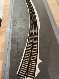
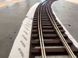
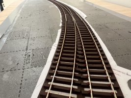
Job done for now.....this will not make it onto the layout, having built the first turnout, confident that I can do a better job second time around but in terms of testing the principle and techniques invaluable. I got a little bit lost around the V but so far smooth transit of the test coaches....

Martin - I absolutely salute your skills......this went together very nicely...sliding chairs are not pushed down just yet as I may want to adjust the switch rails...
 

Attachments

  • top.jpg
    top.jpg
    1.8 MB · Views: 75
  • end 1.jpg
    end 1.jpg
    1,008.3 KB · Views: 75
  • end 2.jpg
    end 2.jpg
    1 MB · Views: 76
_______________
message ref: 7332
The shorter angles for short diamonds and K-crossings will need a separate design, shorter but similar.

No they won't. Can now do any angle down to 1: 0.5 for short diamond-crossings (which is the shortest angle Templot can handle). This is for 1:1.5

new_jig6.png


I have reduced the overall sizes a bit to save printing time and filament.

The jig thickness can now be set to whatever you want to save print time and filament. Thin jigs down to about 10mm (i.e. 5mm per half) are usable, but thicker jigs up to around 25mm are easier to use with large files and likely to last longer with the wider filing face.

The default thickness is 18mm, i.e. 2 x 9mm. Actually it is 2 x 8.8mm, not 9mm, but the reason for that I will explain when I write about the Cura slicer settings for these jigs. Likewise the 0.88mm dimension showing on the jig, which is the depth of the groove for code 75 rail.

cheers,

Martin.
 
_______________
message ref: 7333
.
There is now an (optional) gizmo on the corner of the crossing rail filing jigs:


knuckle_guide.png


This is a gauging device to check knuckle bends after making them. Slide the rail into the slot, and you can check that the angle, length and radius of the bend are correct for this crossing angle. The rail should lie snugly flush against the gauge.

I will add an option to export this feature separately -- it could be resin-printed as a handy gauge tool.

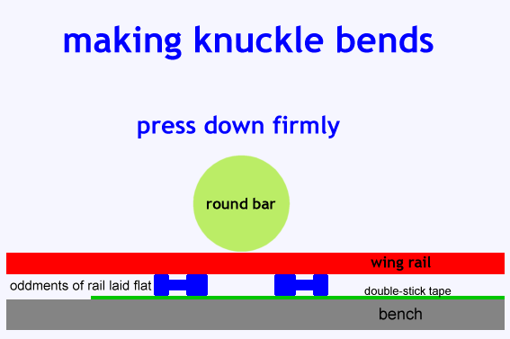
This is not a bending jig. It is for checking the bend after you have made it. For the bending I shall be doing some 3D bending jigs using sliding metal pins. Eventually. :)

In the meantime, the way to make a symmetrical radiused knuckle bend is:

2_041828_140000000.png


Lots more info about knuckle bends at:

https://85a.uk/templot/companion/knuckle_radius.php

cheers,

Martin.
 
_______________
message ref: 7337
I'm resin printing a combination of full chairs and loose jawed bricks with the intention of sliding some rails and dropping in some check rails etc. I'm using a Formlabs resin printer which is giving a slightly tighter chair/rail fit than I would like. can anyone point me in the direction of where I can adjust the chair/rail fit slightly?
 
_______________
message ref: 7339
I'm resin printing a combination of full chairs and loose jawed bricks with the intention of sliding some rails and dropping in some check rails etc. I'm using a Formlabs resin printer which is giving a slightly tighter chair/rail fit than I would like. can anyone point me in the direction of where I can adjust the chair/rail fit slightly?
@Terry Downes

Hi Terry,

Here you go:

dxf_rail_fit.png


That's a percentage adjustment to the rail web thickness setting. Positive changes make an easier fit in the chair. Negative changes make a closer fit in the chair. i.e. +100% would double the rail web thickness used in the calculations.

All chairs will be affected, with solid or loose jaws.

I haven't done much testing of this -- you will likely need some trial and error to see the effect. Try a short template of just one timber and use the preview to look at the chairs. You may also need to check the track gauge afterwards.

Please report your results, which rail section you are using, etc. -- this is still an experiment. I may have mentioned that before. :)

n.b. I suspect it's important not to have the rail a tight fit in the resin chairs, which might cause stress-cracking as the chair ages. They should slide along the rail without any resistance, but without significant play.

cheers,

Martin.
 
_______________
message ref: 7341
@Terry Downes

Hi Terry,

Having got the fit adjusted for the solid-jaw chairs, you may want to make a further small adjustment to the fit of the loose jaws:

lj_rail_fit.png


That doesn't change the jaw or pin, or the inner jaw on the chair, or the track gauge.

It simply changes the thickness of the key on the loose jaw. A positive dimension increases the key thickness, and so makes a closer fit on the rail. A negative dimension reduces the key thickness and makes an easier fit on the rail.

This dimension is in actual mm, not %, so you would normally enter a very small dimension, probably not much more than 0.05 mm.

cheers,

Martin.
 
_______________
message ref: 7347
.
The knuckle bend gauge tool thingy is probably better printed separately in resin than as an afterthought on the FDM filing jig:

kn_bend_gauge3.png


kn_bend_gauge2.png


kn_bend_gauge1.png

Allows checking the knuckle bend angle and bend radius. Drop the rail into the groove and it should fit snug against the gauge. The lowered section (showing darker blue) marks the limit of the bend radius.

Unlike the version on each half of the the filing jig, the groove is the full rail depth (plus a bit, can be set to whatever you want) for more positive location of the rail (turn the rail over to check the opposite rail).

Overall size is 40mm x 26mm, so should print directly on the build plate without any problems.

Or the STL can be FDM printed if preferred.

cheers,

Martin.
 
_______________
message ref: 7350
.
If anyone is visiting Scalefour Southwest in Wells, Somerset (part of the RailWells exhibition) this weekend:

http://railwells.com/railway-show/railwells-show-2023/

and would like to see plug track in the flesh, my friend Gavin Clark will have a few bits and pieces of plug track with him on his demo stand (RTR conversions).

cheers,

Martin.
 
_______________
message ref: 7352
Hi Martin,
is there any chance you could post a STL of the latest filing jig? Fully understand you going to release it with the next Templot update 241b, However your also working on some other additions required for this update.
It's simply I have been very busy pimping my old ender 3, It now has dual Z screws, linear rails for the Y axis, BTL touch probe,
New mother board and touch screen, so its well on its way to having the same spec as the new Elegoo Neptune 3 Filament printer.
As such I am now very keen to print something and was hoping to start with vee rail Jigs.
The STL of the 1in 8.5 is fine, but if its no real trouble 1.10 would be idea.
To be honest I am now even tempted to try some FDM printed timber bricks!
phil,
 
_______________
message ref: 7355
@Phil G

Hi Phil,

Here is an STL for 1:10 using these settings:

jig_settings.png


Using the Cura slicer (free) it's important for successful clamping that these two settings are both round multiples of the Layer Height set in the slicer. In this case the STL below is for 0.15 mm layers and code75 bullhead.

For a faster print you could use 0.22mm layers and say 0.88 groove, maybe 9.46 part thickness (when you get 241b). On the Neptune 2, 0.15mm layers produce a noticeably better result.

The rail head width is also important of course to match your rail. In this case however, you can adjust the rail fit using the Horizontal Expansion setting in Cura.

For best results you also need to change the Z Seam Alignment setting so that layers don't start or finish on the groove walls.

p.s. the Code 75 setting on the above dialog is purely for the data label, it plays no part in the jig design.

The STL has been fixed in 3D Builder and is ready for use:

jig_1in10.png


For a successful jig you need to be using Toughened PLA Plus polymer. This works great:

https://www.amazon.co.uk/gp/product/B07FQ75QG2

cheers,

Martin.
 

Attachments

  • filing_jig_for_0p15_layers_1in10_code75_fixed.stl
    152.8 KB · Views: 42
_______________
message ref: 7356
Hi Martin,
Thanks for the STL you post has lost me a bit on my Cura (5.4.0) I have layer height options of 0.12 (super quality)
0.16 (dynamic quality) and 0.02 (standard quality) I have been on the internet and read about something called adaptive layers. Is this what I need to set for a layer height of 0.15?
The other thing is I have measured the new rail I have just received from the EMGS and it mics up as 0.89mm wide, so should I use a groove depth of 0.88 or 0.90? Last thing I have PLA + is that the same toughened PLA plus polymer?
Phil,
 
_______________
message ref: 7357
@Phil G

Sorry Phil, I assumed that if you are into converting an Ender to a Neptune3 you would be well versed in Cura. Do you normally use a different slicer?

The user interface for Cura is a bit of a mystery tour (like Templot :) ), but it's all there in the end:

cura1.png


The first thing to do is click Marketplace top right. Download and install the Settings Guide. Then you can right-click on any of the settings and get a detailed explanation of what each setting does. There are only about 10,000 of them, so you will soon be up to speed.

Now go to Extensions > Settings Guide > Preferences. Untick Show articles in setting tooltips and restart Cura. Otherwise you will need a screen 5 yards wide to prevent the settings guide blocking out everything.

A collection of print settings is called a Profile. Click the down arrow on the current Profile to see all the other options. Click the hamburger (3 lines) and tick All and then Manage Settings Visibility... On that dialog tick Check all.

Now you can see all that is going on in Cura, and not just the dumbed-down selection of options that Cura thinks you would like.

Below I have attached the Profile which I'm using for the filing jigs on my Neptune2S.

Now some breakfast, then I will explain how to import it and use it. :)

cheers,

Martin.
 

Attachments

  • neptune2s_filing_jigs_aug2023_cura5p4p0.curaprofile
    1 KB · Views: 45
_______________
message ref: 7359
Hi Martin,
I do use Cura but to be honest I have never printed anything other than standard settings, So I have never dug too deep into it.(that may explain why I have never been to impressed with FDM printers,)
I will download the setting guide now, So I think that's taken any heat off you doing any further explanation for several breakfasts :)
cheers
Phil
 
_______________
message ref: 7360
Now some breakfast, then I will explain how to import it and use it. :)
@Phil G

Hi Phil,

The first thing to say is that Cura is very stroppy about associating a profile with a specific printer. This is because the .curaprofile file appears to contain only the differences from the standard settings for a given printer.

When you try to import a profile it will very likely tell you that it's not compatible with your printer. (There must be a way around this -- anyone?)

The solution is to create a custom printer with the default standard settings.

Click the printer list drop-down and click Add printer:


cura4.png


Click Non-UltiMaker printer (unless it is one):

cura5.png


Assuming you don't have a 3D printer networked on your system (in which case you won't be reading this), click the drop-down for Add a non-networked printer. Then scroll down to the Custom option and select Custom FFF printer.

(FFF = Fused Filament Fabrication)

A panel appears in which you can give it a name, whatever you like. Then click Add:


cura9.png


This dialog then appears, in which Cura wants to know about this printer. Copy all this information from your existing printer -- which you can find by going to the Machine Settings dialog for it.

Or change it as you wish. On the Printer tab I set the Y dimension at 220mm instead of 235mm because I'm using a glass bed and need to allow for the clips:


cura11.png


It's very likely that your printer is using the Marlin G-code interpreter. If not I think you would know about it and not be reading this.

You can leave the Printhead Settings unchanged.

Also the Start G-code and End G-code. Later you may want to edit these to get better Z zeroing and backlash adjustment, and I will post some files. But for now the defaults should work ok.

And for the Extruder tab:


cura12.png


Set the nozzle size (very likely 0.4mm) and the filament diameter. This probably needs changing to 1.75mm and is very critical to good results.

Finally click Next.

In fact nothing happens next. :confused:

Click the Preferences > Configure Cura... menu item:


cura13.png


Check that it mentions your new custom printer as the active printer, click Profiles and then Import.

You should then be able to import my downloaded .curaprofile file and get a successful result:


cura14.png


Click OK.

Now over on the right you need to select this profile to be used:


cura15.png


And finally you should see my suggested settings, ready for use:


cura16.png


Open the STL file and slice it in the usual way. :)

cheers,

Martin.
 
_______________
message ref: 7361
Hi Martin,
I have been doing quite a bit of research on the resin (I thought I better had given I am in the chemical engineering industry) There is no doubt the temp of the resin in the vat is critical to constant replication, This is because even though the reaction is between the chemicals and the UV light, the reaction profile is still directly temperature related. The ideal temp looks to be 25 to 26 degrees, but of more importance is you hold it consistently print after print. Ideally to within 1 degree. So its more critical to find your optimum temp, and then set the Templot adjustments to suit.
This mean accurate temp control is required. The attached link is what looks to me a very good way of doing it on the Mars 2. I have also found and started to make an equivalent for my Mars 3, using exactly the same electrical components.

https://www.elegoo.com/blogs/3d-printer-user-guide/elegoo-mars-2-pro-how-to-make-a-heater.

Just a foot note as Martin has pointed out its very likely a change of resin will result in a change of the reaction profile, especially if is its a different manufacturing batch. meaning if your planning to do quite a large amount of trackwork your be advised to purchase more then one bottle and check there from the same batch, failing that each new bottle will need a bit of fine tuning of the setting.
As to the FDM same issue but the temp is already about as good as you can get. my personal preference is to go with laser cut timbers.
that said I am a long way from proving that, due to the fume issue which has to be resolved. So to use Martins preferred explanation, "that is still very much experiment in progress " :)
I don't think laser will work without glue but given superglue is often used in the woodwork game, it does lend itself to this holding application.
Phil
 
_______________
message ref: 7366
Hi Martin,
I have been doing quite a bit of research on the resin (I thought I better had given I am in the chemical engineering industry) There is no doubt the temp of the resin in the vat is critical to constant replication, This is because even though the reaction is between the chemicals and the UV light, the reaction profile is still directly temperature related. The ideal temp looks to be 25 to 26 degrees, but of more importance is you hold it consistently print after print. Ideally to within 1 degree. So its more critical to find your optimum temp, and then set the Templot adjustments to suit.
This mean accurate temp control is required. The attached link is what looks to me a very good way of doing it on the Mars 2. I have also found and started to make an equivalent for my Mars 3, using exactly the same electrical components.

https://www.elegoo.com/blogs/3d-printer-user-guide/elegoo-mars-2-pro-how-to-make-a-heater.

Just a foot note as Martin has pointed out its very likely a change of resin will result in a change of the reaction profile, especially if is its a different manufacturing batch. meaning if your planning to do quite a large amount of trackwork your be advised to purchase more then one bottle and check there from the same batch, failing that each new bottle will need a bit of fine tuning of the setting.
As to the FDM same issue but the temp is already about as good as you can get. my personal preference is to go with laser cut timbers.
that said I am a long way from proving that, due to the fume issue which has to be resolved. So to use Martins preferred explanation, "that is still very much experiment in progress " :)
I don't think laser will work without glue but given superglue is often used in the woodwork game, it does lend itself to this holding application.
Phil
@Phil G

Hi Phil,

Thanks for the link and resin info.

I'm very pleased with my improvised heater for the Mars using a brewing heater belt and bungee cord:

https://85a.uk/templot/club/index.php?threads/3d-printers-messin-with-resin.103/post-7161

Linked to the Inkbird controller with its probe inside the printer cover, it is maintaining the temperature at exactly 25 degsC +/- 0.2 degs.

I'm so pleased with it that I've ordered a second heater belt to fit below the first one. That will take it to 50W total, which should be enough to lift the printer to working temperature even on the coldest winter days.

But not at present -- one warm day recently the printer's own generated heat took it to 26 degsC. At that point the Inkbird's cooling output came on, and I plugged in a desk fan pointing at the printer to prevent it going any higher. Which seemed to work -- but obviously wouldn't do if the ambient temperature was higher. That would make the 3D printing den unbearable, so I'm not likely to be doing any 3D printing on such days. But I must remember to put the bottles of resin in the fridge. :)

cheers,

Martin.
 
_______________
message ref: 7367
Martin all my work so far including the 80cm point i build have been with solid jaws. It was tricky holding the whole lot together why I slid in the rails and then dropped into the sleepers but it worked.
@Michael Woods

Hi Michael,

Thanks for your thoughts.

I'm now firmly convinced that the loose jaws option is an easier way of building track. It avoids all the hassle of preparing the rail ends, sliding chairs onto the rail in the correct order, spacing them out, locating them all over their sockets in one go, and holding multiple rails in place.

Take one chair at a time from the raft. Fix it in its socket. Simple. Drop the rails into position when you are ready, one at a time. Insert the loose jaws to clip them into place, again one at a time. There is a very satisfying click as each one locates into position below the rail head.

It sounds too fiddly for words -- but it isn't. With some magnifying specs and some fine point tweezers it's quite easy to do and you soon get into the hang of it. It takes a bit of time, but no more than you have already saved by not having to slide chairs onto the rails.

The trickiest part is keeping track of which loose jaw goes where. I found a useful container is an ice-cube tray. One row for the stock jaws -- S1, L1, P, SC. One row for the special jaws, in order, labelled, as you remove them from the raft.

Admittedly you can't build loose-jawed track while riding a galloping horse. It needs a quiet relaxed setting with some calming music, and a nice bunch of flowers in a vase on your bench. Just don't knock it over. :)

Despite wittering on about correcting fluid, I'm still pondering how to improve the press-fit option. It might be possible to run an angled barb along the side of the plug to retain it in the socket, rather than relying entirely on the interference fit at the ends of the plug. It can't be too fierce a fit on the socket sides, because in places the walls are quite thin and would bulge the timber sides. But it might be enough to prevent the plug coming loose. It could instead be an actual groove in the side of FDM sockets -- but that won't work for plywood.

So that's another experiment to be conducted, and another tick-box to control it, and another settings button for the barb dimensions. And on it goes. :)

cheers,

Martin.
 
_______________
message ref: 7368
'
A few days ago I obtained one of these:

https://www.amazon.co.uk/dp/B0080R1CLG

I was interested to see what quality could be expected for just £3. I thought probably not much.

But I was pleasantly surprised. It is actually a nicely made G-clamp. The frame is cast iron and substantial. The 1/2" dia. screw is a good close fit with very little play and a smooth action along its full length. The tommy bar is nicely finished with no sharp edges. The screw is actually chemically blackened rather than plated in the picture -- but blacking generally allows a better screw fit and retains lubrication better. The shoe is painted and swivels freely without excessive play.

Although labelled 50mm / 2" the actual maximum opening is 61mm / 2.3/8"

And the relevance to plug track is?

I've been thinking about the rail bending tools. They will have 2mm dia. dowel pins in FDM slides. I wondered if I could design them to fit onto a G-clamp frame, so that the screw could apply the bending force in a smooth controlled manner. This G-clamp looks very promising for that, and is inexpensive. Any thoughts? Is this worth a try, or another of my daft ideas?

p.s. yes I know they should correctly be called cramps when used to apply force. :)

cheers,

Martin.
 
_______________
message ref: 7370
Adhesives,
I have found that Gorilla wood glue bonds resin bases to card, cork and plywood quite adequately.
it contains: acetic acid ethenyl ester, polymer with ethanol; 1-phenoxypropan-2-ol;
2-methyl-2H-isothiazol-3-one
Whatever that means but it does seem to work.
Also when testing some L1 loose jaw chairs with increased socket size, I glued some loose ones into resin base with a dab of Glue'n Glaze from underneath(as I had it to hand). So this was resin to resin, and that also seemed to hold.

 Paint
Before, during, or after ballasting some form of painting will be required, both from applying the required colouring/weathering, and for UV protection . This will also help bond everything in place.

let's face it the previous method of using solvent to attach ABS chairs to plywood timbers was not fool proof, too much solvent and the detail of the chair disappeared, same with pressure, and gauge distortion with angled rail seats.

Is the key to a good bond between rail and slide chair a thorough decrease of the rail just before assembly and application of glue?

Steve
 
_______________
message ref: 7371
Back
Top