Templot Club forums powered for Martin Wynne by XenForo :

TEMPLOT 3D PLUG TRACK - To get up to speed with this experimental project click here.   To watch an introductory video click here.   See the User Guide at Bexhill West.

  • The Plug Track functions are experimental and still being developed. Some of the earlier pages of this topic are now out-of-date.

    For an updated overview of this project see this topic.   For some practical modelling aspects of using Plug Track see Building 3D Track.

    The assumption is that you have your own machines on which to experiment, or helpful friends with machines. Please do not send Templot files to commercial laser cutting or 3D printing firms while this project is still experimental, because the results are unpredictable and possibly wasteful.

    Some pages of this and other topics include contributions from members who are creating and posting their own CAD designs for 3D printing and laser-cutting. Do not confuse them with Templot's own exported CAD files. All files derived from Templot are © Martin Wynne.
  • The Plug Track functions are experimental and still being developed.

    For an updated overview of this project see this topic.   For some practical modelling aspects of using Plug Track see Building 3D Track.

    The assumption is that you have your own machines on which to experiment, or helpful friends with machines. Please do not send Templot files to commercial laser cutting or 3D printing firms while this project is still experimental, because the results are unpredictable and possibly wasteful.

    Some pages of this and other topics include contributions from members who are creating and posting their own CAD designs for 3D printing and laser-cutting. Do not confuse them with Templot's own exported CAD files. All files derived from Templot are © Martin Wynne.

Experimental 3D plug track - up to version 244c

Quick reply >
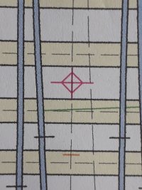
Templot has kindly printed a registration mark to indicate where to drill the hole that takes a 1mm veneer pin locating the toolbar of a timber base joining clip.
20230727_170111.jpg
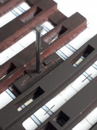
Here is the same location with the timbering bricks located on the plan with the veneer pin and stuck down.

20230727_170331.jpg
now for some chairs, but where to start?
 
_______________
message ref: 7241
Splice rail now fitted

20230727_201708.jpg


I again had trouble with the L1 chair, got through 5 before managing to get the loose jaw fitted.
As I applied downward pressure on the jaw, it snapped off leaving a sm as all but stuck in the slot, so had to keep replacing the chair. Perhaps I over-sized the L1 chair raft thus making them brittle.
Anyway managed in the end. The D loose jaw was easy in comparison.

About to fit the X chair, but having removed it from the raft cant tell which way round it should go.
Is it symmetrical?

20230727_201723.jpg


Steve
 
_______________
message ref: 7243
I again had trouble with the L1 chair, got through 5 before managing to get the loose jaw fitted.
@Steve_Cornford

Hi Steve,

Looking good. :)

The L1 chair differs from all the others in that the pin and slot run down at a 5 degree angle. It is helpful to know this when pushing on it:

l1_pin.png

The angle was necessary because of the closeness of the jaw to the end of the chair. There is also a slight vertical kink in the pin at the top. I left this in because I thought it might help to lock the jaw in place. Perhaps that was a mistake.

In my tests it worked ok. But of course you are using a different batch of resin, on a different printer, at a different temperature. It all adds up. That's why you may need to tweak the pin clearance settings to suit your conditions -- click the loose jaws... button:


l1_pin1.png


Those settings apply to all the loose jaws -- there isn't a separate setting for the L1 chairs. It now occurs to me that the angle on the pin may make a difference and require separate clearance settings for L1. I will get that option added in 241b. This is what I mean by still having so much testing and learning to do. :)

If a pin breaks off it should be a loose fit in the slot, and be easily pushed out with a bit of wire from the top or the bottom. On my chairs a broken pin will actually fall out of the slot with a shake. It is the key clipping against the rail which makes the tight fit.

If your pins are not loose enough to do that, it probably means you need to adjust the clearance settings as above.

We might perhaps print a pin pusher-outer tool.

Some other thoughts -- the angle may reduce the effectiveness of the washing. It would take only a thin film of uncured resin left in the slot to significantly affect the pin clearance. I have a full 2 litres of IPA in the first tub and vigorously plunge the plate up and down a few times to force wash through the slots before doing the normal rotary swirl wash.


The XN chair is only strictly symmetrical if its centre is exactly on the centre-line of the knuckle bend, and it is for a regular-pattern crossing. However the differences are very small in 4mm/ft scale, and probably smaller than the resolution of the printer. Which means it is effectively symmetrical for practical purposes. It might even fit better the wrong way, if the rounding effects of the printer resolution so conspire. It may also depend on which way round you have the raft on the build plate, across or along.

It's a good idea to run a marker pen along one end of the plugs while they are still on the raft.


How is the press fit of the chairs in the sockets? I have fretted more about that than the pin slots, so I'm a bit surprised that you mentioned the pin fitting and not the chairs.

Is that a resin-printed base which you have sprayed brown, or are you now FDM printing? :)

cheers,

Martin.
 
_______________
message ref: 7244
L1 chair
Washing.
Normally I also give them a "plunge" bath at the start, but perhaps I didnt on this occasion.
Also after the final wash I use a flexible straw and direct a jet of air down each slot to clear out any residue.
I will print a new batch of L1 chairs and be more rigorous with the "plung" bath and air flushing.

XN chair
Orientation.
HIndsight is a great thing. After I had removed from raft it did occur to me that I should have run a marker pen down one side as you have suggested.
That is definitely a tip worth mentioning for the common crossing chairs in any future Step by Step Guide.
I subsequently did this for a raft of a set of check chairs to make life a bit easier.
Now come to think of it, a marker pen along the outer side of each of the CCL and CCR chairs would make life even easier, although of course we just remove and fit one chair at a time so that we are using the corresponding jaws.

Chair press fit
Thats has been fine so far, there is a satisfying little click as you press the chair home with the end of a saw off cocktail stick.

Timber bases
These are resin printed then sprayed with a Halfords rattle can.
Resin bases are just for my experiments whilst I prevaricate over getting an FDM printer, which I am sure would be useful if only for printing the various jigs you have in mind.
Rather than amend the z shrinkage, I increased the depth of the timber base within Templot to 3.5mm to compensate for the "apparent loss of layers" to get the finished article close to the design objective of 3.2mm. *note to others, this is only when printing resin bases, this is NOT necessary for FDM printed timber bases.

Still having fun though, Steve
 
_______________
message ref: 7245
@Steve_Cornford

Hi Steve,

A further thought. I remember wondering about this months ago, but then forgetting to do anything about it.

The pin slot in the L1 chair is very close to the end of the plug. It's possible that pressing the plug into the timber could be deforming the plug and compressing the slot. I suspect this is more likely when pressing resin into resin, rather than resin into FDM or plywood. Especially in situations where two L1 chairs are close together, outer end to outer end, as on the vee rails. There might be a case for a dummy single chair/plug to represent two close-spaced L1 chairs.

Could you check if there is any difference in the fit of the pins in the L1 slots, before and after pressing them into the base? Thanks.

Now that folks are beginning to use plug track for real, an obvious frustration must be not having most of the settings changes preserved between sessions. The current save custom buttons don't save much more than the rail section data. I think it would be better if the plug track settings were included in the existing program preferences mechanism, so that they can be loaded automatically if desired, and several different preferences files can be created. I will try to get that done for 241b, although there are now so many settings that it will be several days work. Also, it's difficult to decide which settings should be template-specific (like the chair jaw options), and thus saved in the BOX file instead. There is also the entire chair heaving function to think about and the options to create custom chairs. It will all need saving between sessions. And the 3D stuff in the background shapes, which would be better saved separately from BGS3 files.

At present I'm working on the filing jigs, but not very rapidly with the improved summer weather. Your filed vee rails look a good fit in your photos, do you have existing metal jigs?

cheers,

Martin.
 
_______________
message ref: 7247
Hi Martin,

This is all getting quite exciting, although there is still no way I can have a resin printer!

Just a thought on this:-

Now that folks are beginning to use plug track for real, an obvious frustration must be not having most of the settings changes preserved between sessions. The current save custom buttons don't save much more than the rail section data. I think it would be better if the plug track settings were included in the existing program preferences mechanism, so that they can be loaded automatically if desired, and several different preferences files can be created.

Would it be better to keep program preferences separate from plug track preferences? I'm thinking of the situation where people use different rail sections so would want to save those preferences, but then not have to remember to update any program preferences if a change is made but to a different preference file.

A sort of analogy is that you don't keep printer calibration settings as part of the main program preferences but as separate files.

I'm thinking that Templot would open with the normal saved program preferences, then if a user wanted to use plug track or even just timber bricks then a separate settings file would be loaded - again in the same way we load any one of a number of printer/paper settings. I envisage lots of plug track/timber brick settings files to choose from!

I may have misunderstood your intention entirely, of course!

Cheers,
Paul
 
_______________
message ref: 7248
Just washing a new batch of chairs.
Plunge bath , tick
First wash, tick
First blow through, WIP

20230728_103006.jpg


I have printed one L1 raft across the build plate, and one along.

I will try fit of jaw whilst chair still on raft, and then once inserted.
Repeat for both orientations.

Yes I used a Scalefour metal folding jig, although to be honest the jig is not perfect as it does not support the whole depth of the rail.
The slot could be deeper, and then a recess where the clamping bolt goes through so that the effective depth of the slot where the rail is clamped is the same as now. I expect your design is better.
Sreve
 
_______________
message ref: 7249
Hi Martin,

This is all getting quite exciting, although there is still no way I can have a resin printer!

Just a thought on this:-


Would it be better to keep program preferences separate from plug track preferences? I'm thinking of the situation where people use different rail sections so would want to save those preferences, but then not have to remember to update any program preferences if a change is made but to a different preference file.

A sort of analogy is that you don't keep printer calibration settings as part of the main program preferences but as separate files.

I'm thinking that Templot would open with the normal saved program preferences, then if a user wanted to use plug track or even just timber bricks then a separate settings file would be loaded - again in the same way we load any one of a number of printer/paper settings. I envisage lots of plug track/timber brick settings files to choose from!

I may have misunderstood your intention entirely, of course!

Cheers,
Paul
@Paul Boyd

Hi Paul,

Thanks -- I'm still pondering all this. The main thing I imagine most folks require is that their settings get preserved across Templot sessions without them having to do anything, but can be easily changed if necessary.

The existing save program preferences function allows for multiple different preferences files, so it would be possible to create different files where only the 3D settings are changed, or others where only the main program settings are changed:


preferences_files.png


But maybe as you say it would be better to keep the existing separate 3D functions:

custom_dxf.png


Those buttons create SK4 files, and it's possible to create as many as you wish and load whichever one you want at any time. We could have (yet another) reminder, to click the button before quitting if settings have been changed, and on start-up if a saved SK4 file exists.

Possibly combine the two approaches, so that the existing program preferences could include an option to load and/or save a preferred SK4 file automatically. Or not. Or something else. Templot just goes on getting more and more complex exponentially. :)

cheers,

Martin.
 
_______________
message ref: 7250
Just washing a new batch of chairs.
Plunge bath , tick
First wash, tick
First blow through, WIP

View attachment 6413

I have printed one L1 raft across the build plate, and one along.

I will try fit of jaw whilst chair still on raft, and then once inserted.
Repeat for both orientations.

Yes I used a Scalefour metal folding jig, although to be honest the jig is not perfect as it does not support the whole depth of the rail.
The slot could be deeper, and then a recess where the clamping bolt goes through so that the effective depth of the slot where the rail is clamped is the same as now. I expect your design is better.
Sreve
@Steve_Cornford

Thanks Steve.

I'm a bit puzzled by your "blow through" process? I use an air blast gun to dry off the IPA in one go after washing, but I think a hairdryer would work just as well. Blowing through each slot individually must be very tedious -- does it make a detectable difference? After washing there shouldn't be any uncured resin left in the slots -- if there is it needs more washing, because I wouldn't think just blowing would remove it?


I use 4 washes all told:

First off a "dirty dunk" in an old pie dish or loaf tin with a brush over the back of the build plate to remove the bulk of the surplus resin. This IPA is re-used and is a very cloudy grey, but it still works to remove the bulk of the surplus resin and dilute what remains. Kept in a jam jar between sessions.

(I've been intending to FDM-print some stand-off thingies to clip onto the corners of the build plate so that it can stand in the pie dish without damaging the chairs. Another job on the to-do list. Otherwise it must be held by hand above the dish to keep the chairs safe.)

Second wash is in the first Mercury wash tub, with much initial plunging. This IPA is just visibly cloudy, but not much.

Third is in the second Mercury wash tub, again with much initial plunging. This IPA is almost clear.

Finally I pour a little fresh IPA across the build plate and catch it in the second Mercury tub.

While all this is going on, if you have a second build plate the next job can be printing.

Every few months the washes get cascaded down the chain, and I start the second Mercury tub with fresh IPA.

The old "dirty dunk" is stored in glass jam jars for the "sunshine recycle" process, although I haven't had much success with that. It's very messy and difficult to filter.

I've stopped using a brush to wash the actual chairs. In the uncured state they are quite soft and easily damaged. It's too easy to despatch the loose jaws to the far side of the room! Once UV cured they are much harder, and get harder still after a few hours.

With all this IPA sloshing about I have a fire extinguisher close by, just for peace of mind.

cheers,

Martin.
 
_______________
message ref: 7253
Not too tedious, and normally I do it in the garden, quite a bit of ipa flows out of the slots. Once done I go indoors and use a hairdryer to complete the drying.
I think an FDM printer will take priority over an air blast gun for me though:)

I do have a second buid plate which is useful
Cheers Steve
 
_______________
message ref: 7255
Hi Martin,
There is a significant difference comparing inserting the loose jaw when the L1 chair is still on raft (ie not plugged into base) with attempting to insert loose jaw with the L1 chair aleardy plugged into the resin timber base, so I think you aer correct about the resin bases compressing the chair sufficiently to deform the slot and thus inhibit the loose jaw pin.
The other chairs do not suffer from this problem. Dont worry unduly though as you have already given me the means to combat this with some parameter tweaks.
Cheers Steve
 
_______________
message ref: 7256
@Steve_Cornford

Hi Steve,

Many thanks for reporting that -- it shows the value of such feedback. :)

Bear in mind that if you change the settings at present, it will apply to all the slots, not just L1.

Now to discover how much similar change takes place in FDM and plywood bases. Then what to do about it -- it's likely to be difficult to quantify.

Thanks again,

cheers,

Martin.
 
_______________
message ref: 7257
@Phil G

Here we have the revised design for the filing jig for the crossing rails. The jig for the switch blades will be similar, but longer -- not yet done.

This design will do any angle flatter than about 1:4 -- whatever is set. For shorter angles for short-angle diamonds it will need a separate shorter design with different hole centres.

This is 1:7.5
new_jig1.png


This is 1:16
new_jig3.png


new_jig2.png


The data panel is a bit cryptic in 7-seg format. The small square is a decimal point, so this one is for 1:7.5 angle.
The rail size is 1.90mm height x 0.91mm width.

The holes are a fraction under 6mm square. Intended to have M6 roofing bolts bashed through as alignment dowels. Plus penny washers and wing nuts to clamp the rail.

The overall size of the assembled jig is 100mm x 50mm x 22mm. The two halves are printed at the same time in a single STL for best match of the finished dimensions. The linking tabs are just to keep the slicer happy -- they get trimmed out of course. The lower area is for holding the assembled jig vertically in a bench vice.

More info when I have actually printed one. :)

Here is the previous longer design for comparison. The spanner is a bit over-the-top -- finger-tight wing nuts clamp the rail just fine.

index.php


index.php


cheers,

Martin.
 
_______________
message ref: 7258
Hi Martin,
This may be of interest.... I have been using the below design, which has evolved over several uses but, it shows that one jig/print can be utilised to file vee, crossing and blades by utilising both sides of the jig. the vertical cut through is very useful for confirming where the wedge end should be etc. I usually sandwich these in a vice between 2 plates of steel to reduce the wear on the jig.
1690617998057.png
 
_______________
message ref: 7260
That looks really good Martin.

Would there be any chance of adding another rail groove in each half that ran parallel to the longest side about half way down the shortest side please?

That would enable you to clamp (once they were filed) a point rail and a splice rail together to:-
A) check fit
B) use as a soldering jig for those wishing to use non plug track forms of assembly

Steve
 
_______________
message ref: 7261
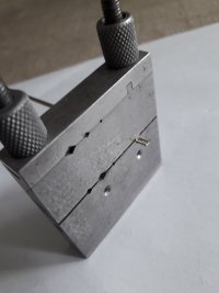
ps forgot to say that the end of this parallel slot can also be used as a filing jig to get a nice square end on the rail, similar to this device that I currently use:-
20230729_101918.jpg
I have poked the bit of rail further out just to make it obvious.

And as a result of scrambled egg this am a further thought, if there was also a pair of slots just 22mm long or thereabouts, it could be used as a bending jig to get the 12mm flare on the end of check/wing rails....
Steve
 
_______________
message ref: 7262
That looks really good Martin.

Would there be any chance of adding another rail groove in each half that ran parallel to the longest side about half way down the shortest side please?
@Steve_Cornford

Thanks Steve.

There's a bit of a problem with soldering jigs. The filing-resistant PLA+ polymer for FDM printing is not remotely resistant to soldering temperatures and would soften and distort if clamped tight onto hot rail. A resin print would be much better as a soldering jig. On the other hand the resin is not remotely resistant to being filed. Terry says he is clamping his filing jigs between metal plates for that reason.

So a combined filing/soldering jig is not very practical.

My feeling is that the best way to check the rails for alignment is to try them in the crossing chairs. Especially for a curviform crossing where the radius differs in the two rails. If a soldered vee is wanted, that is also probably the best place to do it too, i.e. in situ with a little SMT paste. The resin chairs would protect the FDM timbers from the hot rail. As they would when attaching dropper wires -- although with plug track the droppers can be attached before assembly, allowing a much neater connection to the bottom of the rail.

But I'm hoping that with accurate filing jigs exactly matching the crossing angle there will be no need for soldering -- the vees are not soldered in the Finetrax kits for example. Perhaps after assembly and testing the vees might be sealed with penetrating cyano or enamel paint, although just the required scoosh of rattle-can paint is very effective at sealing the rails and loose jaws in place.

I like the idea of a square rail end filing jig, for those who don't have a disc sander -- or even if they do. It can probably be made a hand-held tool with just a single clamp bolt.

For the bending jigs for knuckles and flares I have some ideas based on metal dowel pins in FDM sliders:

https://www.amazon.co.uk/Stainless-Steel-Dowel-Parallel-Dowels/dp/B07VQ4S4PS

But not yet tried.

Lots of things still to think about. But probably the next priority ought to be the slab & bracket chairs.

cheers,

Martin.
 
_______________
message ref: 7264
Sorry, I pressed send prematurely there... I meant to ask what type of chairs are missing from my scissors crossover shown below? I assume they are DN, A & B chairs but, are these slab and bracket?
1690644682986.png
 
_______________
message ref: 7266
Martin, do You think You will be programming the slab and bracket chairs before the remaining crossing chairs e.g. L1CC, DN, DA, DB
@Terry Downes

Hi Terry,

I want to get the slab & bracket chairs done as soon as possible so that I can legitimately say that the REA V-crossings are finished, and thus full REA turnouts are now possible. There are a few other details to finish still -- fishplates; switch drive arrangements (tie/stretcher bars); switch anchors; the infill piece for between two loose jaws; etc. However many such items are already available from the model trade, or modellers have their own methods, so maybe not the same urgency to get the plug track versions done.

For the K-crossing chairs, that's quite a major fresh task. Not least because of the Templot options to have the point rail timber in the prototype position, or in the model position to allow for wider than scale flangeways. I can see some such issues to be resolved for the fixed K-crossings, so I will probably do the switch-diamonds first. I doubt I will get very far on with any of this before the autumn. Nowadays I tend to measure timescales in terms of prime ministers. :)

But I do want to get on to the K-crossings, slips and diamonds, because it is those which fully demonstrate the advantages of plug track's vertical rail assembly rather than sliding the rail in from the ends.

The L1 check rail chairs are on the back burner for now. They will come eventually, but it wouldn't be wise to hold your breath. There is also the pin slot sizing issue for L1 chairs (see Steve's post) to be sorted out first.

Also currently on the back burner for some time has been the CNC milled timbering bases. I don't want to let that option disappear entirely from view and I'm keen to get back to it before long.

Your filing jig looks great. Can you say a bit more about it? If it needs metal protection plates, presumably that's a resin print? I'm not too clear why you have two vee slots for 1:11 ? Or is the other slot for a different angle? Are those slots full rail depth with a plain clamp plate, or have you mirrored top and bottom half-jigs like Templot?

cheers,

Martin.
 
_______________
message ref: 7267
Hi Martin,
1690651050622.png

Does this parameter effevtively make the L1 sockets smaller (lengtwise alone the timber)?
I notice that the default "normal socket end clearance" is also [-0.05], wheras longand very long sockets default is [-0.01]
Steve
 
_______________
message ref: 7268
Hi Martin,
View attachment 6432
Does this parameter effevtively make the L1 sockets smaller (lengtwise alone the timber)?
I notice that the default "normal socket end clearance" is also [-0.05], wheras longand very long sockets default is [-0.01]
Steve
@Steve_Cornford

Hi Steve,

Is that in the current release? I've got in a muddle again. I didn't think I had released that. :confused:

Yes, that adjusts the length for short sockets, such as for the L1 chairs. To ease the chair fit you need to make that more positive (less negative). I would suggest trying [-0.02] and seeing if that eases the slot compression problem. If you set it to zero there will be no press-fit, the plug will be size-for-size with the socket. If you make it positive it will make the plug loose and leave room for some glue.

Note that this changes the size of the socket, not the chair plugs, so you need to print a fresh timbering base. Any other chairs with short plugs will also be affected, but at present there are none, only the L1 chairs.

Note also that at present the change won't be preserved across Templot sessions, you will need to make the change every time. That's another job on the list. Some days it just all seems too much. I should have mentioned this option yesterday, sorry.

cheers,

Martin.
 
_______________
message ref: 7269
Hi Martin,
Yes it is in the current release.
I am just trying to understand all the options.
I tried printing some L1 jaws with the three loose jaw pin clearance parameters that you highlighted increased from the default by 0.01, but I think this makes the pins too weak, so perhaps I will try again but this time only increase the "front-inner" by 0.01, making it a clearance 0.02mm
Perhaps i will also generate a raft with the slot size increased from 0.6 to 0.62.
But first I have to cook supper!
Steve
 
_______________
message ref: 7270
Hi Martin,
Yes it is in the current release.
I am just trying to understand all the options.
I tried printing some L1 jaws with the three loose jaw pin clearance parameters that you highlighted increased from the default by 0.01, but I think this makes the pins too weak, so perhaps I will try again but this time only increase the "front-inner" by 0.01, making it a clearance 0.02mm
Perhaps i will also generate a raft with the slot size increased from 0.6 to 0.62.
But first I have to cook supper!
Steve
@Steve_Cornford

Hi Steve,

Bear in mind that changing the pin/slot sizes will affect all chairs, not just L1.

cheers,

Martin.
 
_______________
message ref: 7271
A resin print would be much better as a soldering jig. On the other hand the resin is not remotely resistant to being filed.

Oops, a generalisation too far I fear!

True for some resins, but if you need a tough print, use a tough resin - I used Siraya Tech Build for a recent job because it is very abrasion resistant, has high yield, low modulus and it takes detail very well. Which would make it too brittle for chairs, but perfect for a filing jig! There are many, many different resins available and it makes sense to me to only use those which publish mechanical properties and to select carefully according to the final purpose. To complicate matters, most of the (eg) Siraya Tech resins can be mixed to achieve intermerdiate properties. Unfortunately, the very best resins are not cheap, but then we need adequate, not best!

I have noticed people say that the prints they have made are "weak" and wonder what led them to their particular choice of resin for the job? Personally, for chairs (which I have yet to have a go at !!), I might be tempted to invest in a bottle of Siraya Tech Tough for a first go as it has a high elasticity, and blend it 50:50 with the Build to avoid too much plastic deformation in the resultant prints.

No good for a filing jig though ...

Watching with interest!
Howard
 
_______________
message ref: 7272
Hi Martin,
Point taken. At the moment Templot doesnt save these pararmeter settings between sessions, and I am only generating some L1 rafts in this session.
Back to cooking my venison now that the spuds are nearly done.
Steve
 
_______________
message ref: 7273
Last edited:
Oops, a generalisation too far I fear!

True for some resins, but if you need a tough print, use a tough resin - I used Siraya Tech Build for a recent job because it is very abrasion resistant, has high yield, low modulus and it takes detail very well. Which would make it too brittle for chairs, but perfect for a filing jig! There are many, many different resins available and it makes sense to me to only use those which publish mechanical properties and to select carefully according to the final purpose. To complicate matters, most of the (eg) Siraya Tech resins can be mixed to achieve intermerdiate properties. Unfortunately, the very best resins are not cheap, but then we need adequate, not best!

I have noticed people say that the prints they have made are "weak" and wonder what led them to their particular choice of resin for the job? Personally, for chairs (which I have yet to have a go at !!), I might be tempted to invest in a bottle of Siraya Tech Tough for a first go as it has a high elasticity, and blend it 50:50 with the Build to avoid too much plastic deformation in the resultant prints.

No good for a filing jig though ...

Watching with interest!
Howard
@JFS

Hi Howard,

I should have made clear that I was referring to the Elegoo "ABS-like" resin which we have been using for the chairs.

I know there are dozens of different resins available (and polymers for FDM printing), but swapping resins is a messy and expensive business. It is really only for those who have made 3D printing a hobby in its own right. With plug track I'm trying to cater for those who primarily want to build model railway track, and the 3D printer is just a tool needed for that purpose.

For my own use the filing jigs will be FDM printed, but the STL files are there for anyone to try other methods if desired.

We may yet find that there are better resins for the chairs than the one we have been using, but we have had excellent results with it, and there is so much else for me still to do rather than get bogged down in testing different resins and home-brew mixes. But reports of results with other resins welcome.

The one resin property which is mostly on my mind is long-term embrittlement from ageing/UV/stress. It would be a disaster if someone used plug track for a lifetime project and then found their track falling to bits after 20 years. Any information you can provide on that would be very welcome, although I expect the answer is that no-one has tested any resin for long enough to know.

In the meantime I would urge that the rail-fit dimensions are adjusted so that the rail is a close fit in the chairs but not too tight, allowing the rail to slide easily but without excessive play. This should avoid any long-term stress cracking -- especially from thermal expansion/contraction of the rail. For P4 it may need to be a closer fit than for other gauges to ensure the P4 tolerances are met.

cheers,

Martin.
 
_______________
message ref: 7274
  • good
Reactions: JFS
Hi Martin,
Interesting result with the preview option when outputting a sort L1 timber base:-
1690705651009.png

3D builder however worked fine having performed the actual STL export and repair:-
1690706337709.png

At first I thought I had got my templates mixed up, but it is possibly just a quirk of the viewer. I still like it though.
Steve
 
_______________
message ref: 7275
@Steve_Cornford

Hi Steve,

I thought I had fixed that bug -- obviously not. It's caused by having two duplicate templates superimposed. Or at least, it was the last time, I will have another look. Thanks for reporting it.

I'm now convinced that the repair function in 3D Builder is identical to the one in the Formware online service (and my local copy of it), and produces exactly the same results. That means it is possibly available in a code library somewhere and possibly open-source. Which means I could possibly incorporate it directly into Templot if I can find it. But so far no luck -- Microsoft has a 10-year-old 3D printing SDK from which I might be able to extract it, if I knew what I was doing in Microsoft SDKs. Anyone?

https://www.microsoft.com/en-us/3d-print/sdk-app-downloads
https://learn.microsoft.com/en-gb/samples/microsoft/windows-universal-samples/3dprinting/


After fixing a Templot STL in 3D Builder it is possible to edit it or add additional features if desired. Here is the User Guide:

https://www.microsoft.com/en-us/3d-print/3d-builder-users-guide

cheers,

Martin.
 
_______________
message ref: 7276
Hi Martin,
I dont think I have two templates superimposed, but here is the box file if you want to check it
In the [3D] window, I had selected the same colour as SL077 in the box. (Column 2, row 2 in your pop-up colour choice), thenin the export window, selected to print that colour, timbers only
Steve
 

Attachments

  • oo-sf_lh-b8_2023_07_30_1355_12.box
    257.5 KB · Views: 48
_______________
message ref: 7277
@Steve_Cornford

Hi Steve,

Thanks for the BOX file.

There appears to be 3 templates with that brick colour, numbers 22, 23, 24 in the box.

If you select that brick colour in the DXF export, it will try to export all 3 of them on top of each other.

I can see that you have changed the jaw options for each, but that doesn't make any changes to the timbers or sockets. To export the timbers only, one of them needs to be in a different brick colour and be exported by itself.

A way to avoid the hassle of that would be to group just one of them, and then use the group option on the DXF dialog instead of the brick option. To group just one template, click on it and press G. At present that seems the best way of avoiding the bug -- there is still something not right with the all-L1 chairs which I need to fix. :(

When we have reached the stage where we know for sure that plug track actually works, I want to revisit this tangle of settings and options which has grown along the experimental way and simplify the whole thing. Hopefully with just a few buttons to create timbering bases, or solid or loose jaw chairs.

But there is still a lot to think about. For example, one area I have given no thought to at all yet is the chairing of gaunt turnouts. They are used as partial templates in some of the tandems, so can't be completely ignored.

For now, I'm concentrating on the filing jigs. :)

Thanks again,

cheers,

Martin.
 
_______________
message ref: 7278
Sorry Martin, I had a senior moment.
Ir was not the yellow ones, but the SL079 one which is coloured 4th column 3rd row or in rgb speak 0,128,128
Get same result if i select it as the only item in group & perform group export, or if i expoert by colour.

In fact it is a copy of SL077 but moved to a completely different place to try & see if there was an overlap.
SL077 is actually a different shade of yellow(255,255,0) from the other two(255,255,128)
Steve
 
_______________
message ref: 7283
And now for some good news.
I tried printing a resin L1 timber base with the "short socket end clearance" set to [-0.02] as you suggested, and as you expected the chairs tended to be a loose fit & fall out unless glued, but the default L1 loose jaws fitted without problem.
I then tried another L1 timber base print with the "short socket end clearance" set to [-0.03] and the chairs no longer fell out, but I was still able to insert the default loose jaw pins ok.

I could do with slightly larger diameter cocktail sticks. It does help if afer chopping the point off the stick a small v shaped groove is filed in the end which just helps the end not slipping off the top of the jaw.
I think your idea of a 3D printed "Jaw pusher" would help.

But for now I hope you are having fun with the Filing Jigs!
As its miserable outside I am having fun putting knuckle bends and set bends into rails using your suggestion of a jig composed of a couple of offcuts of rail stuck to a board in parallel at the requisite distance as you have illustrated on her before the advent of plugtrack.
Steve
 
_______________
message ref: 7284
But for now I hope you are having fun with the Filing Jigs!
@Steve_Cornford

Sure am. I have chopped a hole in it:

new_jig4.png


This saves some printing time and some material.

But the actual reason is to allow it to be clamped on the corner of a table with a small G-clamp, rather than needing a full bench vice to hold it. For those building track on a coffee table. :)

On the printer now. It's finally stopped raining, so I may risk leaving it running while I go for a short walk before the next lot of rain.

cheers,

Martin.
 
_______________
message ref: 7286
@Michael Woods

Hi Michael,

Thanks for the link. I have seen it before, but unfortunately I'm not a professional software developer and it's all a bit alien to me. C++ is well outside my comfort zone (Templot is written in Pascal), so it is going to take me a while just to decide whether it contains what we want. Then porting it into Pascal, or creating a linked DLL, will be no 5-minute task.

For the present I'm minded to let matters lie while I still have so much else to do. In the next update I have got 3D Builder opening straight from Templot (like the STL preview), and arranged a means of keeping its fixed STL files separate from raw STLs. But it relies on STL files being associated with 3D Builder. Provided folks don't have 3D Builder pre-installed, and therefore they download and install it, everything should work fine. If it is pre-installed, the best advice is probably to uninstall it, and then download it fresh.

Which is all a bit clunky, and if I could get the mesh-fixing working automatically in Templot that would be great. Time will tell. :)

Thanks again.

cheers,

Martin.
 
_______________
message ref: 7289
Wthin Templot the text characters are limited to:-
the numbers: 0,1,2,3,4,5,6,7,8,9
the letters: A,C,E,F,G,H,L,P,U
the characters: minus,equals,underscore
the # character gets translated to minus
all other characters get translated to the "unknown" character which is three horizontal bars of segments (of the 7 segment display paradigm)

1690797930661.png

Here is a 4mm L1 fixed jaw chair raft with a text label #4#L1#F to identify it. This has an exagerated text height of 5mm.
I suppose I should have put 75CL in their to represent suitable for code 75 C&L rail.
Steve on a rainy day
 
_______________
message ref: 7297
Back
Top