Templot Club forums powered for Martin Wynne by XenForo :

TEMPLOT 3D PLUG TRACK - To get up to speed with this experimental project click here.   To watch an introductory video click here.   See the User Guide at Bexhill West.

  • The Plug Track functions are experimental and still being developed. Some of the earlier pages of this topic are now out-of-date.

    For an updated overview of this project see this topic.   For some practical modelling aspects of using Plug Track see Building 3D Track.

    The assumption is that you have your own machines on which to experiment, or helpful friends with machines. Please do not send Templot files to commercial laser cutting or 3D printing firms while this project is still experimental, because the results are unpredictable and possibly wasteful.

    Some pages of this and other topics include contributions from members who are creating and posting their own CAD designs for 3D printing and laser-cutting. Do not confuse them with Templot's own exported CAD files. All files derived from Templot are © Martin Wynne.
  • The Plug Track functions are experimental and still being developed.

    For an updated overview of this project see this topic.   For some practical modelling aspects of using Plug Track see Building 3D Track.

    The assumption is that you have your own machines on which to experiment, or helpful friends with machines. Please do not send Templot files to commercial laser cutting or 3D printing firms while this project is still experimental, because the results are unpredictable and possibly wasteful.

    Some pages of this and other topics include contributions from members who are creating and posting their own CAD designs for 3D printing and laser-cutting. Do not confuse them with Templot's own exported CAD files. All files derived from Templot are © Martin Wynne.

Experimental 3D plug track - up to version 244c

Quick reply >
@Phil G @Steve_Cornford

Hi Phil, Steve,

I don't want to comment too much on all this until I have had a chance to build a full V-crossing. That should be possible in a day or two, at least for 1:5 (which doesn't need a CD chair).

But I'm puzzled to see what is the problem you are trying to solve? I have had no difficulty cutting chairs from a raft one at a time with the blue cutters, dropping them into their sockets, and tapping them home using a blunted cocktail stick. It's then easy to build the rails into them knowing that they are not going to move. Admittedly the loose jaws are a bit fiddly until you get the hang of them, but no more so for chairs in the timbers than for chairs on a raft.

If the NC nose clamp needs some tool or jig for handling I will create one, but at present I don't see why it should need more than a bit of Blue-Tack.

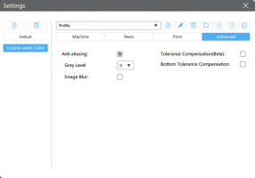
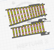
If you are sliding the vee rails into position, the NC doesn't need to move and can be left in its printed position midway between the chairs. Or supported there on the said temporary bit of Blue-Tack between the timbers. For sliding rails you would change the options to solid jaws on the CD and EF chairs, leaving loose jaws for the wing rails on chairs AA and BB. That's why there are all those tick boxes, so that you can change the options to whatever you want. They haven't yet been fully tested -- and can't be until I have got all the chairs done.

In many cases sliding the vee rails won't be possible. It's fine for a single turnout, just like a turnout kit. It may also be possible with a bit of pre-planning elsewhere -- for example if building a crossover in situ, you can slide in the vee rails if you do it before installing the chairs for the turnout-road stock rail on the opposite turnout (or if those chairs are all loose-jaw and you haven't yet installed the rail).

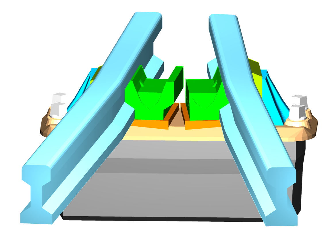
But often in complex formations sliding the rails into position will not be possible. That's the whole point and purpose of plug track, so that the rails can be dropped into position vertically, just like the prototype. Having a pre-built chaired vee might avoid that in some cases, but not all.

Sliding rails also involves the tedious business of filing unprototypical chamfers on the rail end to ease threading. Rails dropped into position don't need that, and it's a joy to build track with crisp flat rail ends, just like the prototype, and no sore fingers from chair threading:

index.php

cheers,

Martin.
 
_______________
message ref: 7024
I am using C&L code 75 and ABS like resin, and I found it quite hard to slide the rail through more than about 3 chairs attached to a raft.
So for assembling lengths of plain track I fb ound it easier to snip off one chair at a time then slide onto the rail, then plug the rail and chairs into the bases.
However I agree with Martin that when assembling turnouts loose jaws seem to be the answer as it allows crisp ends to the rail.
 
_______________
message ref: 7025
I am using C&L code 75 and ABS like resin, and I found it quite hard to slide the rail through more than about 3 chairs attached to a raft.
So for assembling lengths of plain track I fb ound it easier to snip off one chair at a time then slide onto the rail, then plug the rail and chairs into the bases.
However I agree with Martin that when assembling turnouts loose jaws seem to be the answer as it allows crisp ends to the rail.
@Steve_Cornford

Hi Steve,

I'm wondering if your chairs are closer-fitting than mine?

It's next to impossible to describe the fit of chairs in words. If I put some of mine on a length of rail, and stand the rail on end, most of them will stay put. A few will fall down a bit. If I tap the rail on the bench, they will all slide to the bottom.

This applies for solid-jaw chairs, and also for chairs with loose jaws fitted.

Perhaps it could be described as "Doll's House curtain-rail fit". :)

Now this will obviously vary with different batches of rail, and any oiliness left on the rail -- my rail is cleaned in white spirit and wiped dry. It is nickel-silver rail from C&L, several years old.

I suspect it's quite important to have chairs with an easy fit on the rail. Any residual stress in the chairs could cause long-term stress fractures and failure. Which would be a disaster on a lifetime layout project. It would be awful if my work on plug track led to such an outcome for anyone. :(

Any looseness in the chair fit will be taken up when they are painted. Resin-printed chairs will need a good scoosh of paint to protect them from UV embrittlement.

Apart from the fit adjustment in Templot, there are settings in the slicer which affect the "skininess" of the chairs. On the Mars 2 Pro I'm using a 2.2 second exposure, where I know others are using 2.5 seconds:

mars2pro_set1.png


It's also very important for accurate dimensioning of engineering parts to have the anti-aliasing switched off:

mars2pro_set2.png


It is on by default in several slicers -- presumably to produce well-fed toy soldiers.

cheers,

Martin.
 
_______________
message ref: 7026
@Steve_Cornford

Hi Steve,

I'm wondering if your chairs are closer-fitting than mine?

Now this will obviously vary with different batches of rail, and any oiliness left on the rail -- my rail is cleaned in white spirit and wiped dry. It is nickel-silver rail from C&L, several years old.


cheers,

Martin.

Martin

From what I remember Phil telling me the older C&L 4mm scale rail was a generic item using a tool owned by the suppliers, new rail now is drawn through a tool owned by C&L (for their own use) as and when the change over occurred I do not know.

None of this helps you design the chairs and may explain users encountering different results,
 
_______________
message ref: 7027
Hi Martin,
I was referring to sliding rail into chairs still attached to the raft. I suspect this is due to the tendency of the raft to curl slightly, also the slight friction as you puch the rail through the chairs tends to tilt the chair about the pivot point where the chair meets the raft. Holding the chair the next chair that the rail meets using one of the tweezers that you recomended helps keep this one upright.
But anyway I have abandoned that method in preference to snipping individual chairs off the raft and then sliding them onto the rail (using the same set of tweezers, the square ended ones) This is only when making up 60' lengths of plain track using fixed jaw chairs.
It was good to experiment with different methods though.
ANd yes I did find that cleaning the rail with a bit of IPA helps as there always seems to be some sticky tape residue somewhere on the rail. That would be a good tip to add to the book of PlugTrack!
Steve
 

Attachments

  • 1688116026747.png
    1688116026747.png
    37.1 KB · Views: 58
_______________
message ref: 7028
Hi Martin,
I also meant to add that (as you can see from the previously attached screen shot) that I did have the anti-aliasing switched on.
I had set grey scale to zero and switched off image blur.

I will now also switch off anti-aliasing to match your settings. My exposure is set to 2.2 as you recommend.
Back home now so can play with a section of check rail track and some R-T-R models
Steve
 
_______________
message ref: 7029
.
A bit more progress -- we now have the BB chair. This is a 1:9 crossing:

bb_chair.png


This BB chair carries the flared ends on the wing rails. That means it is not always symmetrical -- it might have a parallel wing on one side only, for example. Or in Templot at least, the flare angle and length are adjustable and may vary on opposite sides. Which made it quite tricky to do, but I think I'm mostly there.

That means there is only one chair left to do, the CD chair. That's going to be a bit different, in that the locking inner jaws will be to a different design. So it may take a while.

The good news however is that crossings 1:5 and shorter do not have a CD chair. This means that we have finally reached a position where we can now 3D-print a full turnout, even if it is only an A-5 at this stage:

a5_em_3d.png

a5_em_3d_1.png

There are a few missing details still -- the spacing blocks in the knuckle, and for 1:5 and shorter the BB chair should have some small middle jaws. Also the filler inserts needed for the loose-jaws in a couple of places. Plus all the usual track furniture -- fishplates, switch anchors, bolt heads, etc.

Also of course this is the old-style cast "A" chair -- which makes it appropriate for an A-5 likely to be found in older yards and sidings. The slab & bracket "A" chair design will come later.

But I think I might fire up the printers later today just to celebrate having reached this stage after so many months. :)

cheers,

Martin.
 
_______________
message ref: 7032
_______________
message ref: 7033
Hi Martin,
Just a question about the Ab or Bb chair plug, what size is it in the cross sectional area?
its looking quite large, in relation to the plug depth, so I am guessing this one may need gluing into the supporting timber.
Please note not a criticism just an observation on my part.
Phil,
 
_______________
message ref: 7057
@Phil G

Hi Phil,

For the XN, XA, AA, AB, BB chairs the default plug width is 7.5" scale = 2.5mm in 00/EM.

You can reduce* it using the setting buttons on the DXF dialog if you wish. But if you do that there is a risk that the thin edge of the chair base will fail to print properly. You would need to do your own tests. If you reduce it too far, there is also a risk that the slot for the loose jaw pin will break through the side.

The easiest way to solve any problems with the socket corners would be to change to equalized timbering.

For the AB chair, the length of the plug depends on the crossing angle and the flangeway gap. The AB chair is present only on crossings flatter than 1:10.

At 1:11 in 00-SF and EM the AB plug is 8.7mm long.

For the BB chair, the length of the plug depends on the crossing angle, the flangeway gap and the amount of flare set on each wing rail at the chair centre-line, and whether an AB chair is present.

At 1:7 in 00-SF and EM with default wing flares the BB plug is 10.1mm long.

At 1:11 in 00-SF and EM with default wing flares the BB plug is 10.4mm long.

*this will reduce the plugs on all the chairs by the same amount, not only the crossing chairs.

Hope this helps.

cheers,

Martin.
 
_______________
message ref: 7058
@Phil G

Hi Phil,

For the XN, XA, AA, AB, BB chairs the default plug width is 7.5" scale = 2.5mm in 00/EM.

You can reduce* it using the setting buttons on the DXF dialog if you wish. But if you do that there is a risk that the thin edge of the chair base will fail to print properly. You would need to do your own tests. If you reduce it too far, there is also a risk that the slot for the loose jaw pin will break through the side.

The easiest way to solve any problems with the socket corners would be to change to equalized timbering.

For the AB chair, the length of the plug depends on the crossing angle and the flangeway gap. The AB chair is present only on crossings flatter than 1:10.

At 1:11 in 00-SF and EM the AB plug is 8.7mm long.

For the BB chair, the length of the plug depends on the crossing angle, the flangeway gap and the amount of flare set on each wing rail at the chair centre-line, and whether an AB chair is present.

At 1:7 in 00-SF and EM with default wing flares the BB plug is 10.1mm long.

At 1:11 in 00-SF and EM with default wing flares the BB plug is 10.4mm long.

*this will reduce the plugs on all the chairs by the same amount, not only the crossing chairs.

Hope this helps.

cheers,

Martin.
@Phil G

Hi Phil,

I have gone wrong there.

For crossings flatter than 1:10 the BB chair should become a BC chair, with a plug width of 6" = 2.0mm in 00/EM.

cheers,

Martin.
 
_______________
message ref: 7061
Martin

Were you able to fire up your printers at the weekend ? or were you unfortunately distracted from doing so
@Hayfield

Hi John,

Unfortunately no. Real life kept getting in the way, as it tends to do at this time of year. :)

But I shall definitely do some printing within the next few days.

In the meantime I've made a few further changes. As you know I have a great dislike of A-5 turnouts -- I thought if I'm going to make a 1:5 turnout I would prefer it to be a 9ft-5. So I have been extending the chairing to include the straight switches in addition to REA. It's not simple because with those switches the turnout curve extends back into the switch. The result is that the switch chairing varies with the crossing angle in addition to the switch size.

Also of course those switches are intended to be loose-heel, but the rail joint can't be in the prototype position with 00 and EM flangeways, or even P4 strictly speaking. So I have kludged the 9ft, 12ft and 15ft switches for now on the assumption they will be built as flexible switches. I shall have to come back and do the chairing for the loose-heel switches properly at a later date. It will be needed anyway for the GWR chairs. I seem to have a whole lifetime of stuff still to do, but unfortunately I don't have a whole lifetime left to do it in. :(

cheers,

Martin.
 
_______________
message ref: 7063
Martin

Thanks for the update, in my experience most modellers will both not understand the differences but equally prefer better running qualities. A case of both looking good and better running qualities are top of the list, not forgetting any aid to track builders is always wanted

As for the new system I am quietly waiting for the first prototype turnout, most of the posts are way above the areas I fully understand and skill sets, just waiting for the day we can order a set of prints to something we have designed as printing is way above my ability.
 
_______________
message ref: 7064
@Hayfield @Phil G @Steve_Cornford @Terry Downes

Neptune 2S FDM printer currently running to make a timbering base.

9ft_5_00sf_bricks4.png


00-SF 9ft LH switch, crossing 1:5 RAM curviform. Contraflexed to 4000mm (13ft) radius, leaving 981mm (39") radius on the left.

It would have fitted on the Neptune in one piece (just), but I have split it into 2 bricks so that I can make another one on the smaller Kingroon printer for direct comparison:

9ft_5_00sf_bricks1.png


When printing a single turnout, rather than part of a track plan, the clips can be moved out in fresh air rather than placing them between the timbers -- exact position is not critical, but greater accuracy of subsequent alignment, easier to get at, and the tabs are handy to drill through for fixing screws/pins. It all gets lost under the ballast. Eventually I will provide some buttons to add such clips automatically. There is still a lot to learn about how best to actually build and lay plug track -- the thicker timbering base provides several new ideas for fixing, wiring, switch drives (hidden tie-bars), etc.

Sliced in Cura:

9ft_5_00sf_bricks5.png


Preview from Templot:

9ft_5_00sf_bricks3.png


9ft_5_00sf_bricks2.png


cheers,

Martin.
 
_______________
message ref: 7070
Hi Martin,
looking good.
How long did Cura predict it would take to print this timbering? Also out of interesting are you using 5.3.0?
cheers
Phil,
 
_______________
message ref: 7072
Last question are you using the wider than timber base as the hold down skirt? Or using just the STL file with no skirt settings,
Phil,
 
_______________
message ref: 7073
Hi Martin,
looking good.
How long did Cura predict it would take to print this timbering? Also out of interesting are you using 5.3.0?
cheers
Phil,
@Phil G

Hi Phil,

I was using Cura 5.1.0 It didn't tell me there was an upgrade available. Just installed 5.4.0 now.

I don't use any of the Cura brim or skirt settings. Printing a wide flat object such as a timbering base doesn't need them (unless you are using a cold bed).

If you mean the outer rectangle you can see, it is my nozzle-priming run around the perimeter of the bed. I usually pull it off the bed as soon as printing is under way, and mike the thickness of the corners. If they are all around 11 thou - 12 thou I'm happy to let the print run. Usually it's fine, but if not I would stop the print and check the levelling before re-starting the print. We want all our timbers the same thickness. :)

The printing time is a movable feast and depends entirely on your Cura settings. A significant part of the time is taken by the "ironing" function on the timber surface. Unless you are pushed for time it's well worth letting that run to smooth out the knobbly timber tops.

None of the standard profile settings in any of the slicers I have tried (several of them) produce very satisfactory results for the timbering bases. We need a smooth top surface and very accurate socket sizes with no stringing inside them.

After much trial and error I have some custom profile settings which I use instead (with eSun PLA+ polymer). Just as soon I have got plug track to a usable state I will post the config files and detailed instructions -- but we are not there yet!

I have several such custom profiles with different speed settings. Generally the slower the speed, the better the quality. So unless you are in a hurry, you may as well use the slowest. Even with the slowest the print always finishes before I am ready to use it -- if I have something else I'm working on in the meantime, that always takes longer. :) Obviously if you just want a quick test print, you make it 3 timbers rather than a full turnout.

I used the slowest setting (with ironing) for the print last night. Cura said it would take 6 hours. I was elsewhere when it actually finished so I don't know exactly how long it took, but it seemed on target to finish on time when I left it.

Using the fastest setting I could have halved that time. But I know the result would have been lower quality. There didn't seem any need to do it in a rush.

We actually need the highest quality only for the top 1mm or so, out of the total 3.2mm timber depth. The lower 2.2mm could be printed much faster. Unlike the Simplify3D slicer (expensive), Cura (free) doesn't have an option to change speeds in mid-print. But I can write a utility to merge multiple gcode files to achieve that, which might make a big difference for someone with a large number of bases to get printed as quickly as possible. Just one more job on the list.

cheers,

Martin.
 
_______________
message ref: 7075
Hi Martin,
Thanks for the detailed reply, looking at your picture from Cura I just wondered and I must admit, I have no idea how hard this would be to program, if at all possible.
But would it be possible to print on the resin printer, the chair plug so it's parallel to the timber and then just have the section above the timber holding the chair set at the angle. That way, the hole in the timber would have more or less equal wall thickness?
I hope you get what I am getting at here because I have not made a good job of explaining it.
Phil
 

Attachments

  • 9ft_5_00sf_bricks5.png
    9ft_5_00sf_bricks5.png
    568.2 KB · Views: 62
_______________
message ref: 7076
Hi Phil,
The problem with your suggestion would be that you would have to print the complete set of chairs exactly matching a given turnout template, whereas at the moment we can make use of a standard common set of chairs for the S1 S1J, L1, CC P1 etc
From the samples I have seen there is not a problem in practical terms with the unequal wall thickness for the angled sockets.
Even when using laser cut ply.
Steve
 
_______________
message ref: 7077
Hi Martin,
Thanks for the detailed reply, looking at your picture from Cura I just wondered and I must admit, I have no idea how hard this would be to program, if at all possible.
But would it be possible to print on the resin printer, the chair plug so it's parallel to the timber and then just have the section above the timber holding the chair set at the angle. That way, the hole in the timber would have more or less equal wall thickness?
I hope you get what I am getting at here because I have not made a good job of explaining it.
Phil
@Phil G

Hi Phil,

I have looked at that. There are lots of issues related to print supports for the overhanging chair base, and gauge accuracy. But especially it would cause problems for the deep pin slots for the loose jaws.

If timber wall thickness is a problem for lasers, the easiest solution is to change to equalized timbering -- either generally, or locally with timber shoving and maybe some timber-widening.

Not sure of the relevance to Cura? Cura is only for FDM printing, not resin or laser. I have printed dozens of FDM timbering bases with angled sockets without any problems. That's why we have the timber flanges, to stiffen the timbers where the socket walls are thin. The flow equalization ratio setting in Cura is the key to getting accurate FDM wall thicknesses.

cheers,

Martin.
 
_______________
message ref: 7078
Hi Steve, I was not suggesting all the chairs should follow the Plug Chair being on different angles and it would involve any of the chairs you have mentioned. it may involve the CCR and CCL chairs
@Phil G

Hi Phil,

I have looked at that. There are lots of issues related to print supports for the overhanging chair base, and gauge accuracy. But especially it would cause problems for the deep pin slots for the loose jaws.

If timber wall thickness is a problem for lasers, the easiest solution is to change to equalized timbering -- either generally, or locally with timber shoving and maybe some timber-widening.

Not sure of the relevance to Cura? Cura is only for FDM printing, not resin or laser. I have printed dozens of FDM timbering bases with angled sockets without any problems. That's why we have the timber flanges, to stiffen the timbers where the socket walls are thin. The flow equalization ratio setting in Cura is the key to getting accurate FDM wall thicknesses.

cheers,

Martin.
H Martin,
I agree your comment about the loose jaws is valid, Not so sure an overhang would be that hard to over come on the resin printer to be honest. It's likely you would need a bit of support, but not much, as non of that would create islands, from what I can see.

The reason for the refence to Cura was simply you image was from Cura although the yellow and red areas do show the full picture in terms of full thickness walls and infills.
I was not trying to confuse resin with FDM or laser, I have all three options to play with and a lot of software to try and control it all as well :(
none of which makes me an expert I hasten to add.
clearly I was not talking about all the chair plugs, only the ones that present possible issues.
if you have considered and dismissed then that's fine with me.
phil
 
_______________
message ref: 7079
if you have considered and dismissed then that's fine with me.
@Phil G

Hi Phil,

I haven't dismissed anything.

But I am trying to get something finished before we go back to basics and change everything. :)

This is still an experiment, and it may yet come to that. But one thing at a time. My immediate aim is a curved crossover, with FDM printed timbers, in EM-SF. And then some K-crossings. And then the same in 0-MF. With the filing jigs. Then it will be time to take stock and see where we have got to. If anywhere.

For the present I'm leaving laser cutting for others to sort out. Primarily because I haven't got a laser cutter. I still think that in the long term, there will be far more FDM users of plug track than laser.

cheers,

Martin.
 
_______________
message ref: 7080
Hi Martin, no argument with your plan. Any chance of a 1:10 curved crossing after the cuttent 1:5 WIP
@Phil G

Hi Phil,

???

As soon as I have the DD chair done, ANY crossing angle will be available. Curviform or regular. In any scale or gauge.

I do wonder if folks still haven't grasped what's going on here? The very same code which makes a 1:2 chair makes a 1:20 chair, or any angle in between. I only have to write it once.

It is the different types of chair which make the work. But only one left to do now, the DD chair. But doing it for one angle will do it for all.

Well actually some crossing angles will also need a CD chair. But that's just a variant of the DD, with some bits left off.

cheers,

Martin.
 
_______________
message ref: 7082
.
A few pics of the 9ft-5 base which I printed last night.

Straight off the printer, still on the glass bed. Notice how much difference the "ironing" function makes to the timber tops, compared with a typical FDM top surface visible on the timber webs.

It's pleasing that the soleplate is visible, despite being so thin (1/2" scale thickness).

Notice also that the default setting for the straight switches in Templot is to have the 2 switch front timbers as plain 10" sleepers in the old pre-group style. That's fine for very old yards and sidings, but when used in most lines today they would have been swapped for 12" timbers with S1J chairs at the rail joint. But I forgot to change them:

9ft_5_00sf_bricks_print4.jpg


The "ironing" function does leave a slight pillowed effect between the sockets, which can be felt if not seen. It's worth a light wet/soapy sanding of the timbering bricks to get them dead flat. This is 400-grit abrasive paper, on a wooden sanding block. Find one of these old hardwood blocks if you can -- they have been planed dead flat. Unlike modern plastic sanding blocks which always have a slight warp. Or any other dead flat block of course. Double-stick tape (all over) keeps the abrasive paper in place and flat. Being still on the glass plate makes the bases much easier to hold for sanding. I use a PVP glue-stick for bed adhesion (not kid's paper glue-stick):

https://www.amazon.co.uk/ALMOCN-Printer-Sticks-Stickers-Filament/dp/B09XMF1QVD

Before printing, a few dabs on the glass plate and smear to a thin film with a slightly damp sponge. It holds firmly enough to do this:

9ft_5_00sf_bricks_print3.jpg


Then a good scrub with a nail brush and a rinse under the tap. After which they will lift from the glass bed easily. I marked the toe timber with felt-tip before sanding, to make the soleplate more visible:

9ft_5_00sf_bricks_print2.jpg


And finally ready for chairing:

9ft_5_00sf_bricks_print1.jpg


The clips were a tighter fit than previous prints because of elephant's-foot effects -- I need to check the default sizes set for the protection rebate. I dropped the calipers across the timbers and the answer was 32.01mm -- obviously a fluke, you can't expect that level of precision from an FDM print. But pleasing anyway. For 00 they should be 32mm long (8ft scale, and you wouldn't get that precision from the timber yard).

One detail I need to think about is a marker of some kind for the "A" timber under the crossing nose. Those sockets all look very similar, although they are not -- each is a slightly different length.

cheers,

Martin.
 
_______________
message ref: 7083
.
I regret to announce another control. Well maybe not regret, but you know what I mean.

This time it's a slider:

chair_fit_slider.png


I've been measuring and checking plug and socket sizes after getting back to the printers. My original hope was to find the optimum settings for the shrinkage and tolerance settings, and all plugs would then press fit in all sockets, just right.

And so they would, if the printers and laser cutters had much higher resolutions. Unfortunately they don't. It means that all dimensions are rounded to the printer resolution. Which wouldn't be too bad if we just wanted one printed object. Unfortunately we have two objects, which have both been rounded to a resolution on different machines.

That means that sometimes the roundings will cancel each other out, and the parts will fit together perfectly. And sometimes the roundings will compound to make matters worse.

And so it is with the plugs and sockets. There is just no way they can all fit perfectly from the current machines. In any raft of chairs and a timbering brick some will fit perfectly. Most will fit ok. But a few are going to be too loose or too tight. I knew this issue would arise, and was hoping it wouldn't be too bad and we could skate over it.

Unfortunately I don't think we can. We shall have to make some choices. If we want all the plugs to be tight enough to stay firmly in place, a few of them are going to need a significant bash to get them to seat fully home. If we loosen the fits to allow all of them to be easily pressed into place, a few are going to be loose enough to need some glue to retain them.

What's more it will depend on the individual printers what actual dimensions to use to get those desired results.

Which could all be done by entering dimensions on the chair/socket fit... button. But deciding between say 0.04mm and 0.06mm might not be to everyone's taste. I thought a slider would be easier. Make some test prints. Try some plug/socket fits. If on balance they are all a bit too tight or too loose, adjust the slider and try again. After a few tries it should be possible to find a setting which suits your own printers and materials and way of working. Some folks might prefer to go for a looser glued* fit regardless.

*if gluing chairs for loose jaws, it is important to be sparing with the glue to avoid getting any in the pin slots. It's safer to apply a sealant (such as old enamel paint) from below after assembly.

I will write a bit more about this when we get going properly.

cheers,

Martin.
 
_______________
message ref: 7089
Martin,

Please move this suggestion to the "delete file" if it cuts across any design principles. But what is working for me is to increase the depth of chamfer to 2mm. The rails once slid onto the chairs is then a snug push fit with my fingers into my timbers...I find that any slight variation in printer tollerances better accomodated. I have printed a number of pieces of track and part printed a point and the gauge and overall stability holding up very nicely. I plan to glue my track to the baseboard and any risk of chairs lifting from sleepers will hopefully be eradicated once the glue takes hold. But even without glue the rails sleepers and chairs all hold together very nicely with the increased chamfer.

Just a suggesting based on what is working for me.
 
_______________
message ref: 7090
@Michael Woods

Hi Michael,

Many thanks for that. I assume you mean the chamfer round the top of the sockets? Since 234e it is actually a rebate rather than a chamfer (works better in the slicers), but I haven't yet got round to changing the wording in the dialog:

socket_chamfer.png


The default width of the rebate is 0.15" = 0.06mm in S scale. If you increase the depth of that you have in effect increased the plug clearance all round by 0.06mm. You could have done the same thing by increasing the plug clearance setting directly by 0.06mm. Doing it on the rebate means you have lost the intended internal corner relief on the underside of the chair base.

But if it's working for you that's great. :)

There are dozens of settings which can be changed to achieve the desired results. When I've made a bit more progress I shall be writing some instructions explaining what each one does. And hopefully tidying up the buttons to a more logical layout.

p.s. are you FDM printing your timbers or resin printing?

cheers,

Martin.
 
_______________
message ref: 7091
@Michael Woods

Hi Michael,

Many thanks for that. I assume you mean the chamfer round the top of the sockets? Since 234e it is actually a rebate rather than a chamfer (works better in the slicers), but I haven't yet got round to changing the wording in the dialog:

View attachment 6217

The default width of the rebate is 0.15" = 0.06mm in S scale. If you increase the depth of that you have in effect increased the plug clearance all round by 0.06mm. You could have done the same thing by increasing the plug clearance setting directly by 0.06mm. Doing it on the rebate means you have lost the intended internal corner relief on the underside of the chair base.

But if it's working for you that's great. :)

There are dozens of settings which can be changed to achieve the desired results. When I've made a bit more progress I shall be writing some instructions explaining what each one does. And hopefully tidying up the buttons to a more logical layout.

p.s. are you FDM printing your timbers or resin printing?

cheers,

Martin.
Martin - yes. I am FDM printing the Timbers, resin the Chairs. I am printing rafts of the different chairs so that if one breaks I have plenty of spares.....plus for the straight track I can speed up production. I spray the rafts of chairs a rust colour and once dry slide the rail in and then cut off the chair. The paint does not impact the fit and because all my track will have some sort of curve in it the spring tension of the rail prevents any movement of the rail in sleeper. Still waiting on my baseboards before I can really get going on this....
 
_______________
message ref: 7093
The clips were a tighter fit than previous prints because of elephant's-foot effects
.
I have put this down to problems with the Z-lift on the Neptune 2S. I had previously removed 2 of the wheels on the right hand side. I have now removed the 3rd wheel. That means the right-hand column now does nothing other than stiffen the frame. The printer is now 100% cantilever with the X-bar in fresh air on the right-hand side. The bar is a bit feeble to act as a one-sided cantilever, but it works fine providing you don't breathe on it while printing. After re-levellling the resulting prints are now perfect for Z dimensions, and the brick connectors clip together nicely without any play.

The bottom line is this: if you buy a gantry-type printer, go for one with double Z-screws. It was obvious when I first assembled the Neptune 2S that the single one-sided Z-screw would never keep the X-bar truly level, while there was any friction at all on the right-hand side. But I assumed that since there were so many printers available to the single screw design they must be working ok. Well they don't -- not if you want consistent repeatable Z dimensions. No doubt they are fine for a Toby Jug.

Of the currently available FDM printers this one seems to be a good choice for plug track:

https://www.ebay.co.uk/itm/155551205026

Linear rails all round, direct-drive extruder, glass bed with manual levelling, belt tensioners. The 200mm bed size is a bit small but could be lived with. I have the smaller Kingroon printer -- it's very well made, so I would assume this one is too.

However, all the reviews are complaining about the features we definitely want -- the glass bed and manual levelling. So it's very likely that an updated version will be along shortly without them. :(

cheers,

Martin.
 
_______________
message ref: 7095
.
I have now added the NX spacer block which fits between the wing rails in the crossing gap. On the prototype it's not very visible between the rails, but with wider model flangeways it becomes more prominent. But it's fiddly to fit and purely cosmetic, so it's up to you. :)


nx_spacer_real.jpg


nx_spacer.png


It's smaller than the NC spacer -- it shouldn't get in the way of the loose jaws from the AA chair when printing them at the same time.

To install it, I suggest sliding a bit of card under the rails, possibly with some double-stick tape on it. Drop the spacer block onto the card just in front of the vee nose, and then slide it back into position between the wing rails. Pull out the card. It might need a spot of glue to retain it, but the track paint should be sufficient to seal it in place long-term.

On the prototype the bolt heads are more obvious than the spacer block, so we need to add those. But this cosmetic furniture stuff can be added at a later date, even after laying the track, so I will leave doing those for now.

nx_spacer_stl.png


cheers,

Martin.
 
_______________
message ref: 7097
.
We now have the CD/DD crossing chairs done. :)

Which means that at long last Templot plug track can now do a full turnout in all the infinitely variable sizes from 1:4 to 1:20. With any of the REA switches, and also the 9ft, 12ft and 15ft sizes in the straight switches.

I spent most of Sunday writing code and listening to the cricket. When England won, accompanied here by the sound and fury of a thunderstorm, I decided the omens were looking good. So I boiled an egg and carried on. This is the result, a 1:8 crossing:

xing_dd3.png


xing_dd1.png


The DD chair differs significantly from the prototype, which is inside-keyed because there isn't room between the rails for two key jaws. We can't use inside-keyed track with 00/EM/0-MF wheels, so instead our DD chair has conventional gauging jaws on the ouside:

xing_dd2.png

There isn't enough room for two loose jaws between the rails, so instead when using loose jaws the middle section can slide into place horizontally. Locking the vee rails against the outer jaws and wedging between them.

There are a few loose ends still to tidy up, but I will try to get 241a released later today, or tomorrow.

The next task will be to look at the filing jigs. Also I will try to get the slab & bracket chairs done as soon as possible.

cheers,

Martin.
 
_______________
message ref: 7099
Hi Martin,
just a question will the DD chair have a fixed jaw option?
As I would like to try at the very least sliding the vee rails only down this chair.
I have been wondering if a fix shape the basically only holding the bottom bull head and a fraction pf the bottom of the center web, thus not interfere with the main part of the center web, may just allow for a slightly more prototypical look to the outside of this chair. 100% acknowledging true inner jaws as per prototypical, will not work with the overly deep flanges found on all the scales you have highlighted.
I know I have been banging on about sliding the rails down the vee for some time and this was always the reason.
Phil
 
_______________
message ref: 7100
By the way I was not sure which I enjoyed the most England winning, or Oz loosing. Us Kiwis always smile when we hear Oz lost something. especially cricket, and Rugby union so a great end to a weekend all round.
phil.
 
_______________
message ref: 7101
Back
Top