Templot Club forums powered for Martin Wynne by XenForo :

TEMPLOT 3D PLUG TRACK - To get up to speed with this experimental project click here.   To watch an introductory video click here.   See the User Guide at Bexhill West.

  • The Plug Track functions are experimental and still being developed. Some of the earlier pages of this topic are now out-of-date.

    For an updated overview of this project see this topic.   For some practical modelling aspects of using Plug Track see Building 3D Track.

    The assumption is that you have your own machines on which to experiment, or helpful friends with machines. Please do not send Templot files to commercial laser cutting or 3D printing firms while this project is still experimental, because the results are unpredictable and possibly wasteful.

    Some pages of this and other topics include contributions from members who are creating and posting their own CAD designs for 3D printing and laser-cutting. Do not confuse them with Templot's own exported CAD files. All files derived from Templot are © Martin Wynne.
  • The Plug Track functions are experimental and still being developed.

    For an updated overview of this project see this topic.   For some practical modelling aspects of using Plug Track see Building 3D Track.

    The assumption is that you have your own machines on which to experiment, or helpful friends with machines. Please do not send Templot files to commercial laser cutting or 3D printing firms while this project is still experimental, because the results are unpredictable and possibly wasteful.

    Some pages of this and other topics include contributions from members who are creating and posting their own CAD designs for 3D printing and laser-cutting. Do not confuse them with Templot's own exported CAD files. All files derived from Templot are © Martin Wynne.

Experimental 3D plug track - up to version 244c

Quick reply >
In the UK the S Scale Model Railway Society publish standards based on a 1:64 reduction of the prototype:

http://www.s-scale.org.uk/standards.htm

cheers,

Martin.
These standards were drawn up by Ian Pusey way back in the early 1960s - basically by dividing the prototype by 64 with very small adjustments to account for tolerances. The wheel tyre standard was based on a 5.5" wide locomotive tyre.

However I know that in practice a few of us actually modify the standards very slightly and open up the wing rail flangeways to 0.032" from 0.028". This gives a small amount of elbow room to allow wheels with slightly tight back-to-backs, or for wheels with slightly thicker flanges than the 0.018" width set in the standards. This allows for the use of some 4mm scale wheels, particularly locomotive wheels, where flanges are a bit wider.

But the standards do work as designed with wheels tyres to the standard at the proper back-to-back.

Jim.
 
_______________
message ref: 8651
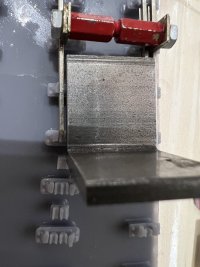
Thanks Martin and Jim (nice to meet you here Jim)

Having followed Martin's guidance I have changed the settings and run a test print. I am trying to triage three things here.....Plug Track that is doing all the things it should do (briliiantly), The S Scale standards that have been proven over the years and finally my Point....

But according to my gauges and some shim my Point check rails are now correct for the widening i need (they are following the values entered in Templot rail settings).....I just need to print the timbers and some lose key chairs.
 

Attachments

  • unnamed.jpg
    unnamed.jpg
    739.2 KB · Views: 51
_______________
message ref: 8681
@Terry Downes @Tony W

Hi Terry, Tony,

This has been driving me nuts. So I went back to first principles. Rescaled the map. Established that the best track spacing fit is actually 8ft way. Established that the best turnout fit to the branch curves is actually C-11.

I then staggered the turnouts by exactly one timber space (30") so that long square-on timbers can fit across exactly.

And the middle V-crossing turned out to be 1:5.13 and positioned exactly on one of the timbers: :)

View attachment 5276

View attachment 5275

And all nicely checked.

This is of course just luck, because this is 00-SF so it can't be expected to match the prototype very closely.

I will look at the other end of the diamond later.

cheers,

Martin.
Hi Martin, I have generated vee crossing jigs for C V-11 successfully. Is there a way of generating filling jigs for the middle vee crossings 1:5.13?
1698589706701.png
 
_______________
message ref: 8682
@James Walters @Steve_Cornford

I'm pleased to report that I have now successfully modified the BOX file format to allow for saving chair heaving data. That's potentially a lot of data -- every single chair on every template in a track plan will be able to be individually changed to any different chair if needed.

In practical terms that makes sense only for the interchangeable chairs -- S1, S1J, L1, CC, SO, SI, SC, etc. But eventually there will be multiple options for each of those, e.g. for GWR, pre-grouping chairs, etc., and for custom chairs created by users. And ultimately for flat-bottom baseplates too.

The extra data will be in XML format instead of binary. That makes it infinitely expandable as needed, at least in theory. The downside is that it requires an awful lot of typing, and it's easy to make typo mistakes which the compiler won't pick up. So lots of time and testing needed.

I've managed to keep the new BOX files both forward and backward compatible with all existing BOX files, but it will need a lot of testing before I release it. I'm always wary of messing with the file structure because I know folks have a lot of time and effort put into their Templot files and I don't want to break them.

Will be in 242a, but not for a while.

cheers,

Martin.
 
_______________
message ref: 8684
Hi Martin, I have generated vee crossing jigs for C V-11 successfully. Is there a way of generating filling jigs for the middle vee crossings 1:5.13?
@Terry Downes

Hi Terry,

Just click here and change the angle to whatever you want:


vee_jig_angle.png


Or you could copy the partial template containing the middle vee crossing into the control template.

cheers,

Martin.
 
_______________
message ref: 8686
Thanks both. its obvious now you say that. I'm just getting back into Templot development after a few months off and I must say, I'm enjoying all the feature updates. Well done Martin..... and Steve for the very useful updates, hints and ongoing forum support etc.
 
_______________
message ref: 8691
@James Walters @Steve_Cornford

I'm pleased to report that I have now successfully modified the BOX file format to allow for saving chair heaving data. That's potentially a lot of data -- every single chair on every template in a track plan will be able to be individually changed to any different chair if needed.

In practical terms that makes sense only for the interchangeable chairs -- S1, S1J, L1, CC, SO, SI, SC, etc. But eventually there will be multiple options for each of those, e.g. for GWR, pre-grouping chairs, etc., and for custom chairs created by users. And ultimately for flat-bottom baseplates too.

The extra data will be in XML format instead of binary. That makes it infinitely expandable as needed, at least in theory. The downside is that it requires an awful lot of typing, and it's easy to make typo mistakes which the compiler won't pick up. So lots of time and testing needed.

I've managed to keep the new BOX files both forward and backward compatible with all existing BOX files, but it will need a lot of testing before I release it. I'm always wary of messing with the file structure because I know folks have a lot of time and effort put into their Templot files and I don't want to break them.

Will be in 242a, but not for a while.

cheers,

Martin.
This is very exciting Martin. Chair heaving will be a real bonus. Don't overdo it though, we've all got plenty to play with for the time being. :)
 
_______________
message ref: 8702
This is very exciting Martin. Chair heaving will be a real bonus. Don't overdo it though, we've all got plenty to play with for the time being. :)

I've come to realise that at least some limited chair heaving is quite urgent. Otherwise some common formations will become a minefield of additional partial templates. In particular we need to be able to specify a CC chair where the check rail is from a different template. And for 00/EM tandems the half-bolted SI chair is needed at the 2nd switch toe to allow for the overscale switch openings. It's going to be a tricky chair to do because of the 00/EM flange depths hitting the bolt.

cheers,

Martin.
 
_______________
message ref: 8720
@James Walters

Some progress:


heave_chairs1.png


Select the timber and then click the heave chairs ... button.

The boxes change colour as a reminder if you change or omit a chair.

I have left plenty of space for more tick-boxes. :)

Each timber has a maximum of 4 chairs of its own. If it is capturing other chairs from a different template, these settings must be made on that template. Plain track has only rails 1 and 3. All switch chairs are on rails 1 and 4. All crossing chairs are on rail 3. Check rail chairs are on the adjacent running rail.

The flip key tick-box changes the direction in which the key is driven into the chair. For example adjacent to fishplates.

When I've got the slab & bracket AA chairs done they will become the default. There will be a tick-box to change back to the current cast chair where it's wanted.

Still a long way to go to get it all working, but I'm hoping I can do a release with most of it working in a few days time before James releases his video. Not specifically for this, but there are other changes in 242a which will be useful.

cheers,

Martin.
 
_______________
message ref: 8733
Brilliant, nice and simple too. I can see this unlocking a lot of creativity. CC chairs on tightly-radiused plain line for example.

I'm enjoying the PWI book you recommended by the way Martin. (y)
 
_______________
message ref: 8735
Hi Martin,
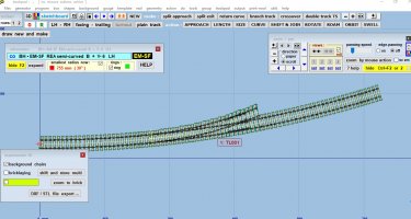
For some reason I can't get the layers to export correctly in DXF 2D format. I am not sure if it's a bug or not. Given I have done this before in 241 with no issue. So I am a bit stumped.
The box file used is in fact the start curved turnout, set to EMSF and chairs activated.
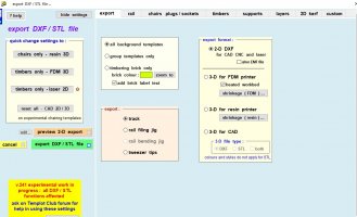
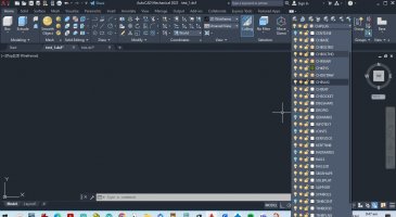
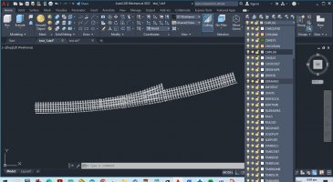
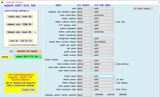
The attached screen shots show the settings I have from Templot, the two screen shots of my cad package, I have used to show what actually seems to be exports into the generated DXF file, with the "only the switch off layers you need to read it backwards IE the screen is set to zoom extents, and only the layers switched off are actually exporting anything all the layer still active actually have no data associated. In the next screen shot I have shown all layers on, IE the active layers inverted showing Templot is exports some of the data.
also of note some layers are set to black on the export setting but in fact export out as different colors.
At this point in time I am not sure the issue is with Templot or how data is exporting out of my machine. I have also tried rebuilding the Templot and exporting again no change was seen. I can send you the box file but that dose not help too much I think.
PS when I set to 2D export for laser I get nothing at all showing on the screen but some layers do show in the generated layers inside Autocad.
Cheers
Phil.
 

Attachments

  • base curved templot used.jpg
    base curved templot used.jpg
    201.4 KB · Views: 48
  • 2D Kerf settings.jpg
    2D Kerf settings.jpg
    93.5 KB · Views: 49
  • export settings.jpg
    export settings.jpg
    131.7 KB · Views: 51
  • only the switch off layers are actually exporting.jpg
    only the switch off layers are actually exporting.jpg
    153.7 KB · Views: 44
  • all layers switch on.jpg
    all layers switch on.jpg
    198.2 KB · Views: 51
  • V241 all layers outputting.jpg
    V241 all layers outputting.jpg
    170.9 KB · Views: 51
_______________
message ref: 8736
CC chairs on sharp plain line for example
@James Walters

Hi James,

You can already do that:

cont_check_chairs.png


Search continuous check rail -- essentially it is done as approach track on a turnout template which is then shortened back to hide the turnout part. Adjust the length of the check rail back through the switch into the approach.

p.s. see my notes for Michael about widening the check rail gap.

cheers,

Martin.
 
_______________
message ref: 8738
@James Walters

Hi James,

You can already do that:

View attachment 7523


Search continuous check rail -- essentially it is done as approach track on a turnout template which is then shortened back to hide the turnout part. Adjust the length of the check rail back through the switch into the approach.

cheers,

Martin.
Thanks Martin,

I should have known that. Everyday is a school day with Templot. 👨‍🎓
 
_______________
message ref: 8739
Hi Phil,
So I have started Templot, set gauge to EM-SF, then switched on experimental chairing.
Then stored the control template.
Then clicked export.
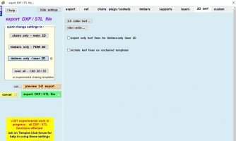
Then clicked on timbers only - laser 2d
1698787453034.png


then invoked the preview 2-d export ( and on my computer I am using Inkscape as the .DFX viewer) and I get this:-
1698787530446.png


which what I would expect.
A reduced number of layers but only the KERFSOCK and KERFTIMB have any objects in them.
If i flip back into Templot and show the export settings & go to layer I get this :-
1698787646720.png


which is exactly what I would expect.
Steve
 
_______________
message ref: 8740
Last edited:
Hi Martin,
For some reason I can't get the layers to export correctly in DXF 2D format. I am not sure if it's a bug or not. Given I have done this before in 241 with no issue. So I am a bit stumped.
The box file used is in fact the start curved turnout, set to EMSF and chairs activated.
The attached screen shots show the settings I have from Templot, the two screen shots of my cad package, I have used to show what actually seems to be exports into the generated DXF file, with the "only the switch off layers you need to read it backwards IE the screen is set to zoom extents, and only the layers switched off are actually exporting anything all the layer still active actually have no data associated. In the next screen shot I have shown all layers on, IE the active layers inverted showing Templot is exports some of the data.
also of note some layers are set to black on the export setting but in fact export out as different colors.
At this point in time I am not sure the issue is with Templot or how data is exporting out of my machine. I have also tried rebuilding the Templot and exporting again no change was seen. I can send you the box file but that dose not help too much I think.
PS when I set to 2D export for laser I get nothing at all showing on the screen but some layers do show in the generated layers inside Autocad.
Cheers
Phil.
@Phil G

Hi Phil,

I can't really follow what you are saying. Please can you post your DXF file? I will open it in TurboCAD and see what's happening. I don't know anything about AutoCAD. It seems to be working ok for Steve. Thanks.

cheers,

Martin.
 
_______________
message ref: 8743
@Phil G

Hi Phil,

I can't really follow what you are saying. Please can you post your DXF file? I will open it in TurboCAD and see what's happening. I don't know anything about AutoCAD. It seems to be working ok for Steve. Thanks.

cheers,

Martin.
Hi Martin,
I have to go out for about an hour will post box and DXF file when I get back
cheers
Phil,
 
_______________
message ref: 8744
@Steve_Cornford

Hi Steve,

Thanks for helping. I think you posted the same screenshot twice in your last post.

cheers,

Martin.
 
_______________
message ref: 8745
Hi Martin,
I have to go out for about an hour will post box and DXF file when I get back
cheers
Phil,
Hi Martin,
please find attached 5 DXF files, and the box file, all have changes is the layers setting, IE,
test,
is all layers set to black(white on cad screen) except kerf socket and kerf Timber outline both set to yellow but not exporting to my cad.
test-1
is set to the same but with 2D laser only with export only kerf lines unticked
test_2 is the same settings with export only kerf lines ticked
test_3
is a full reset to export all layers (IE the colours should change some do and some don't. with export only kerf lines unticked
on all four tests what I am missing is the kerf sockets and kerf timbers out layers. there is a layer called that but no data by the looks of it.
test_4 is the same as test_3 but with export only kerf lines ticked.
so on my export ticking the export only kerf lines see s to have no effect.
on all the exports the kerf layers are exported as layers within the DXF file but nothing seems to be on the layer visually.
E.G its creating a layer name but there seems to be no data attributed to these layers

I have just downloaded Inkscape and on face value IE just a quick visual check I seem to be getting the same results.
cheers
Phil,
 

Attachments

  • test.dxf
    130.1 KB · Views: 39
  • test_2.dxf
    30.1 KB · Views: 41
  • test_3.dxf
    129.9 KB · Views: 38
  • test_4.dxf
    129.9 KB · Views: 39
  • Box_test.box
    20.7 KB · Views: 43
  • test_1.dxf
    2.2 KB · Views: 39
_______________
message ref: 8755
You seem to have set most of the colours to black on your layers.
Hi Steve,
yes that's correct I set all layers to black (showing white on the cad)except the kerf layers these were set to yellow. the idea was to make it easy to see what was and what was not exporting.
I have also tried both ticking and unticking the export kerf lines only which seems to have no obvious change at all.
PS just downloaded Inkscape and on my laptop I am getting the same results as on the CAD. I am only checking the cad as a precursor to exporting in Lightburn. All are showing the same issue for me on my laptop.
cheers
Phil
 
_______________
message ref: 8756
@Phil G

Hi Phil,

Thanks for the files. They are all entirely normal and as expected.

The reason you are not seeing what you want is that the the background template you are exporting has not been set for experimental chairing. It's always worth moving the control template out of the way so that you can see what you will be getting:


phil_box.png


You forgot to store the control template before exporting the DXF. Also, unless you need the unchaired one in a 2D DXF you probably want to delete it. You certainly don't want the two templates overlapping.

You could have had the kerf outlines for the timbers (but not the sockets) on the unchaired template if you had ticked the lower box here (on the 2D kerf tab):

phil_kerf_options.png


Also if you had not unticked the upper box you would have got only the kerf lines and nothing else, which is probably what you want for laser-cutting. But I don't know what you want for laser-cutting, so nor does Templot. You have to make your own settings. :)

cheers,

Martin.
 
_______________
message ref: 8757
I was just about to post the same. I opened the .box file, moved the control template and saw the same thing.

I've made the same mistake lots of times myself. It's easily done. :)
1698803067894.png
 
_______________
message ref: 8758
I've made the same mistake lots of times myself. It's easily done. :)
@James Walters @Phil G

Hi James, Phil,

The problem is that word experimental again. :) Too many folks are assuming that everything is finished and ready-to-use, which it isn't. This is STILL a great big experiment. Nothing is finished or as it will be when it IS finished. When that day comes, Templot will tell you that you are trying to do something which doesn't make sense. But I can't do all that idiot-proofing yet. I just can't. Too much is still likely to change.

Everyone is welcome to try plug track, but they just have to accept that at present you are picking your way through a building site.

cheers,

Martin.
 
_______________
message ref: 8759
I don't see it as a problem Martin. After I'd done it for the umpteenth time I finally learned to remember to store things in the box. That particular learning process has helped me to understand how it all works, and get my head around building things like tandems and scissors crossings.
Hopefully what Phil has posted will serve as a useful reminder to us all to 'store' before moving on.
You'll never program out the numpty-factor - at least not as far as this particular numpty goes. :)

edit: to be clear I was referring to myself as the numpty.
 
_______________
message ref: 8760
@James Walters

Hi James,

Sorry I was a bit tetchy. I'm right now adding a warning message. If you have clicked any of these:

dxf_3d_butons.png


and Templot then finds that there are no chaired templates selected for export, it will put up a message saying so.

cheers,

Martin.
 
_______________
message ref: 8761
Hi Phil,
I would recomend that you store your templates with the colour box ticked on the 3D window, and also the "timbering brick" option, and get used to the concept of changing the CB colour for different bricks.
If you then view the  box and list templates you can see that you have got bricks & what colour they are stored with.
Eve n with laser cutting this is a useful way of grouping templates into bricks ( DXF files)
Steve
 
_______________
message ref: 8763
Hi Phil,
The reason the  KERFSOCK is a different colour to the  KERFTIMB layer is that you need to instruct your laser to cut the KERFSOCK layer first, thus ensuring they are in the right place, before cutting the KERFTIMB layer.
Doing it the other way round or cutting them together will result I imprecise positioning of the sockets within the timbers.

What thickness of ply have you managed to source in NZ?

Steve
 
_______________
message ref: 8764
What thickness of ply have you managed to source in NZ?
Hi Steve,
just getting over how stupid I feel. I win numpty of the year for sure.

Thanks for the input makes sense, to answer you question I have both 2 and 3 mm ply, I have just got my laser up and running.
well it will be when I cut something, :) state of play so far is I have made a special portable covered 1200 x 900 work table complete with 5 side plus base cover, making it fully enclosed and light proof, this has 6 x exhaust fans and 1 x fresh air input fan, the exhaust is temperature monitored complete with over temp alarm system. the exhaust goes to a carbon filter, to hopefully clean and scrub the fumes.
I think there area going to be quite a few questions about kerf lines in the next few days. maybe even latter today.
Not sure I will stick 100% to Templot alone at this stage especially after what I managed earlier today my time !!!!
I think I may just make up some brick clips on the outside of each plate section.
cheers
Phil
 
_______________
message ref: 8770
Hi Martin and James
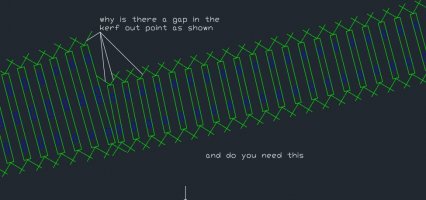
Are you able to tell me why the kerf break out lines have gaps in them as per the attached. I know there will be a reason just need to understand.
cheers
Phil
 

Attachments

  • question about gap in kerf run out.jpg
    question about gap in kerf run out.jpg
    92.4 KB · Views: 48
_______________
message ref: 8773
Hi Martin and James
Are you able to tell me why the kerf break out lines have gaps in them as per the attached. I know there will be a reason just need to understand.
cheers
Phil
@Phil G @James Walters

Hi Phil,

Those diagonal lines are called snibs. If there is a gap in them (it's your choice in the settings), it is to prevent the waste from between the timbers falling free while laser cutting.

If you search snibs there was a long discussion with James about this stuff about a year ago. The settings are at:


nibs_snibs_button.png


The gaps are called the snib space and if set to zero they won't exist. You can set each one independently. The compass indications refer to the timber, not the space between the timbers.

The nibs are the short pieces at the centre of the timber end to retain it. You can switch them off too.

No doubt James will be explaining all this in his videos, and the optimum settings he has found for use. I know nothing. :)

p.s. none of these settings are yet included in the saved settings, so you need to enter them each time.

cheers,

Martin.
 
_______________
message ref: 8774
HI Phil,

Nothing to add to Martins post above, save to mention the settings which I've been using.

I set the nib width and length to 0.6mm (this would be a handy new default Martin). I've found this to be a good compromise between ease of removal and timbers not falling out of the fret due to handling.

If you want the waste between timbers to fall out set the snib spaces to 0.

1698832601651.png


To retain the waste, set the snib spaces to something like this, it's best to experiment with the material you are using:

1698832696477.png


I have found it useful sometimes to engrave a label onto the waste pieces to remind me of what I was thinking when I produced the template.

Once in Lightburn, drag a quick rectangle around the shape to release your template from the sheet.

1698833006891.png


Speed/Power settings will be machine & material specific and require some experimentation to get the best results. Air assist will be help keep a cleaner cut.
 
_______________
message ref: 8775
Hi @James@Martin,
Thanks, all make perfect sense.
The attached screenshot is where I got a bit confused.

result of a crossing.jpg


good info on Lightburn much appreciated.
Yes I do have air assist 27 lts min
I have a 10 watt output diode and a friend has lent me his 5 watt laser, which I think will be under powered. I have also been in contact with the laser manufacture, and for 3 mm ply there recommending a 20 watt or even a 30 watt diode. There is a big price increase as you step up in power, so I am hoping 20 w will do the job.
I am not sure 10 watts will be enough to get good stable results IE likely will need two pass or too slow a speed thus getting too much over burn, but there is only one way to find out.
I will send you a DM with my crossover DXF once its finished, if you could just give me your thoughts on my snibs in a tight space.
PS sockets are only in yellow so I can see them easy at this stage.
cheers
Phil,
 
_______________
message ref: 8776
@Phil G @James Walters

Hi Phil,

To prevent snib conflicts between templates, reduce these settings:

snib_extents.png


The first dimension is the position of the gaps from the timber.

The second dimension is the overall length of the snibs.

At present these nib/snib settings are global for all templates, which obviously isn't entirely convenient.

I'm intending to make them template-specific, so that each template can have its own settings, on each side of the template. I mentioned this yesterday in relation to the waybeams.

But I need a chance to draw breath. There is so much still to do and I can't do it all at once.

cheers,

Martin.
 
_______________
message ref: 8778
Back
Top