Templot Club forums powered for Martin Wynne by XenForo :

TEMPLOT 3D PLUG TRACK - To get up to speed with this experimental project click here.   To watch an introductory video click here.   See the User Guide at Bexhill West.

  • The Plug Track functions are experimental and still being developed. Some of the earlier pages of this topic are now out-of-date.

    For an updated overview of this project see this topic.   For some practical modelling aspects of using Plug Track see Building 3D Track.

    The assumption is that you have your own machines on which to experiment, or helpful friends with machines. Please do not send Templot files to commercial laser cutting or 3D printing firms while this project is still experimental, because the results are unpredictable and possibly wasteful.

    Some pages of this and other topics include contributions from members who are creating and posting their own CAD designs for 3D printing and laser-cutting. Do not confuse them with Templot's own exported CAD files. All files derived from Templot are © Martin Wynne.
  • The Plug Track functions are experimental and still being developed.

    For an updated overview of this project see this topic.   For some practical modelling aspects of using Plug Track see Building 3D Track.

    The assumption is that you have your own machines on which to experiment, or helpful friends with machines. Please do not send Templot files to commercial laser cutting or 3D printing firms while this project is still experimental, because the results are unpredictable and possibly wasteful.

    Some pages of this and other topics include contributions from members who are creating and posting their own CAD designs for 3D printing and laser-cutting. Do not confuse them with Templot's own exported CAD files. All files derived from Templot are © Martin Wynne.

Experimental 3D plug track - up to version 244c

Quick reply >
@Phil G @James Walters

Hi Phil,

To prevent snib conflicts between templates, reduce these settings:

View attachment 7579

The first dimension is the position of the gaps from the timber.

The second dimension is the overall length of the snibs.

At present these nib/snib settings are global for all templates, which obviously isn't entirely convenient.

I'm intending to make them template-specific, so that each template can have its own settings, on each side of the template. I mentioned this yesterday in relation to the waybeams.

But I need a chance to draw breath. There is so much still to do and I can't do it all at once.

cheers,

Martin.
Hi Martin,
Thanks, the dims make sense now, I would not worry too much about doing much more with nibs and snibs in Templot at this time. that's one field we can do outside of Templot and once we have the key data we can feed it back to you. James clearly understands his co2 laser, once I get into the swing of it I am happy to feed back input on diode lasers.
cheers
Phil
 
_______________
message ref: 8779
Hi @James@Martin,
Thanks, all make perfect sense.
The attached screenshot is where I got a bit confused.

View attachment 7577

good info on Lightburn much appreciated.
Yes I do have air assist 27 lts min
I have a 10 watt output diode and a friend has lent me his 5 watt laser, which I think will be under powered. I have also been in contact with the laser manufacture, and for 3 mm ply there recommending a 20 watt or even a 30 watt diode. There is a big price increase as you step up in power, so I am hoping 20 w will do the job.
I am not sure 10 watts will be enough to get good stable results IE likely will need two pass or too slow a speed thus getting too much over burn, but there is only one way to find out.
I will send you a DM with my crossover DXF once its finished, if you could just give me your thoughts on my snibs in a tight space.
PS sockets are only in yellow so I can see them easy at this stage.
cheers
Phil,
Phil
I have been cutting sleepers from 3mm plywood with a 22w laser - works very well. This is in O-MF too, so a whole lot chunkier than some! The snibs and nibs work exceedingly well. I leave them on default settings and, once cut, the sleepers can either be placed on the layout surface as a "brick" or snapped out for individual placement and fettling.

Davey
 
_______________
message ref: 8780
I have been cutting sleepers from 3mm plywood with a 22w laser - works very well.
Hi Davey,
That's great news here in NZ its about 580 dollar for a 20W as you say its actually closer to 22W and then 1100 dollars for a 30W there is talk of a 40W being released round about X-mass but that is even more expensive. rumour is about 2K
cheers
Phil
 
_______________
message ref: 8783
Hi Phil,
What are you planning to use as a trackbed?
Steve
Not sure yet, hoping to try pocketing cork so it doubles as a template, and a sound absorbing base layer as well.
That way I think I can get clip fit chairs, with two mm ply timbers and 3 mm cork, inset ideally about 1.5 mm or so.
cheers
Phil,
 
_______________
message ref: 8784
Pocketing the cork to a fixed depth is likely to be slow, smoky, and very dirty. I have tried it and the results were discouraging.
Would a cut straight through the cork not be a quicker/cleaner alternative? I can't see the need for shallow pockets, unless I'm missing something?
 
_______________
message ref: 8785
Hi Martin et al,
Just though I would point out that if you start with a turnout with experimental chairing switched on and the experimental 3D window set as follows:-
1698838639404.png

when you then use any of the make options on the tools menu it does not set any of the stored to templates to bricks.
1698838912639.png

However, all you have to do is tick the brick tick box on the box screen for each template and bobs your uncle.
Steve
 
_______________
message ref: 8787
...

Once in Lightburn, drag a quick rectangle around the shape to release your template from the sheet.

View attachment 7573

Speed/Power settings will be machine & material specific and require some experimentation to get the best results. Air assist will be help keep a cleaner cut.

@James Walters @Phil G

Hi James, Phil,

You can add that rectangle in the DXF if more convenient (or several of them). Just draw a rectangle in the background shapes in the usual way as for a chair raft. In 2D exports they get exported as-is:


dxf_2d_shapes_tc.png


Switch on the background shapes layer:


dxf_2d_shapes.png


The end nibs tick-box switches off the nibs and snibs entirely. That should have been moved to the 2D kerf tab, and I will do that right now before I forget.

cheers,

Martin.
 
_______________
message ref: 8790
Hi Martin et al,
Just though I would point out that if you start with a turnout with experimental chairing switched on and the experimental 3D window set as follows:-
View attachment 7583
when you then use any of the make options on the tools menu it does not set any of the stored to templates to bricks.
View attachment 7584

However, all you have to do is tick the brick tick box on the box screen for each template and bobs your uncle.
Steve
@Steve_Cornford

Hi Steve,

I've been in two minds about changing that because the intention is not to do track design work with the chairing switched on. Otherwise the screen response will get very slow. As with shoving timbers, adding the chairing is a task to be done when the track design is finished. Otherwise you are likely to waste a lot of time re-doing stuff, especially where chairs are being captured on long timbers.

The make tools do however set the marker colour (if the box is ticked), which is useful if you are using marker colours as part of the layout design. The colour panel ought not to be under "experimental 3D", it should be somewhere else.

The "bricklaying" setting is intended to come into play only when you are extracting the timbering bricks from the track plan, which is done by copying and storing rather than using the make tools.

But there is a lot of learning still to do about the best way of approaching all this. For a small shunting plank layout you could actually design it in timbering bricks instead of full templates if you wished. For a large main-line layout that would be a nightmare -- design it first, bricks later.

cheers,

Martin.
 
_______________
message ref: 8792
_______________
message ref: 8793
the A ( or isit AA) chair
@Steve_Cornford

Hi Steve,

It's the A chair on the prototype and the AA chair in Templot.

On the prototype the chairs are designated by their position in sequence and there is only one of each in order -- X , A , B , C , ... That means the C chair on a 1:5 crossing say, is not the same type of chair as the C chair on a 1:14 crossing.

In Templot the chairs are designated by the type of chair, and there may be more than one of each type, depending on the crossing angle. For example the BB chair is always the one carrying the flare ends on the wing rails. It may or may not come right after the AA chair depending on the crossing angle. On longer crossings there will be another one in between, called the AB chair. Or even several AB chairs. (But if there are several of one type they won't be interchangeable.)

On the prototype they would be simply A , B, C for say 1:16 without regard to the fact that a 16C chair looks nothing like a 5C chair.

Templot does it differently so that it can generate a set of chairs for any crossing angle, including non-standard angles such as 1:8.35

At present the Templot chair types are not shown anywhere on the templates or the chair rafts, but they will be identified eventually. You will be able to print out a paper chart showing which is which for any template. This will be necessary when we reach the stage that you can enter your own custom chair designs for different prototypes.

cheers,

Martin.
 
_______________
message ref: 8772
.
Another day, another tick-box: :)

View attachment 7375

...

0.5mm dia. (25swg, 24awg) plain tinned copper wire is very suitable for this and is easy to bend and fit:

Can you provide options for different wire sizes? 24 SWG might be too current-limiting for some people in 4mm scale. I'd think that allowing for 22 and 20 SWG would be useful. (Possibly larger for larger scales)
 
_______________
message ref: 8810
Can you provide options for different wire sizes? 24 SWG might be too current-limiting for some people in 4mm scale. I'd think that allowing for 22 and 20 SWG would be useful. (Possibly larger for larger scales)
@genixia

Hi,

Sure:

wire_ridge_dims1.png


wire_ridge_dims.png


I hardly ever add anything in Templot which can't be adjusted. I've learned over the years that will be the very first question. If Templot could generate a tea trolley I would make sure it could be changed to a combine harvester with a couple of clicks. :)

But I'm a bit mystified what locomotive you would be running in 4mm/ft scale which would draw 10 amps or more? I would very likely use a thinner wire if it was simply an electrical connection, but in this case it is also intended to provide a physical restraint on the rail to prevent it sliding more than a few thou out of position in the chairs. But with sufficient freedom to allow for thermal expansion/contraction.

cheers,

Martin.
 
_______________
message ref: 8812
.
Another day, another tick-box.

This one is just for convenience. You can switch the chairing on (or off) immediately when starting a fresh template:


mint_chairing.png


I'm keeping the word "experimental" on there, at least until I have the K-crossings done -- it's my get-out-of-jail card when things go wrong. :)

cheers,

Martin.
 
_______________
message ref: 8823
@James Walters

Tick-box of the day. :)

I noticed in the video that James was unsure about how much to shrink the gauge for a raft of S1 chairs. Also he didn't store the first template before the multi run, which means he ended up with 13 chairs in the row instead of the 14 which fit conveniently across the build plate on the Alkaid printer.

So I have made a few changes. To save resin, and space on the build plate:

1. This function is changed from "shift and store" to "store and shift" which means you don't store the first one yourself. Definitely not, otherwise you will get a duplicated template and that will upset the mesh fixing for sure.

2. I have added a tick-box shrink gauge multi which causes the gauge to shrink automatically, and be restored afterwards. At the same time the timbers get shortened -- they don't get printed so need not be on the screen at all, but the shortened outlines make a convenient guide for drawing the raft rectangle. I haven't automated the rectangle because I have some further ideas and changes for that in due course.


store_shift_shrink.png


store_shift_raft.png


This works for plain track templates only. They should have been shortened to a single sleeper, and shifted to a clear area of the trackpad, before clicking the store and shift multi button.

edit: now works on any of the first 3 timbers of a turnout too. For P slide chairs, CC, CCL, CCR.

For S1J chairs instead of S1, change the end sleeper width to 12" in the timbering data.

For L1 chairs, click the menu item for all L1 chairs.

For turnout templates, for P slide chairs and CC check chairs it is still necessary to create the partial templates manually for bulk printing. I will prepare a suitable BOX file and post it soon to make it easier.

The default shrunk gauge produces a space of 4" scale between the chairs. This can be adjusted in the raft settings if desired.

cheers,

Martin.
 
_______________
message ref: 8852
That's a great little addition. Really neat. :)
@James Walters

Thanks James.

For the loose jaws I will do something a bit different, not sure what yet. They could be packed a lot tighter on the rafts. S1 and S1J chairs share the same loose jaw, but not for L1.

p.s. you are up to 760 views, and the first day is still young! Is anyone betting on how many after a week? :)

Martin.
 
_______________
message ref: 8854
I'm looking forward to seeing how You are going to achieve 'bunched' chairs for turnouts.
@Terry Downes

Hi Terry,

My plan is not to try -- it could lead to lots of problems in identifying which chair goes where in the timbers.

Instead my thought is to fill wasted space on the raft between the crossing chairs with extra S1 chairs. There is always a need for those. If we use a taller support pyramid for the crossing chairs than for the S1 chairs, it should be easy to spot the crossing chairs on the raft.

But it's just ideas at present. One thing at a time -- the next thing is lunch. :)

Martin.
 
_______________
message ref: 8857
Hi Martin,
As I watched James video it struck me there is room for some automation of (common type chairs) ready to print them low and behold you have already done it. well done.
By the way I very much like your idea on turnout chairs, they also really need the loose jaws (when selected to be on the same raft given there in some cases going to be unique to there chairs.
cheers
Phil
 
_______________
message ref: 8876
I have just finished watching James's video and the count is 3.3k views.

James, looking forward to the next instalment.
 
_______________
message ref: 8888
Hi James,
Just a quick question/comment on your video, which I have to say was brilliant. re the Cura settings for the FDM printer.
Martin often mentions the ironing feature, which I believe, and I am no expert on Cura settings is something you have to manually turn on.
It's very likely the FDM timber section Martin gave you for S4rum, which i believe you show in the video, will have been made with ironing switch on.

So if and when people try to make the bases if they don't turn this feature on there FDM timber bases will not look as good.
With Martin being out of action for sometime, does anybody else understand the ironing feature correctly and how to apply it to timber bricks?
IF so I think a comment on this would be wise to make for the video.
Cheers Phil
PS I am going up my bid on the views and say its quickly going to me your most viewed Bexhill west video (which will be impressive given your well over 7.5K on quite a few of them.
 
_______________
message ref: 8890
Hi Phil,
I'm going to look at the FDM setting in a little more detail in Part 2 : Turnouts.

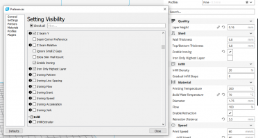
The ironing feature is simple to turn on, screenshot below.

It is possible to iron every layer, or just the highest layer, and like Templot, Cura offers lots of variables to play with.
If we follow Martin's advice and wet sand the topmost surface of the timbering bases, then I'm not convinced that ironing is essential, although it undoubtedly produces a nicer finish, and if one is in no rush it doesn't hurt to enable it.
But it's ultimate quality will depend upon other profile settings. Personally, I'm finding that experimentation with the retract settings in Cura is worthwhile, but I suspect that the precise settings to achieve perfection may be machine specific.

Have a play would be my advice.

I'm sure Martin will offer better advice upon his return as I know he's put a lot of time into the specifics of Plug Track printing, whereas my own experience is more general.
Let's hope he's match-fit again very soon, and back here when (and only when) he's feeling up to it.

Cheers,

James

1699212412219.png


p.s. to be clear, I'm not presenting these settings a optimal, just they are what I've been playing with at the moment.
 

Attachments

  • 1699210787750.png
    1699210787750.png
    118.5 KB · Views: 45
_______________
message ref: 8891
Last edited:
But it's ultimate quality will depend upon other profile settings. Personally, I'm finding that experimentation with the retract settings in Cura is worthwhile

Hi James

Good to know your on to it, I guess my concern is not accidently discouraging to many people away from plug track, that said if you already have an FDM printer (or six in some peoples case) :) your already across the more fine tuning the better your results concept.

I agree with what you have said about settings, especially the much more aggressive retracts to minimise stringing. the downside to using a Bowden tube set up, is it does not handle aggressive retracts anywhere nearly as good as a direct drive extruder.
cheers
Phil,
 
_______________
message ref: 8892
Hi all,

Wishing Martin well .......

A while ago Martin posted a prototype picture of the switch blades meeting the running rail and in particular how the running rail was shaped to accomodate the blade...

But I cannot find the picture - looked all over this site.....can anyone else remember it? - was I dreaming? - or did I see it somehere else?

Michael
 
_______________
message ref: 8911
Back
Top