Templot Club forums powered for Martin Wynne by XenForo :

TEMPLOT 3D PLUG TRACK - To get up to speed with this experimental project click here.   To watch an introductory video click here.   See the User Guide at Bexhill West.

  • The Plug Track functions are experimental and still being developed. Some of the earlier pages of this topic are now out-of-date.

    For an updated overview of this project see this topic.   For some practical modelling aspects of using Plug Track see Building 3D Track.

    The assumption is that you have your own machines on which to experiment, or helpful friends with machines. Please do not send Templot files to commercial laser cutting or 3D printing firms while this project is still experimental, because the results are unpredictable and possibly wasteful.

    Some pages of this and other topics include contributions from members who are creating and posting their own CAD designs for 3D printing and laser-cutting. Do not confuse them with Templot's own exported CAD files. All files derived from Templot are © Martin Wynne.
  • The Plug Track functions are experimental and still being developed.

    For an updated overview of this project see this topic.   For some practical modelling aspects of using Plug Track see Building 3D Track.

    The assumption is that you have your own machines on which to experiment, or helpful friends with machines. Please do not send Templot files to commercial laser cutting or 3D printing firms while this project is still experimental, because the results are unpredictable and possibly wasteful.

    Some pages of this and other topics include contributions from members who are creating and posting their own CAD designs for 3D printing and laser-cutting. Do not confuse them with Templot's own exported CAD files. All files derived from Templot are © Martin Wynne.

Experimental 3D plug track - up to version 244c

Quick reply >
@Michael Woods

Hi Michael,

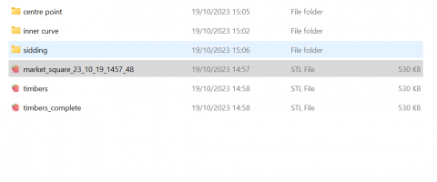
That's a puzzle if you have tried different file names. What sort of STL file is it -- for chairs, loose jaws, timbers, both? How many templates in the file?

What happens if you try creating both DXF and STL:

dxf_both.png


You will find the STL file in the DXF-FILES folder, not in STL-FILES. You will need to open it manually in 3D Builder for mesh-fixing if you use 3D Builder.

As you can see from the reference to floppy disks, it is many years since I have looked at the error handling in the DXF file functions. I need to have a fresh look at that. But if it has been working fine until now it must be something on your computer rather than in Templot.

But please post your BOX file -- there may be something odd in it which is affecting the STL file. I will see if I can create an STL file here.

cheers,

Martin.
 
_______________
message ref: 8480
Martin - I have worked out what it is .......

On Sunday within SDL RAW I created three sub folders (see attachment)

I can save any Templot STL file name to the SDL RAW root directory

I can save any Templot STL file name to "siding"

But what seems to be happening on my computer is that if I try and save a file to "inner curve" Templot does not like the space between inner and curve. (error message)

Then it appears that I cannot save the file anywhere else - for example if I try and save back in STL RAW (error message)

The solution is easy I will add an underscore between words in my directory names....


1697724714151.png
 

Attachments

  • 1697724507515.png
    1697724507515.png
    26 KB · Views: 47
_______________
message ref: 8481
@Michael Woods

Hi Michael,

BINGO!

For years and years I have been saying over and over again on forums and web sites not to use spaces in file names, folder names, web page links, etc. For a long time in the last century it was a given not to do that. Then over the years operating systems added various kludges to make it work, but it can still come back to bite you occasionally. Especially in Templot, where the compiler dates from 1998! :(

Glad you got it fixed. :)

cheers,

Martin.
 
_______________
message ref: 8482
@Michael Woods

Hi Michael,

BINGO!

For years and years I have been saying over and over again on forums and web sites not to use spaces in file names, folder names, web page links, etc. For a long time in the last century it was a given not to do that. Then over the years operating systems added various kludges to make it work, but it can still come back to bite you occasionally. Especially in Templot, where the compiler dates from 1998! :(

Glad you got it fixed. :)

cheers,

Martin.
Thanks Martin - I have not been using Templot for years so will excuse myself on this one...... :) but makes sense!
 
_______________
message ref: 8483
_______________
message ref: 8514
.
Another day, another tick-box: :)

dropper_ridge1.png


After assembly of plug track the rails are free enough to slide through the chairs if pushed. This is no bad thing -- it allows for some thermal expansion/contraction and proves the chairs are not stressed (which might lead to stress-cracking over time).

But we don't want the rails to creep more than a few thou out of position. They need to be sufficiently locked to the timbering base to ensure they remain in the correct alignment with each other -- for example the set in the turnout-side stock rail needs to be aligned with the toe of the switch blades.

All the rails will need at least one dropper wire electrical connection, which might conveniently be arranged to provide just the right amount of movement restraint on the rail. Free to flex a fraction but not to move significantly out of place.

Plug track allows the dropper wires to be neatly attached to the underside of the rail before assembly, and there is space for them to be bent over to run horizontally between the timbers to the side of the track. This means the layout connections can be made above board, for example to a brass pin or tag at the side of the track. It all gets hidden under the ballast.

0.5mm dia. (25swg, 24awg) plain tinned copper wire is very suitable for this and is easy to bend and fit:

https://uk.rs-online.com/web/p/copper-wire/0390549

A typical turnout will need 10 dropper connections -- it's worth having live check rails for improved pickup and running.

0.5mm tinned copper wire is also available as 15amp fuse wire. But it's an expensive way to buy it on a card. Beware some cheap fuse wire is aluminium, not tinned copper.

To attach it to the timbers to prevent rail movement I have added a ridge along the timber flanges, leaving a 0.5mm angled groove behind it:


dropper_ridge3.png


The dropper wire can be pressed down into this groove after the rail is in position, and if necessary retained with some suitable sealant*.

Here is my provisional jig for soldering dropper wires to the underside of rail. As you can see no expense has been spared:

dropper_jig1.jpg


dropper_jig2.jpg


Four 2p coins glued to a bit of wood with a gap between them for the rail. A 1p coin glued on top to support the dropper wire. A blob of Blu-Tack to stop the rail sliding, and another blob to hold the wire while it is soldered. The ink marks on the rail show the chair positions which must be avoided, and also confirm you have the rail upside down.

It works fine, but I'm intending to create a proper resin-printed equivalent (and include the file in Templot, adjustable for scale and rail section).

*I suggest old enamel paint from a 25-year-old tinlet of Humbrol as a sealant, -- or children's modelling clay from the pound shop. This handy stuff looks and feels like brightly coloured Blu-Tack, with the difference that if left for a few days it loses its stickiness and dries out to a flexible blob of rubbery material. Which is ideal for sealing things but can be removed easily if necessary.

Martin.
 
_______________
message ref: 8516
Attach files
This means the layout connections can be made above board, for example to a brass pin or tag. It all gets hidden under the ballast.
Hi Martin,
More out of curiosity to be honest, is there a reason you don't seem to like dropper wires going below the baseboard?
Obviously on face value its a bit easier, but given most modellers now use under mounted servo motors, to switch turnout blades for example. The under base boards is probably more alive now than ever.
Only asking as all this wire bending into ridges seems like a lot of work to me, and I was wondering if I had missed something.

IE are you saying the dropper wire is now bifunctional, 1 to hold rails in place, and 2 to supply power to the rails.
cheers
Phil
 
_______________
message ref: 8519
More out of curiosity to be honest, is there a reason you don't seem to like dropper wires going below the baseboard?
@Phil G

Hi Phil,

On a permanent layout working below the baseboard means bending down in the dark, or with a torch or headlight, struggling to see what you are doing, bobbing up and down to get the right screwdriver, knocking over your cup of coffee, getting solder in your eye, twisting your knee, etc. No fun at all.

On a portable layout individual boards can be turned over or stood vertical, but that's a lot of faff unbolting and dismantling every time you need to make a simple change or adjustment, and risks damage to the track and scenics.

If everything is on top, it is just so much more enjoyable to work in comfort with everything to hand and plenty of light. But that's just me, each to his own.

But when it comes to dropper wires specifically, very definitely I don't want them dropping vertically below the track. That means in practice that they can't be added until the track is finished and laid. That was fine in the days of soldered copper-clad track, but now that track is a finely detailed scale model with delicate components, the last thing you want is to be drilling the baseboard through it, or hovering near plastic components with a soldering iron while reaching across a baseboard -- especially when it's difficult to make a neat job of attaching dropper wires in situ (unless you remembered to drill holes through the rail before assembly -- which is more work).

Also, adding dropper wires below the track makes it difficult to lift and re-use it. Self-contained droppers running to the side of the track make that much easier, and they also make it easy to test the track under power while it is under construction on the bench.

The great advantage of plug track with deep timbers is that dropper wires can be invisibly attached to the underside of the rail before assembly and run to side of the track clear of the work. By all means drill a hole there and connect the dropper tails to wires from below if you prefer not to have the layout interconnections above board. But not under the track!

For point motors I'm intending to have a dummy tie-bar slider between the toe timbers -- the guide ribs are already done. So no need for gaping holes under the switch drive either. Using low-friction golden rods the drive can be taken to a point motor hidden in a signal box, under a barn on the hillside, behind a removable backscene, etc. All on top and easily accessible in the event anything needs attention.

IE are you saying the dropper wire is now bifunctional, 1 to hold rails in place, and 2 to supply power to the rails.

Well yes, if you wish. It's not essential, the rails can be locked in place with superglue or epoxy on a couple of chairs if you prefer. But since a dropper wire is needed anyway, using it to restrain the rail invisibly seems worth doing. It has the advantage that copper wire is soft and ductile, so allowing the rail a little bit of freedom for thermal expansion/contraction without stressing the chairs.

cheers,

Martin.
 
_______________
message ref: 8520
Well yes, if you wish. It's not essential, the rails can be locked in place with superglue or epoxy on a couple of chairs if you prefer. But since a dropper wire is needed anyway, using it to restrain the rail invisibly seems worth doing. It has the advantage that copper wire is soft and ductile, so allowing the rail a little bit of freedom for thermal expansion/contraction without stressing the chairs.
@Phil G

Hi Phil,

This shows how a dropper wire can be used to limit the freedom of the rail to slide out of position:
dropper_ridge4.png


The ridge along the timber flanges is back-angled so that a 0.5mm bare dropper wire can be clipped down behind it with a thin-bladed screwdriver, as it runs across to the side of the track where it connects with the main layout wiring. It is retained quite firmly, but some additional sealant could be added if desired.

The soft copper wire has just enough give in it to allow the rail a little freedom to shift through the chairs with temperature changes.

There are two grooves available per timber space, so with a little pre-planning of the dropper positions it should be possible to accommodate all the needed connections.


index.php


If the track laying is done using screws or pins through the webs and flanges, rather than glueing, the track can be lifted and adjusted or re-used with the dropper wires intact and self-contained. This also makes it easy to test the track under power while it is under construction on the bench.

This is for FDM bases only of course. For laser-cut plywood it may be possible to insert a brass pin or wire into the side of the timber and solder the wire to it, so achieving the same restraint on rail movement.

If the dropper wire is neatly soldered to the underside of the rail, when ballasted up to the timber tops it will be effectively invisible. It can be neatly soldered, because it can be done in a jig before the rail is fixed in place.

It looks a large volume of ballast, but most of the space can be filled with crumbled/broken cork (sold for animal bedding in pet shops). Or any other lightweight crumbled material you have to hand. With just a thin top layer of proper walnut-shell scale ballast.

The symbols function can be used for planning the dropper positions:


index.php


Unlike the chair detail (yet), these symbols do appear on the printed paper templates.

cheers,

Martin.
 
_______________
message ref: 8522
.
Another day, another tick-box. :)

flexi_base2.png


flexi_base1.png


You don't have to start with a straight track. A length of curved track can be made flexi, so that the flexing is used only for final tweaking of the radius/alignment.

Martin.
 
_______________
message ref: 8534
Hi Martin,
Now this idea I 100% agree would be a great use of FDM printed timbers, have you any idea how much flex you can get with each web?
Also I can now from your previous post see the logic in the dropper wire idea for rail restraint. Does the flex track idea also have the dropper groove, or as per your normal its all there its just a matter of selection to activate.
Cheers
Phil
 
_______________
message ref: 8536
Hi Martin,
Now this idea I 100% agree would be a great use of FDM printed timbers, have you any idea how much flex you can get with each web?
Also I can now from your previous post see the logic in the dropper wire idea for rail restraint. Does the flex track idea also have the dropper groove, or as per your normal its all there its just a matter of selection to activate.
Cheers
Phil
@Phil G

Hi Phil,

The flexibility can be adjusted by changing the width and/or the depth of the linking webs:

flexi_base4.png


Yes the dropper wire ridges can be on there -- look closely at the screenshots. :)

This stuff could be printed in bulk and glued down on the paper templates if you don't want to create fixed timbering bricks. Can be flexed to a curve before or after adding the chairs and rails.

p.s. You can of course do it now -- just print it fixed and snip out the webs.

cheers,

Martin.
 
_______________
message ref: 8537
.
It works just the same with pointwork:


flexi_base3.png


However, I can't see much use for this. It's much better to print a proper curved turnout in the usual way.

If you do this, I suggest fitting the stock rails first to keep all the sockets in line while flexing it.

Martin.
 
_______________
message ref: 8538
.
There's more. Flexibility can also be controlled in a different way:


flexi_base6.png


flexi_base5.png


Martin.
 
_______________
message ref: 8539
Sorry but I cannot see the benefit as this may lead to and irregular curved / steps in the curve
@Hayfield

Hi John,

I agree for any significant flexing. But for very gentle flexing it can be difficult to get a smooth line if the base is too bendy.

Bear in mind that this doesn't have to start off straight, it works even for an original curved template, which can be curved a bit more or a bit less:


flexi_base7.png


It's intended for making small last-minute adjustments to the radius, instead of needing to make a fresh fixed base. Similar to what you might do at the construction stage when building on a paper template.

You could print yourself a stock of these at various different original radii, for use if needed when track laying.

The same can be done now by snipping out the webs of course. But for an accurate defined curve you would always want to print a normal fixed curved base.

cheers,

Martin.
 
_______________
message ref: 8545
Martin

I can see clearly the benefit of this version, my comment was on the other diagram showing groups of 2 timbers
@Hayfield

Hi John,

Yes I know, but I still think that if you just need to adjust the radius a fraction, having a break at every sleeper is too bendy?

But you can set it to whatever you want.


Purely out of interest, here is the cost of making your own yard length of EM flexi-track:

2 yards of N-S rail from Scalefour Soc: £2.50

FDM printed base, 49gm of filament: 90p

resin printed 200 chairs, 16gm of resin: 48p

Total: £3.88

1 yd. Peco 00 bullhead track on Hatton's web site: £5.85

Admittedly it will take 16 hours to print on an FDM printer. However, provided you do that at this time of year, on a printer situated in a centrally-heated room, it won't cost you anything on your energy bill -- the printer will help to warm the room and reduce the room heating cost by the same amount. :)

p.s. the cost of a B-8 turnout works out at about £3, i.e. less than a yard of track. Most of the cost of plug track is the rail.

cheers,

Martin.
 
_______________
message ref: 8548
@Hayfield

Hi John,

Yes I know, but I still think that if you just need to adjust the radius a fraction, having a break at every sleeper is too bendy?

But you can set it to whatever you want.


Purely out of interest, here is the cost of making your own yard length of EM flexi-track:

2 yards of N-S rail from Scalefour Soc: £2.50

FDM printed base, 49gm of filament: 90p

resin printed 200 chairs, 16gm of resin: 48p

Total: £3.88

1 yd. Peco 00 bullhead track on Hatton's web site: £5.85

Admittedly it will take 16 hours to print on an FDM printer. However, provided you do that at this time of year, on a printer situated in a centrally-heated room, it won't cost you anything on your energy bill -- the printer will help to warm the room and reduce the room heating cost by the same amount. :)

p.s. the cost of a B-8 turnout works out at about £3, i.e. less than a yard of track. Most of the cost of plug track is the rail.

cheers,

Martin.


C&L £12.73 per meter !!!!!
 
_______________
message ref: 8558
C&L £12.73 per meter !!!!!
@Hayfield

Hi John,

Wow! That makes the extra 3" for a metre length a bit expensive! Or maybe it includes postage to the top of Mount Everest?

SMP Scaleway seems to be the cheapest at £46.50 for 10 yards:

http://marcway.net/list3.php?col=head&name=SCALEWAY+TRACK

For the plug track, if you make it the same thickness as Peco/C&L you could save about 40p on filament and it would take only about 9 hours. But if you do that:

1. the loose jaws won't work -- it would have to be solid slide-on chairs.​
2. the clip-fit plugs won't work -- the shortened plugs would have to be press-fit, and being shorter makes them very fiddly to fit.​

(That's where I was a couple of years ago.)

Or only about 8 hours if you are not bothered about a smooth top surface on the sleepers.

cheers,

Martin.
 
_______________
message ref: 8561
For the plug track, if you make it the same thickness as Peco/C&L you could save about 40p on filament and it would take only about 9 hours. But if you do that:
1. the loose jaws won't work -- it would have to be solid slide-on chairs.2. the clip-fit plugs won't work -- the shortened plugs would have to be press-fit, and being shorter makes them very fiddly to fit.
Hi Martin,
whilst I don't disagree with why you are saying this, if we could find a away to have a cork layer below the timbers which also had slots below the chair positions the both loose jaws and clip fit plug chairs should work (the timber would need to be deep enough to take the clip lip however.)
As of yet not 100% sure how we get the right type of slot in the cork layer though, that's sill a work in progress for me.
cheers
Phil,
 
_______________
message ref: 8562
Hi Phil,
Martin has already made this possible for us.
Choose 2D export, timbers only, then if you open the resultant DFX file using Inkscape you can view the separate layers that are included in this file.
Just use the KERFSOCK or is it SOCKKERF later to lasercut your 3mm cork sheet.
You need the firm flat variety of cork sheet.
Then the sockets in the cork are precise and can be used with say 1.6mm lasercut ply timbers and slightly deeper chairs, or use the locator chair option Martin has thoughtfully provided.
Allright if you have a laser cutter but as I have just found d out uneconomic if outsourcing.
Steve
 
_______________
message ref: 8563
As of yet not 100% sure how we get the right type of slot in the cork layer though, that's sill a work in progress for me.
@Phil G

Hi Phil,

You don't need slots in the cork. Go back to the old ways -- build track on battens:

index.php


The longitudinal battens are 4mm x 1.5mm stripwood or plywood. Easily available as 4mm timbering strip for plywood pointwork construction from the usual suppliers. Or as limewood strip from model boat suppliers. Or cut from 1.5mm mounting board. Or if you have a sawbench easily cut it yourself -- the exact width is unimportant.

That gives a total clearance depth for the chair plugs of 3mm or 1/8". The full depth is needed in order for the loose jaws to work as intended, and to allow for the clip-fit plugs. A brass pin in the batten could provide a soldered anchorage for self-contained dropper wires.

It's a well-tried trackbuilding method from the old days, here is a scan from a 1949 book:

index.php


cheers,

Martin.
 
_______________
message ref: 8564
Just use the KERFSOCK or is it SOCKKERF later to lasercut your 3mm cork sheet.
You need the firm flat variety of cork sheet.
Hi Steve,
Thanks for your post
I am well aware of the option your suggesting, but logically if you are using a laser to cut the cork, you may as well laser cut the timbers as well.
I was in fact referring to a different non laser method, for the cork which would then allow for FDM timbers which can interchange with commercial trackwork. Not that I am advocating that, but I am sure some people will go that route for the plain track.
cheers
Phil,
 
_______________
message ref: 8565
Hi Martin,
that's certainly an option, only comment is I had tried that a long time ago and the gap between the timber base and the cock seemed to act like a resonance chamber. I am looking for a way to maximise the deadening sound effect of cock directly under the timbers has.
PS still awaiting the up cut cutters you mentioned in a previous post.
cheers
Phil,
 
_______________
message ref: 8566
for the cork which would then allow for FDM timbers which can interchange with commercial trackwork
@Phil G

Hi Phil,

This is frequently brought up as an issue but I just don't get it. Why make extra trouble for yourself reducing the FDM thickness, when all it needs is some card packing under the commercial flexi-track?

the gap between the timber base and the cork seemed to act like a resonance chamber.

Not when filled with crumbled cork?

PS still awaiting the up cut cutters you mentioned in a previous post.

I think you mean down-cut?

cheers,

Martin.
 
_______________
message ref: 8567
@Hayfield

Hi John,

Wow! That makes the extra 3" for a metre length a bit expensive! Or maybe it includes postage to the top of Mount Everest?

SMP Scaleway seems to be the cheapest at £46.50 for 10 yards:

http://marcway.net/list3.php?col=head&name=SCALEWAY+TRACK

For the plug track, if you make it the same thickness as Peco/C&L you could save about 40p on filament and it would take only about 9 hours. But if you do that:

1. the loose jaws won't work -- it would have to be solid slide-on chairs.​
2. the clip-fit plugs won't work -- the shortened plugs would have to be press-fit, and being shorter makes them very fiddly to fit.​

(That's where I was a couple of years ago.)

Or only about 8 hours if you are not bothered about a smooth top surface on the sleepers.

cheers,

Martin.

Phil has had to reprice all of products as the cost of raw materials have shot up

I am not a shop keeper however when pricing your product you have to think of the end user, however it must be affordable otherwise you will not sell anything. Given the previous price was £9 a meter its increased by 33%, I can imagine that raw materials increased by 33% but how much of the £9 was made up with raw materials ? before VAT the base price was £7.50, this element was made up from the cost of rail and the cost of plastic base plus the cost of assembly (this is done manually) and a bit for your profit

The cost of the plastic parts is a combination of the cost of extrusion plus a proportional amount of the cost of the tooling.

My personal view is all retailers must take into consideration a wide range of factors when setting a price, the first must be not to sell at a loss, but keep an eye on affordability
 
_______________
message ref: 8597
These are the glues I shared with you last night as requested

The Loctite nut fastener is Bondloc B270, mine is the 10ml which lasts a long time. I paid £6.50
https://www.bondloc.co.uk/anaerobic...loc-b270-studlock-high-strength-threadlocker/

As for superglue I use Everbuild Industrial grade Superglue GP. Much better than supermarket brands 50ml bottle lasts ages and cost £4.99
https://www.everbuild.co.uk/products/adhesives/superglues-and-activators/industrial-superglue-gp/

Another Everbuild brand I use is Extreme StiXall polymer glue, very good at sticking plastic timbers to baseboards and does not lock up like PVA and will stick to far more materials
https://www.everbuild.co.uk/products/adhesives/hybrid-sealants/stixall/

I think these brands are used by the trades, as I said we have a very good tool shop (rather than DIY)

I guess there are other brands equally good and well priced, I now keep away from buying glue fron DIY or supermarket stores
 
_______________
message ref: 8620
Hi Martin - for S Scale I am implementing a pretty tight curve....50 inch radius. I have been generous in my gauge widening going to the outer limit of the prototype standards. Same with my fangeway gap. Also my tyre profile is also scaled from the prototype so it should all work.

But as my test wagons with correct b2b traverse my point the checkrails are slightly rubbing on my b2b. So I am going to have to increase the flangeway gap. My question is - In 4mm scale how much clearance would you expect between the checkrails and the back to back?....I can then scale up for S Scale and try that.....
 
_______________
message ref: 8629
@Michael Woods

Hi Michael,

If the first wheel is running with the flange hard against the rail, the back of the opposite wheel should just kiss the check rail. In other words, the all-important check gauge is equal to the back-to-back dimension plus the effective flange thickness. This dimension should never change, regardless of any gauge-widening in the running rail on that side. It follows that the check rail gap increases by the same amount as the gauge-widening. But not the V-crossing gap.

If the first wheel is running through a V-crossing at the time, the prototype clearance between the back of the wheel and the wing rail should be 5/8". This scales to 0.25mm in S scale if you are using exact-scale wheel profile and V-crossing flangeway. The prototype V-crossing flangeway is 1.3/4" which scales to 0.696mm in S scale. I believe the S Scale Society rounds this up to 28 thou = 0.71mm in Templot. This V-crossing flangeway dimension should never change, regardless of any gauge-widening.

If you have added gauge-widening by increasing the track gauge for your plug track, you need to increase the check rail flangeway on the chairs by the same amount, which you can do by clicking this button:


dxf_fw_widen.png


Enter the amount by which the gap should be increased. Please note this will make the check rail chairs longer, which in turn means printing a fresh timbering base with longer sockets.

You can increase the track gauge for gauge-widening on the gauge menu at:

gauge_widen.png


N.B. Do not modify the flangeway gap there, as that would change the V-crossing flangeway and disrupt the geometry of the turnout. For check rail flangeway adjustments, use only the button above on the export dialog.

Please note that Templot does not check that you have used the same increase for both, it's up to you to make sure of that. :)

I hope this helps you cure the problem?

p.s. I think you are the first one to be testing all this stuff. As far as I know it is working ok, but please report if anything seems wrong! Have you been able to measure the actual flangeway gaps which your chairs are producing? Car spark plug feeler gauges are useful for measuring flangeway gaps.

cheers,

Martin.
 
_______________
message ref: 8630
@Michael Woods

Hi Michael,

If the first wheel is running with the flange hard against the rail, the back of the opposite wheel should just kiss the check rail. In other words, the all-important check gauge is equal to the back-to-back dimension plus the effective flange thickness. This dimension should never change, regardless of any gauge-widening in the running rail on that side. It follows that the check rail gap increases by the same amount as the gauge-widening. But not the V-crossing gap.

If the first wheel is running through a V-crossing at the time, the prototype clearance between the back of the wheel and the wing rail should be 5/8". This scales to 0.25mm in S scale if you are using exact-scale wheel profile and V-crossing flangeway. The prototype V-crossing flangeway is 1.3/4" which scales to 0.696mm in S scale. I believe the S Scale Society rounds this up to 28 thou = 0.71mm in Templot. This V-crossing flangeway dimension should never change, regardless of any gauge-widening.

If you have added gauge-widening by increasing the track gauge for your plug track, you need to increase the check rail flangeway on the chairs by the same amount, which you can do by clicking this button:


View attachment 7461


Enter the amount by which the gap should be increased. Please note this will make the check rail chairs longer, which in turn means printing a fresh timbering base with longer sockets.

You can increase the track gauge for gauge-widening on the gauge menu at:

View attachment 7462

N.B. Do not modify the flangeway gap there, as that would change the V-crossing flangeway and disrupt the geometry of the turnout. For check rail flangeway adjustments, use only the button above on the export dialog.

Please note that Templot does not check that you have used the same increase for both, it's up to you to make sure of that. :)

I hope this helps you cure the problem?

p.s. I think you are the first one to be testing all this stuff. As far as I know it is working ok, but please report if anything seems wrong! Have you been able to measure the actual flangeway gaps which your chairs are producing? Car spark plug feeler gauges are useful for measuring flangeway gaps.

cheers,

Martin.
Thanks Martin - I was widening the flangeway on the Templot "gauge" drop downs - ...let me try what you suggest above.....but everything is working fine....lots of trial and error ballancing the fit of the rails, the shrinkage of the resin etc.....but gradually I am speeding up as I work through these things....I will pass the settings to my fellow S Scale friends so that they do not have to work this all through again.
 
_______________
message ref: 8631
.
I have fixed the bug where very old BOX files were loading with the default chair jaw settings missing. It's been annoying me for months.

If you have loaded a very old BOX file and saved it again, I'm afraid you will now need to switch on the chair jaws manually. If you try to export chairs as it stands the chair jaws will be missing.

After the next update, if you load a very old BOX file which you haven't loaded recently, it should export properly after you switch on the chairing.

cheers,

Martin.
 
_______________
message ref: 8638
... for S Scale ...

But as my test wagons with correct b2b traverse my point the checkrails are slightly rubbing on my b2b. So I am going to have to increase the flangeway gap. My question is - In 4mm scale how much clearance would you expect between the checkrails and the back to back?....I can then scale up for S Scale and try that.....
There would be the NEM rules for S scale, but warning as S is very seldom in Europe nowadays those are likly old and not very prototypical anyway;
https://www.morop.org/images/NEM_register/NEM_E/nem310_en_2009_20111116.pdf
https://www.morop.org/images/NEM_register/NEM_E/nem110_en_2009_20111116.pdf
those for 22.5mm gauge

Whereas North America got the "National Association of S Gaugers" activ in Proto:64
https://www.nasg.org/HowTo/Proto64/index.php
;)
 
_______________
message ref: 8639
There would be the NEM rules for S scale, but warning as S is very seldom in Europe nowadays those are likly old and not very prototypical anyway;
https://www.morop.org/images/NEM_register/NEM_E/nem310_en_2009_20111116.pdf
https://www.morop.org/images/NEM_register/NEM_E/nem110_en_2009_20111116.pdf
those for 22.5mm gauge

Whereas North America got the "National Association of S Gaugers" activ in Proto:64
https://www.nasg.org/HowTo/Proto64/index.php
;)
@LassUnsSchaun

Hi,

Thanks for the links.

In the UK the S Scale Model Railway Society publish standards based on a 1:64 reduction of the prototype:

http://www.s-scale.org.uk/standards.htm

cheers,

Martin.
 
_______________
message ref: 8642
Hi Martin,
Well done on fixing the  Box bug.
I remember the joy of fixing bugs from my programming days, albeit short lived (the joy that is)!
And as for the fun in sticking chads back in the holes & smoothing them down with the back of your nail, rather than sending revised coding sheets boff to the punch room.
56 years ago the Occupational Guidance Unit in Brighton told me that there was no future in programming as it would all be automated within 5 years!

I managed to earn a living by ignoring their advice!
Steve
 
_______________
message ref: 8649
Back
Top