 Search
Templot Club forums powered for Martin Wynne by XenForo :
TEMPLOT 3D PLUG TRACK - To get up to speed with this experimental project click here. To watch an introductory video click here. See the User Guide at Bexhill West.
-
The Plug Track functions are experimental and still being developed. Some of the earlier pages of this topic are now out-of-date.
For an updated overview of this project see this topic. For some practical modelling aspects of using Plug Track see Building 3D Track.
The assumption is that you have your own machines on which to experiment, or helpful friends with machines. Please do not send Templot files to commercial laser cutting or 3D printing firms while this project is still experimental, because the results are unpredictable and possibly wasteful.
Some pages of this and other topics include contributions from members who are creating and posting their own CAD designs for 3D printing and laser-cutting. Do not confuse them with Templot's own exported CAD files. All files derived from Templot are © Martin Wynne. -
The Plug Track functions are experimental and still being developed.
For an updated overview of this project see this topic. For some practical modelling aspects of using Plug Track see Building 3D Track.
The assumption is that you have your own machines on which to experiment, or helpful friends with machines. Please do not send Templot files to commercial laser cutting or 3D printing firms while this project is still experimental, because the results are unpredictable and possibly wasteful.
Some pages of this and other topics include contributions from members who are creating and posting their own CAD designs for 3D printing and laser-cutting. Do not confuse them with Templot's own exported CAD files. All files derived from Templot are © Martin Wynne.
You are using an out of date browser. It may not display this or other websites correctly.
You should upgrade or use an alternative browser.
You should upgrade or use an alternative browser.
Experimental 3D plug track - up to version 244c
- Thread starter Martin Wynne
- Start date
Quick reply >

I cant remember how I updated my Mars machine, and vividly remember it being a stress at the time - I thought I might ruin the machine. Yet once I'd sorted it out, it was really very simple.
_______________
message ref: 7940
_______________
message ref: 7961
_______________
message ref: 7962

Hi Steve,
There's a lot of ifs and buts to write about there.
Some companies routinely used 14" timbers under the nose of a crossing. Generally they stopped doing so only to save money, a timber 14" wide being expensive. After which 14" was generally specified only where needed to support long skewed chairs where the fixing screws would be too close to the edge, or to support two narrow chairs side-by-side. They are also often found under K-crossings, especially in slips.
Generally, turnouts shorter than 1:7 are found only in yards and sidings, where traffic routing and mechanised tamping considerations don't apply, and all timbering would normally be equalized when laid out by the gang. It is only modellers who seem to prefer square-on timbering regardless of the location. For a long time equalized incremental was the default in Templot and I often regret changing it -- it makes the timber shoving a lot easier and diamonds and slips are always equalized anyway.
At present the over-ride to equalized incremental is hard-coded in the experimental stuff and takes no regard of the width of the timber. That's just one of the dozens of loose ends still needing attention, including an option not to over-ride and widen affected timbers manually instead, or risk the socket breaking through the side of the timber anyway (which wouldn't go down well in the slicer for FDM, but might not matter for laser cutting).
It will all get done in the end.
cheers,
Martin.
_______________
message ref: 7963
_______________
message ref: 7964
I should add that there's usually a degree of flexibility with regards to check rails, especially where REA checks are used, being over 5 timbers, whereas GW checks are usually only 4 timbers. A rule of thumb would be to try and get the centre of the check rail somewhere between the knuckle and the nose, they tend to be biased towards the end of the check flair, just passed the wing flair at the heel end.
Cheers
Phil.
_______________
message ref: 7969
_______________
message ref: 7992
_______________
message ref: 7993
_______________
message ref: 7994
Hi Phil,
I don't understand about the smoke and dust? You can't capture smoke in a domestic vacuum cleaner, it needs an external extractor fan/duct.
For sufficiently accurate miling I think it needs a screw-driven miller rather than a belt-driven engraver. I think I posted this a few days ago as a possible:
Carbide Create (free) is the only CAM program I have found which will import DXF files (2-D) from Templot and create gcode for the CNC cutter paths:
https://carbide3d.com/carbidecreate/
This is the equivalent of the slicer software for 3D printing.
cheers,
Martin.
_______________
message ref: 7995
Yes, as shown in the export dialog below. All of the exports are models that rely on external CAM software i.e an FDM slicer such as Cura for FDM printers, or a Resin slicer such as Chitubox for resin printers. Fusion 360 is more than capable of importing DXF files and creating gcode, but there are other CAM options too.
When using a CNC router to cut timber bases, you typically only need to define a couple of Z cutting depths, and this is something easy to do manually in CAM from a 2D file. You could also import a 3D model in Fusion 360 and use that to generate gcode, but it's not really saving you much - you still have to define tools and generate toolpaths.
FDM and Resin slicers take 3D models directly because the many (potentially thousands of) layers in a large 3D print make it utterly impractical to do any other way.

_______________
message ref: 7996
Hi Martin,
The MDF Smoke/ dust comment was only that both do roughly equally damage to the lungs.
re vacuum comment, I am doing some experiments with an old shop wet and dry vacuum, basically adding some BBQ charcoal (carbon) inside the filter basket. Seems to be working great at absorbing smoke fumes, all be right now all I am laser cutting is % vs Speed test cuts.
Thanks for the tip on carbide create,
RE the leadscrew vs belt, I would agree if we were cutting metal, or even heavy cuts in MDF but
with a 1/8" cutter, it does not seem an issue at all.
What I like is the much bigger cutting area, it allows for a full turnout to be made in one go for example.
cheers
Phil
_______________
message ref: 7997
Hi Ian,
unless you know something I don't Fusion 360 is not free software,( unless you can prove your a student) I am aware you can get some limited access to Fusion 360 for free, but it only gives a max of 10 projects. I only have 1 left
cheers
Phil,
_______________
message ref: 7999
Hi Phil,
There may be, but I tried many of them and the ONLY one which would accept DXF files from Templot for 2.5-D CAM operations (at least in the free versions) was Carbide Create. It's free because it is essentially a marketing tool for that company's milling cutters.
I'm not sure where you are going with that post? It's all been covered before in the CNC topic:
https://85a.uk/templot/club/index.php?threads/cnc-milled-timbers-instead-of-laser-cut.276/
cheers,
Martin.
_______________
message ref: 8000
Hi Phil,
I'm not questioning the ability to make a cut, but we need accurate finished dimensions too. Belt drives work for FDM printing (and laser cutting) because there is no external load on the head for the X-Y axis and only minimal load on Z. For cutting it needs a screw, and preferably a recirculating ballscrew, for accurate results.
cheers,
Martin.
_______________
message ref: 8001
_______________
message ref: 8002
Hi Phil,
As so often, I feel that I'm on a different planet from everyone else.
I just downloaded and installed Carbide Create, without so much as entering an email address, let alone paying, and the result is:

cheers,
Martin.
_______________
message ref: 8003
I have a Fusion360 (not for commercial use) account.
You are only allowed 10 editable projects to be open at any one time. Once you get to this limit you must make the others Read-Only.
Then you can start a new project.
Best regards
Charles
_______________
message ref: 8004
I use a Roland MDX-40A, and even though it is quite robust and has a proper high-speed spindle the racket it makes is very irritating.")
I've found that MDF does knock the edge off of cutters relatively quickly which can be a pain as they are impossible to grind accurately by hand.
It'll be an interesting experiment to try though, and an option I'd not really considered before.
I'll keep you posted.
_______________
message ref: 8005
Hi Phil,
It's not a dumb question.

Select the timber. Untick the unwanted chair(s). Chairs count 1..4 across from the MS end to the TS end.
N.B. this is 100% temporary kludge until the full chair heaving function is done. It's NOT the final design.
cheers,
Martin.
_______________
message ref: 8006
_______________
message ref: 8007
_______________
message ref: 8008
_______________
message ref: 8009
Apologies Phil. That must be a change since the previous version. I still have the previous version on my Windows10 system and I will copy it across. That doesn't help anyone else of course.
cheers,
Martin.
_______________
message ref: 8010
_______________
message ref: 8011
Hi Phil,
To remove any element from the export, set its combo to blank (right-click on it):

As before, this is all still unfinished stuff.
However, I have made the decision today NOT to proceed with a re-write and a proper new user interface for these 3D exports. It is all getting too much. It will have to remain as it is for the foreseeable future.
cheers,
Martin.
_______________
message ref: 8012
_______________
message ref: 8013
Hi Phil,
Sorry, I can't answer this in a single reply. It needs a couple of hours preparing a proper web page in the plug track docs.
Use the preview button on the export dialog to see what you are actually going to get.
cheers,
Martin.
_______________
message ref: 8014
_______________
message ref: 8015
_______________
message ref: 8016
_______________
message ref: 8017
_______________
message ref: 8018
_______________
message ref: 8019
This is the joy of Templot for me, the more one learns, the more one realises there is to learn. It's like learning to play a musical instrument. I'm now one small step closer to becoming a.
_______________
message ref: 8020
Thanks I half got there myself and then had to take my daughter to work.
I have also figured out how I got to where I got to. I am not sure its wrong it just had some unexpected consequences,
I am working on a crossover and keep swapping back and forth between the two templates. in oder to do this I am using delete to control as and when I need to work on each half once updated I save to box file. what this does however is also update any other changes I make. In there process of trying to understand why so many lines on one half I did play with layers switching thing off and the rebuilding hence why I ended up with two very different looking templates.
Martin in your post you show a dialog box and the correct answer, however how do I access that dialog box? aslo is it global or template specific?
cheers
Phil
_______________
message ref: 8023
cheers
Phil
_______________
message ref: 8024
_______________
message ref: 8025


James Walters
Member
- Location
- Bexhill West
On the contrary Martin, I think this sort of discussion is helpful, and illustrates why it might be necessary to update the machines firmware from time to time. I've found the instructions for doing so online to be less than clear, but that's another matter.@James Walters
Thanks James.
I think I spy what may be a significant difference -- you are using Chitubox 1.9.4 -- I'm using Chitubox 1.6.5
I tried upgrading to 1.9.5 but discovered that it needs an upgrade to the Chitu Systems firmware on the Mars, which I haven't yet done. So I've continued with 1.6.5 for now as the results are fine. Presumably the Alkaid has the upgraded firmware and would work fine with 1.9.5 as you have shown. So maybe I will try that.
I'm hoping beginners don't get to read through this sort of discussion because it's very likely to put them off the whole thing.
cheers,
Martin.
I cant remember how I updated my Mars machine, and vividly remember it being a stress at the time - I thought I might ruin the machine. Yet once I'd sorted it out, it was really very simple.
message ref: 7940
Steve_Cornford
Member
- Location
- Brighton, East Sussex
Hi Martin,
When using experimental chairing with v crossing angle less than 7.0, timbering gets set as a modified form of "equalised constant" but with "square-on" ticked, due to accomodating the chair sockets on the timbers.
If however we used 14" timbers would this a) be needed, and b) be prototypical?
Were 14" timbers used in the real world just on simple turnouts, or are they only used for more complex formations due to cost?
Is there a book or leaflet that would help educate me in the world of Permanent Way?
Steve
message ref: 7961
Hi Steve,
14 inch timbers can be used in complex formations, I have used them in diamonds and what was a single slip, with the slip road removed. No practical experience of them in plain turnouts or crossovers. The timbers are aligned with the fixed common crossing castings and the rest takes its chances.
14 inch timbers can be used in complex formations, I have used them in diamonds and what was a single slip, with the slip road removed. No practical experience of them in plain turnouts or crossovers. The timbers are aligned with the fixed common crossing castings and the rest takes its chances.
message ref: 7962
- Location
- West of the Severn UK
- Info
- .
Enjoy using Templot?
 Thanks.
Please do not send requests for help direct to me via email.
Post your questions on the forum where everyone can see them and add
helpful replies.
@Steve_CornfordHi Martin,
When using experimental chairing with v crossing angle less than 7.0, timbering gets set as a modified form of "equalised constant" but with "square-on" ticked, due to accomodating the chair sockets on the timbers.
If however we used 14" timbers would this a) be needed, and b) be prototypical?
Were 14" timbers used in the real world just on simple turnouts, or are they only used for more complex formations due to cost?
Is there a book or leaflet that would help educate me in the world of Permanent Way?
Steve
Hi Steve,
There's a lot of ifs and buts to write about there.
Some companies routinely used 14" timbers under the nose of a crossing. Generally they stopped doing so only to save money, a timber 14" wide being expensive. After which 14" was generally specified only where needed to support long skewed chairs where the fixing screws would be too close to the edge, or to support two narrow chairs side-by-side. They are also often found under K-crossings, especially in slips.
Generally, turnouts shorter than 1:7 are found only in yards and sidings, where traffic routing and mechanised tamping considerations don't apply, and all timbering would normally be equalized when laid out by the gang. It is only modellers who seem to prefer square-on timbering regardless of the location. For a long time equalized incremental was the default in Templot and I often regret changing it -- it makes the timber shoving a lot easier and diamonds and slips are always equalized anyway.
At present the over-ride to equalized incremental is hard-coded in the experimental stuff and takes no regard of the width of the timber. That's just one of the dozens of loose ends still needing attention, including an option not to over-ride and widen affected timbers manually instead, or risk the socket breaking through the side of the timber anyway (which wouldn't go down well in the slicer for FDM, but might not matter for laser cutting).
It will all get done in the end.
cheers,
Martin.
message ref: 7963
Winander
Member
- Location
- North Yorkshire
@Martin Wynne
Congratulations on being awarded the Scalefour Order of Merit, well deserved. I wonder what you'll get presented with?
Richard
Congratulations on being awarded the Scalefour Order of Merit, well deserved. I wonder what you'll get presented with
?Richard
message ref: 7964
Hi Steve,
14 inch timbers can be used in complex formations, I have used them in diamonds and what was a single slip, with the slip road removed. No practical experience of them in plain turnouts or crossovers. The timbers are aligned with the fixed common crossing castings and the rest takes its chances.
I should add that there's usually a degree of flexibility with regards to check rails, especially where REA checks are used, being over 5 timbers, whereas GW checks are usually only 4 timbers. A rule of thumb would be to try and get the centre of the check rail somewhere between the knuckle and the nose, they tend to be biased towards the end of the check flair, just passed the wing flair at the heel end.
Cheers
Phil.
message ref: 7969
- Location
- West of the Severn UK
- Info
- .
Enjoy using Templot?
Thanks.
Please do not send requests for help direct to me via email.
Post your questions on the forum where everyone can see them and add
helpful replies.
@James Walters
Hi James,
Prompted by a post on RMweb, I'm wondering now if I should have included a sample of a CNC-milled base in the goody box for Scaleforum? This is EM gauge in MDF:
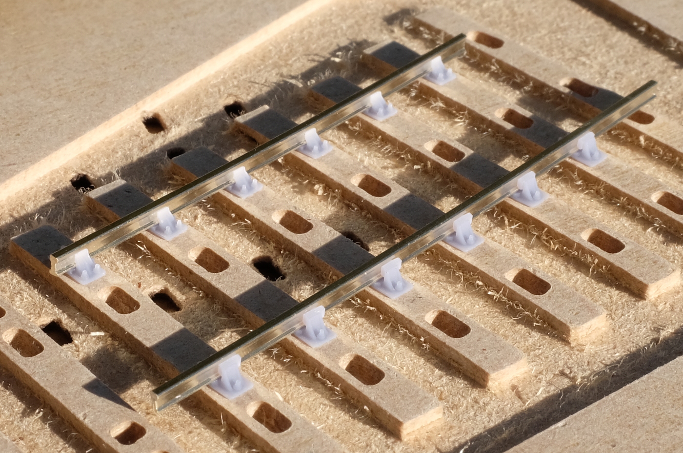
No flanges, no webs, no nibs, no snibs.
A desktop CNC engraver is about the same cost as an FDM printer, much less expensive than a laser cutter and no smoke or fire risks. The dust can be dealt with by rigging up a domestic vacuum cleaner attachment.
The only downside is that it is very noisy. It needs high spindle speeds for the small cutters, and the desktop machines are not especially robust. It would need to be in cast iron to run quietly at high speed.
cheers,
Martin.
Hi James,
Prompted by a post on RMweb, I'm wondering now if I should have included a sample of a CNC-milled base in the goody box for Scaleforum? This is EM gauge in MDF:
No flanges, no webs, no nibs, no snibs.
A desktop CNC engraver is about the same cost as an FDM printer, much less expensive than a laser cutter and no smoke or fire risks. The dust can be dealt with by rigging up a domestic vacuum cleaner attachment.
The only downside is that it is very noisy. It needs high spindle speeds for the small cutters, and the desktop machines are not especially robust. It would need to be in cast iron to run quietly at high speed.
cheers,
Martin.
message ref: 7992
Phil G
Member
- Location
- New Zealand
Hi Martin,
would I be right in assuming for the example you show in the photo, Plug track has exported a DXF File and then some CAM software is required to actually create the G code?
Also worth noting the dust created is more or less on a par with the smoke from a laser. Fully acknowledging a Laser does have a added fire risk as well.
Maybe the answer is a CNC router, instead if a desk top CNC engraver?
The Masuter pro
https://www.foxalien.com/en-nz/collections/masuter-series/products/cnc-router-masuter-pro
or the Genmitsu ProverXL
https://www.sainsmart.com/products/genmitsu-proverxl-4030-cnc-router-with-carveco-maker-subscription
as two examples.
Both are nominal 450 x 450 mm X and Y size. There also both expandable in table size, you can get close on a meter cutting length in the X axis. In addition both can also have Laser fitted if required.
cheers
Phil,
message ref: 7993
Steve_Cornford
Member
- Location
- Brighton, East Sussex
Hi Martin,
I hope this is a helpful suggestion:-

Any chance of moving "3-D support raft label text height" from this screen on the Timbers tab to the "support rafts" screen on the supports tab?
ie this screen:-

Regards Steve
I hope this is a helpful suggestion:-
Any chance of moving "3-D support raft label text height" from this screen on the Timbers tab to the "support rafts" screen on the supports tab?
ie this screen:-
Regards Steve
message ref: 7994
- Location
- West of the Severn UK
- Info
- .
Enjoy using Templot?
Thanks.
Please do not send requests for help direct to me via email.
Post your questions on the forum where everyone can see them and add
helpful replies.
@Phil GHi Martin,
would I be right in assuming for the example you show in the photo, Plug track has exported a DXF File and then some CAM software is required to actually create the G code?
Also worth noting the dust created is more or less on a par with the smoke from a laser. Fully acknowledging a Laser does have a added fire risk as well.
Maybe the answer is a CNC router, instead if a desk top CNC engraver?
The Masuter pro
https://www.foxalien.com/en-nz/collections/masuter-series/products/cnc-router-masuter-pro
or the Genmitsu ProverXL
https://www.sainsmart.com/products/genmitsu-proverxl-4030-cnc-router-with-carveco-maker-subscription
as two examples.
Both are nominal 450 x 450 mm X and Y size. There also both expandable in table size, you can get close on a meter cutting length in the X axis. In addition both can also have Laser fitted if required.
cheers
Phil,
Hi Phil,
I don't understand about the smoke and dust? You can't capture smoke in a domestic vacuum cleaner, it needs an external extractor fan/duct.
For sufficiently accurate miling I think it needs a screw-driven miller rather than a belt-driven engraver. I think I posted this a few days ago as a possible:
Carbide Create (free) is the only CAM program I have found which will import DXF files (2-D) from Templot and create gcode for the CNC cutter paths:
https://carbide3d.com/carbidecreate/
This is the equivalent of the slicer software for 3D printing.
cheers,
Martin.
message ref: 7995
Hi Martin,
would I be right in assuming for the example you show in the photo, Plug track has exported a DXF File and then some CAM software is required to actually create the G code?
Also worth noting the dust created is more or less on a par with the smoke from a laser. Fully acknowledging a Laser does have a added fire risk as well.
Maybe the answer is a CNC router, instead if a desk top CNC engraver?
The Masuter pro
https://www.foxalien.com/en-nz/collections/masuter-series/products/cnc-router-masuter-pro
or the Genmitsu ProverXL
https://www.sainsmart.com/products/genmitsu-proverxl-4030-cnc-router-with-carveco-maker-subscription
as two examples.
Both are nominal 450 x 450 mm X and Y size. There also both expandable in table size, you can get close on a meter cutting length in the X axis. In addition both can also have Laser fitted if required.
cheers
Phil,
Yes, as shown in the export dialog below. All of the exports are models that rely on external CAM software i.e an FDM slicer such as Cura for FDM printers, or a Resin slicer such as Chitubox for resin printers. Fusion 360 is more than capable of importing DXF files and creating gcode, but there are other CAM options too.
When using a CNC router to cut timber bases, you typically only need to define a couple of Z cutting depths, and this is something easy to do manually in CAM from a 2D file. You could also import a 3D model in Fusion 360 and use that to generate gcode, but it's not really saving you much - you still have to define tools and generate toolpaths.
FDM and Resin slicers take 3D models directly because the many (potentially thousands of) layers in a large 3D print make it utterly impractical to do any other way.
message ref: 7996
Phil G
Member
- Location
- New Zealand
I don't understand about the smoke and dust? You can't capture smoke in a domestic vacuum cleaner, it needs an external extractor fan/duct.
Hi Martin,
The MDF Smoke/ dust comment was only that both do roughly equally damage to the lungs.
re vacuum comment, I am doing some experiments with an old shop wet and dry vacuum, basically adding some BBQ charcoal (carbon) inside the filter basket. Seems to be working great at absorbing smoke fumes, all be right now all I am laser cutting is % vs Speed test cuts.
Thanks for the tip on carbide create,
RE the leadscrew vs belt, I would agree if we were cutting metal, or even heavy cuts in MDF but
with a 1/8" cutter, it does not seem an issue at all.
What I like is the much bigger cutting area, it allows for a full turnout to be made in one go for example.
cheers
Phil
message ref: 7997
Phil G
Member
- Location
- New Zealand
You could also import a 3D model in Fusion 360
Hi Ian,
unless you know something I don't Fusion 360 is not free software,( unless you can prove your a student) I am aware you can get some limited access to Fusion 360 for free, but it only gives a max of 10 projects. I only have 1 left
cheers
Phil,
message ref: 7999
- Location
- West of the Severn UK
- Info
- .
Enjoy using Templot?
Thanks.
Please do not send requests for help direct to me via email.
Post your questions on the forum where everyone can see them and add
helpful replies.
@Phil GFusion 360 is more than capable of importing DXF files and creating gcode, but there are other CAM options too.
Hi Phil,
There may be, but I tried many of them and the ONLY one which would accept DXF files from Templot for 2.5-D CAM operations (at least in the free versions) was Carbide Create. It's free because it is essentially a marketing tool for that company's milling cutters.
I'm not sure where you are going with that post? It's all been covered before in the CNC topic:
https://85a.uk/templot/club/index.php?threads/cnc-milled-timbers-instead-of-laser-cut.276/
cheers,
Martin.
message ref: 8000
- Location
- West of the Severn UK
- Info
- .
Enjoy using Templot?
Thanks.
Please do not send requests for help direct to me via email.
Post your questions on the forum where everyone can see them and add
helpful replies.
@Phil GRE the leadscrew vs belt, I would agree if we were cutting metal, or even heavy cuts in MDF but
with a 1/8" cutter, it does not seem an issue at all.
Hi Phil,
I'm not questioning the ability to make a cut, but we need accurate finished dimensions too. Belt drives work for FDM printing (and laser cutting) because there is no external load on the head for the X-Y axis and only minimal load on Z. For cutting it needs a screw, and preferably a recirculating ballscrew, for accurate results.
cheers,
Martin.
message ref: 8001
Phil G
Member
- Location
- New Zealand
Hi Martin,
Carbide create no longer seems to have a free option.
However I do agree It should be discussed in the CNC topic.
On a totally different subject which is Plug track related I seem to have had a brain explosion, I am sure you covered tis in a Zoom topic but I can't find it.
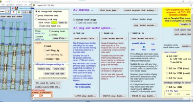
In the attached Screenshot I need to remove The 4 S1 Chairs that are more or less over the vee crossing chairs of the next turnout. How do you remove individual chairs.

Sorry for such a dumb question.
Cheers
Phil
Carbide create no longer seems to have a free option.
However I do agree It should be discussed in the CNC topic.
On a totally different subject which is Plug track related I seem to have had a brain explosion, I am sure you covered tis in a Zoom topic but I can't find it.
In the attached Screenshot I need to remove The 4 S1 Chairs that are more or less over the vee crossing chairs of the next turnout. How do you remove individual chairs.
Sorry for such a dumb question.
Cheers
Phil
message ref: 8002
- Location
- West of the Severn UK
- Info
- .
Enjoy using Templot?
Thanks.
Please do not send requests for help direct to me via email.
Post your questions on the forum where everyone can see them and add
helpful replies.
@Phil GCarbide create no longer seems to have a free option.
Hi Phil,
As so often, I feel that I'm on a different planet from everyone else.
I just downloaded and installed Carbide Create, without so much as entering an email address, let alone paying, and the result is:
cheers,
Martin.
message ref: 8003
Charles Orr
Member
- Location
- Leicester UK
Hi Phil,Hi Ian,
unless you know something I don't Fusion 360 is not free software,( unless you can prove your a student) I am aware you can get some limited access to Fusion 360 for free, but it only gives a max of 10 projects. I only have 1 left
cheers
Phil,
I have a Fusion360 (not for commercial use) account.
You are only allowed 10 editable projects to be open at any one time. Once you get to this limit you must make the others Read-Only.
Then you can start a new project.
Best regards
Charles
message ref: 8004
James Walters
Member
- Location
- Bexhill West
Hi Martin, I have a Roland CNC engraver at work and can produce a sample to add to the display.@James Walters
Hi James,
Prompted by a post on RMweb, I'm wondering now if I should have included a sample of a CNC-milled base in the goody box for Scaleforum? This is EM gauge in MDF:
No flanges, no webs, no nibs, no snibs.
A desktop CNC engraver is about the same cost as an FDM printer, much less expensive than a laser cutter and no smoke or fire risks. The dust can be dealt with by rigging up a domestic vacuum cleaner attachment.
The only downside is that it is very noisy. It needs high spindle speeds for the small cutters, and the desktop machines are not especially robust. It would need to be in cast iron to run quietly at high speed.
cheers,
Martin.
I use a Roland MDX-40A, and even though it is quite robust and has a proper high-speed spindle the racket it makes is very irritating.
I've found that MDF does knock the edge off of cutters relatively quickly which can be a pain as they are impossible to grind accurately by hand.
It'll be an interesting experiment to try though, and an option I'd not really considered before.
I'll keep you posted.
message ref: 8005
- Location
- West of the Severn UK
- Info
- .
Enjoy using Templot?
Thanks.
Please do not send requests for help direct to me via email.
Post your questions on the forum where everyone can see them and add
helpful replies.
@Phil GOn a totally different subject which is Plug track related I seem to have had a brain explosion, I am sure you covered tis in a Zoom topic but I can't find it.
In the attached Screenshot I need to remove The 4 S1 Chairs that are more or less over the vee crossing chairs of the next turnout. How do you remove individual chairs.
View attachment 6961
Sorry for such a dumb question.
Cheers
Phil
Hi Phil,
It's not a dumb question.
Select the timber. Untick the unwanted chair(s). Chairs count 1..4 across from the MS end to the TS end.
N.B. this is 100% temporary kludge until the full chair heaving function is done. It's NOT the final design.
cheers,
Martin.
message ref: 8006
Steve_Cornford
Member
- Location
- Brighton, East Sussex
Hi Phil,
To remove chairs , Real > Sove timbers... gives you:-

Select the timber containing the chairs you want to remove, then on the right hand side of the "shove timbers" window there is a panel headed "chairs" with a column of 4 chairs numbered 1-4 , untick the one you want to remove.
STeve
Edit Martin beat me to it...
To remove chairs , Real > Sove timbers... gives you:-
Select the timber containing the chairs you want to remove, then on the right hand side of the "shove timbers" window there is a panel headed "chairs" with a column of 4 chairs numbered 1-4 , untick the one you want to remove.
STeve
Edit Martin beat me to it...
message ref: 8007
Phil G
Member
- Location
- New Zealand
Hi Martin,
yes I did that,
and yes you can download a Templot file, however the export out options are limited to these machines only.
this web site explains it quite well.
https://carbide3d.com/learn/free-cnc-software/#:~:text=Carbide Create runs on Windows,Shapeoko CNC Router and Nomad.

Cheers
Phil
yes I did that,
and yes you can download a Templot file, however the export out options are limited to these machines only.
this web site explains it quite well.
https://carbide3d.com/learn/free-cnc-software/#:~:text=Carbide Create runs on Windows,Shapeoko CNC Router and Nomad.
Cheers
Phil
message ref: 8008
Phil G
Member
- Location
- New Zealand
Hi Martin/Steve,
Thanks guys I feel like a total dummy. I have just wasted over an hour in the timber shove screen moving the timbers etc, and the one thing I did not try was the 4 chair tick box.
Maybe I am wasting too much time on replying to other posts
cheers
Phil,
Thanks guys I feel like a total dummy. I have just wasted over an hour in the timber shove screen moving the timbers etc, and the one thing I did not try was the 4 chair tick box.
Maybe I am wasting too much time on replying to other posts
cheers
Phil,
message ref: 8009
- Location
- West of the Severn UK
- Info
- .
Enjoy using Templot?
Thanks.
Please do not send requests for help direct to me via email.
Post your questions on the forum where everyone can see them and add
helpful replies.
@Phil GHi Martin,
yes I did that,
and yes you can download a Templot file, however the export out options are limited to these machines only.
this web site explains it quite well.
https://carbide3d.com/learn/free-cnc-software/#:~:text=Carbide Create runs on Windows,Shapeoko CNC Router and Nomad.
View attachment 6968
Cheers
Phil
Apologies Phil. That must be a change since the previous version. I still have the previous version on my Windows10 system and I will copy it across. That doesn't help anyone else of course.
cheers,
Martin.
message ref: 8010
Phil G
Member
- Location
- New Zealand
Hi Steve,
on your screenshot you don't seem to have the FDM timber webs showing. Is that a setting you can use to switch FDM web outline off? Here is my export page as a screenshot, what I am I missing this time?
cheers
Phil,
on your screenshot you don't seem to have the FDM timber webs showing. Is that a setting you can use to switch FDM web outline off? Here is my export page as a screenshot, what I am I missing this time?
cheers
Phil,
Attachments
message ref: 8011
- Location
- West of the Severn UK
- Info
- .
Enjoy using Templot?
Thanks.
Please do not send requests for help direct to me via email.
Post your questions on the forum where everyone can see them and add
helpful replies.
@Phil GHi Steve,
on your screenshot you don't seem to have the FDM timber webs showing. Is that a setting you can use to switch FDM web outline off? Here is my export page as a screenshot, what I am I missing this time?
cheers
Phil,
Hi Phil,
To remove any element from the export, set its combo to blank (right-click on it):
As before, this is all still unfinished stuff.
However, I have made the decision today NOT to proceed with a re-write and a proper new user interface for these 3D exports. It is all getting too much. It will have to remain as it is for the foreseeable future.
cheers,
Martin.
message ref: 8012
Phil G
Member
- Location
- New Zealand
Hi Martin,
Out of interest, do the export Layers also affect what you see on the trackpad screen? and are they template specific? I mean before exporting.
Only asking as I also had a look at layers just before your post, and noticed one template has webs as an active export layer and the other did not, when back in the main trackpad it does seem to directly affect what your looking at. IE one has webs visible and the other one does not.
I am not even sure how I managed to create two templates from a crossover that are so different in appearance.
Cheers
Phil
message ref: 8013
- Location
- West of the Severn UK
- Info
- .
Enjoy using Templot?
Thanks.
Please do not send requests for help direct to me via email.
Post your questions on the forum where everyone can see them and add
helpful replies.
@Phil GHi Martin,
Out of interest, do the export Layers also affect what you see on the trackpad screen? and are they template specific? I mean before exporting.
Only asking as I also had a look at layers just before your post, and noticed one template has webs as an active export layer and the other did not, when back in the main trackpad it does seem to directly affect what your looking at. IE one has webs visible and the other one does not.
I am not even sure how I managed to create two templates from a crossover that are so different in appearance.
Cheers
Phil
Hi Phil,
Sorry, I can't answer this in a single reply. It needs a couple of hours preparing a proper web page in the plug track docs.
Use the preview button on the export dialog to see what you are actually going to get.
cheers,
Martin.
message ref: 8014
James Walters
Member
- Location
- Bexhill West
Hi Phil,
I hope I'm understanding your situation correctly.
And I think I'm correct in saying yes, the export layers do affect what you see on the trackpad screen when you are trying to export the control template.
A good way to check and to build understanding of what is going on is to click the OMIT ALL button on the layer tab of the export dxf output dialogue. If you then click REBUILD NOW, you should be able to see the layers 'switch off'. Clicking ALL BLACK, and then REBUILD NOW will bring them all to life again. DEFAULTS will get you back to where you were.
If you experiment with these controls on the templates which are displaying differently you should be able to identify which layers are turned on or off for each template.
Having played with those controls, you'll be able to click DEFAULTS for each template to make them both display the same.
Or, just check the webs layer on the template which is missing them.
I'm bound to have got some of that wrong, but if I have it'll do no harm to play with those controls and see what happens.
That's what I did when I had a similar situation, and the result of the experiment is that I learnt quite a lot.
I hope that is of help.
message ref: 8015
Steve_Cornford
Member
- Location
- Brighton, East Sussex
Hi Phil,
I had not touched the "layers" dialogue tab on the export screen.
At that moment in time I had not "stored" the templates to background as "timbering bricks"

In the bottom left hand is the pop-up "experimental 3D" window, and on this screen capture all the boxes are unticked, as they were when I stored the templates in the previous screen print, so they are not "bricklaying" templates and thus have no "timbering" brick webs.
Well at least I think that is the explanation!
In the end I did repeat the store to background as I wanted to add some text to the chair raft I was trying to generate.

4mm S1 slotted chairs & lose jaws
Steve
I had not touched the "layers" dialogue tab on the export screen.
At that moment in time I had not "stored" the templates to background as "timbering bricks"
In the bottom left hand is the pop-up "experimental 3D" window, and on this screen capture all the boxes are unticked, as they were when I stored the templates in the previous screen print, so they are not "bricklaying" templates and thus have no "timbering" brick webs.
Well at least I think that is the explanation!
In the end I did repeat the store to background as I wanted to add some text to the chair raft I was trying to generate.
4mm S1 slotted chairs & lose jaws
Steve
message ref: 8016
- Location
- West of the Severn UK
- Info
- .
Enjoy using Templot?
Thanks.
Please do not send requests for help direct to me via email.
Post your questions on the forum where everyone can see them and add
helpful replies.
@Phil G @James Walters @Steve_Cornford
Don't forget that you also have these options.
This controls what you actually see on the trackpad for background templates, not what actually gets exported. This is to keep the screen less cluttered.

cheers,
Martin.
Don't forget that you also have these options.
This controls what you actually see on the trackpad for background templates, not what actually gets exported. This is to keep the screen less cluttered.
cheers,
Martin.
message ref: 8017
Steve_Cornford
Member
- Location
- Brighton, East Sussex
In fact I am wrong, James is right.
It was because I had clicked the "chairs only" radio button on the DXF dialogue & then pressed the review function, then having produced the review and closed the DXF dialogue the webs had disappeared from the trackpad display.
Steve
It was because I had clicked the "chairs only" radio button on the DXF dialogue & then pressed the review function, then having produced the review and closed the DXF dialogue the webs had disappeared from the trackpad display.
Steve
message ref: 8018
Even without the read-only workaround to the project limit, 10 may be enough for Templot users.Hi Ian,
unless you know something I don't Fusion 360 is not free software,( unless you can prove your a student) I am aware you can get some limited access to Fusion 360 for free, but it only gives a max of 10 projects. I only have 1 left
cheers
Phil,
message ref: 8019
James Walters
Member
- Location
- Bexhill West
That's great, I'd never seen this before I'm rather embarrassed to admit.@Phil G @James Walters @Steve_Cornford
Don't forget that you also have these options.
This controls what you actually see on the trackpad for background templates, not what actually gets exported. This is to keep the screen less cluttered.
View attachment 6980
cheers,
Martin.
This is the joy of Templot for me, the more one learns, the more one realises there is to learn. It's like learning to play a musical instrument. I'm now one small step closer to becoming a
.message ref: 8020
Phil G
Member
- Location
- New Zealand
Hi Steve and James,In fact I am wrong, James is right.
It was because I had clicked the "chairs only" radio button on the DXF dialogue & then pressed the review function, then having produced the review and closed the DXF dialogue the webs had disappeared from the trackpad display.
Steve
Thanks I half got there myself and then had to take my daughter to work.
I have also figured out how I got to where I got to. I am not sure its wrong it just had some unexpected consequences,
I am working on a crossover and keep swapping back and forth between the two templates. in oder to do this I am using delete to control as and when I need to work on each half once updated I save to box file. what this does however is also update any other changes I make. In there process of trying to understand why so many lines on one half I did play with layers switching thing off and the rebuilding hence why I ended up with two very different looking templates.
Martin in your post you show a dialog box and the correct answer, however how do I access that dialog box? aslo is it global or template specific?
cheers
Phil
message ref: 8023
Phil G
Member
- Location
- New Zealand
If your one step closer to being a Ninja. I am about a 1/4 step being closer to being Japanese, so I have a hell of a way to go yetThat's great, I'd never seen this before I'm rather embarrassed to admit.
This is the joy of Templot for me, the more one learns, the more one realises there is to learn. It's like learning to play a musical instrument. I'm now one small step closer to becoming a
cheers
Phil
message ref: 8024
James Walters
Member
- Location
- Bexhill West
It's here:

message ref: 8025
Related topics
- Replies
- 67
- Views
- 3K
- Replies
- 20
- Views
- 589
- Article
- Replies
- 20
- Views
- 475
- Replies
- 9
- Views
- 786