Wow. That stopped me in my tracks. I think I made a big mistake when starting on the 3D chairing experiments in assuming that everyone likely to be following them would be well-versed in Templot and track building. Putting that right all through Templot could be a lot of work.
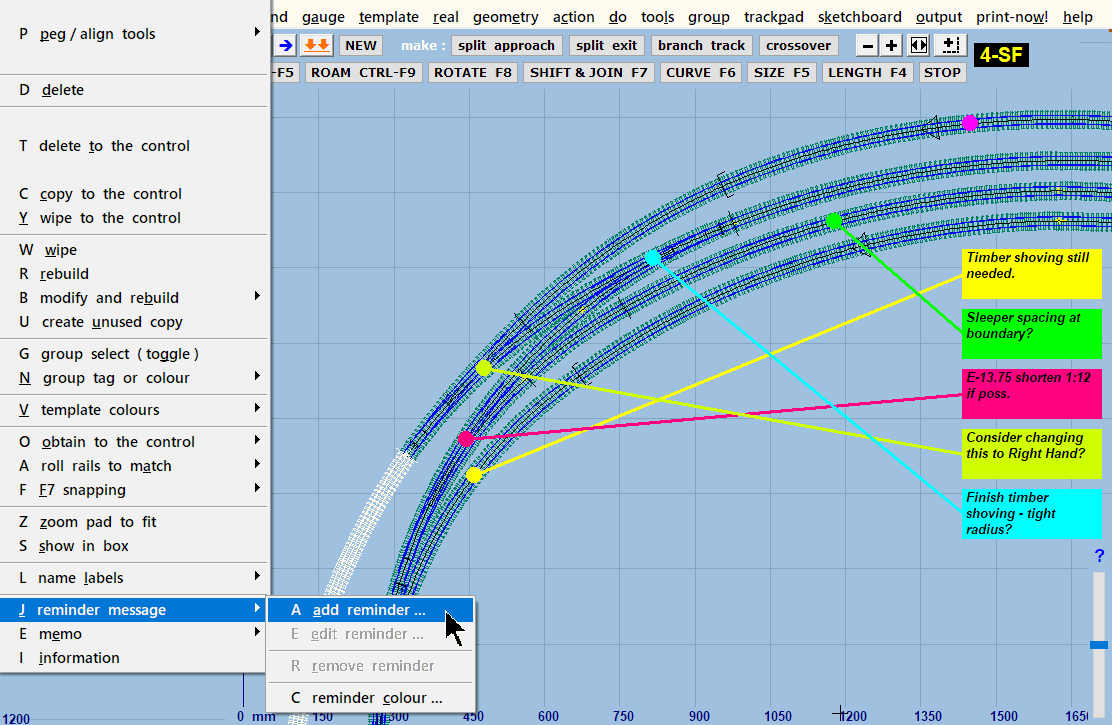
I'm making an emergency change to the wording, and will get the next update out as soon as possible:
View attachment 8506
This is a wording change only -- no change to the actual functions.
@Michael Woods
Hi Michael,
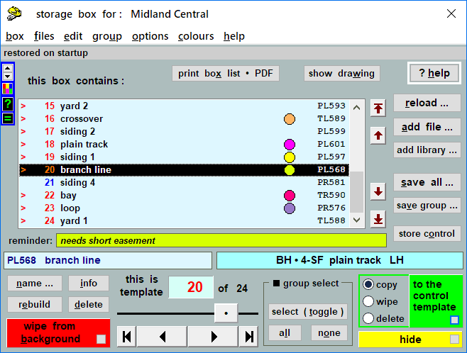
I'm sorry you have a problem. You will need to re-make these 3 chairs:
View attachment 8507
using the original 0.71mm flangeway setting for S scale.
The new chairs will be shorter, which means the existing sockets will be too long. However you may be able to use the existing base if you fix the chairs with a gap-filling adhesive such as epoxy, carefully ensuring the chairs are centralized in the socket.
Reducing the crossing-flangeway gap will also move the position of the knuckle bend, needing the wing rails to be re-made. This will also likely cause the right-most chair to change from XN to ZY type which is narrower, and will therefore need some filler in the sides of the socket too.
If instead you prefer to make a new timbering base and this V-crossing is a
regular type, making a new base from a new template with a reduced flangeway gap will cause it to be slightly longer than the previous one. To avoid disrupting your track plan, you could get it to match the length of the previous one by increasing the
crossing entry straight using the
SHIFT+F11 mouse action.
I hope this problem isn't too much of a setback for you.
Martin.
 Search

")