Templot Club forums powered for Martin Wynne by XenForo :

TEMPLOT 3D PLUG TRACK - To get up to speed with this experimental project click here.   To watch an introductory video click here.   See the User Guide at Bexhill West.

  • The Plug Track functions are experimental and still being developed. Some of the earlier pages of this topic are now out-of-date.

    For an updated overview of this project see this topic.   For some practical modelling aspects of using Plug Track see Building 3D Track.

    The assumption is that you have your own machines on which to experiment, or helpful friends with machines. Please do not send Templot files to commercial laser cutting or 3D printing firms while this project is still experimental, because the results are unpredictable and possibly wasteful.

    Some pages of this and other topics include contributions from members who are creating and posting their own CAD designs for 3D printing and laser-cutting. Do not confuse them with Templot's own exported CAD files. All files derived from Templot are © Martin Wynne.
  • The Plug Track functions are experimental and still being developed.

    For an updated overview of this project see this topic.   For some practical modelling aspects of using Plug Track see Building 3D Track.

    The assumption is that you have your own machines on which to experiment, or helpful friends with machines. Please do not send Templot files to commercial laser cutting or 3D printing firms while this project is still experimental, because the results are unpredictable and possibly wasteful.

    Some pages of this and other topics include contributions from members who are creating and posting their own CAD designs for 3D printing and laser-cutting. Do not confuse them with Templot's own exported CAD files. All files derived from Templot are © Martin Wynne.

Experimental 3D plug track - up to version 244c

Quick reply >
Hi Martin,

This will be a useful extra function. And the benefit of being able to store these settings in the .box file will be typical of one of those less-obvious but well thought-out Templot ideas. (y)

As I experiment more with NIBS & SNIBS, I'm tending to default to 0.6mm for the NIB width and length. Also, (and contrary to a previous post of mine) I'm tending to set the Snib space to 0mm, such that the waste drops out of the fret.
Therefore, I'm thinking that there is benefit to these being the default values.
These are the export values which I change with the greatest frequency, (every time).
What do others with laser experience think?

If folks think there is benefit to this suggestion, then could the default SNIB length be reduced slightly such that the snibs only just cross-over, with a standard* timber spacing? This would eliminate most of the SNIB adjustments in most cases, and massively save time. Time saved will offset and encourage (I think) the time taken to make the adjustments in Templot, rather that in laser software.

Where timbers have been shoved apart to the extreme the snibs would obviously not cross, which would leave a NIB (of sorts), which wouldn't be the end of the world. The effort to cut them out post-cutting would be be much less than making the adjustments in Templot.

This will be difficult to understand for anyone who hasn't yet made use of the Nibs & Snibs function, in which case don't worry about it. :)

Just thoughts,

James

*standard - I know there's no such thing, but hopefully you get my drift.
 
_______________
message ref: 9954
Further to the above, I think there is value in changing the SNIB nomenclature in the layers tab of the export setting to match that which you have incorporated into the shove timbers control. The NE,SE,SW,NW compass designations aren't so clear when working on a template displayed vertically on-screen.

Again, just an idea. :)
 
_______________
message ref: 9956
Further to the above, I think there is value in changing the SNIB nomenclature in the layers tab of the export setting to match that which you have incorporated into the shove timbers control. The NE,SE,SW,NW compass designations aren't so clear when working on a template displayed vertically on-screen.

Again, just an idea. :)
@James Walters

Hi James,

That has already been done. :) The compass idea was silly and doesn't work for RH templates where north and south were swapped over.

We now have T and M for Turnout and Main side of the template, and N and F for Near and Far side of the timber from the CTRL-0 datum end of the template.

The same applies to the designations for the timber flanges.

p.s. for plain track, the Main side is indicated by the flag on the end marker.

cheers,

Martin.
 
_______________
message ref: 9957
Hi Martin,

This will be a useful extra function. And the benefit of being able to store these settings in the .box file will be typical of one of those less-obvious but well thought-out Templot ideas. (y)

As I experiment more with NIBS & SNIBS, I'm tending to default to 0.6mm for the NIB width and length. Also, (and contrary to a previous post of mine) I'm tending to set the Snib space to 0mm, such that the waste drops out of the fret.
Therefore, I'm thinking that there is benefit to these being the default values.
These are the export values which I change with the greatest frequency, (every time).
What do others with laser experience think?

If folks think there is benefit to this suggestion, then could the default SNIB length be reduced slightly such that the snibs only just cross-over, with a standard* timber spacing? This would eliminate most of the SNIB adjustments in most cases, and massively save time. Time saved will offset and encourage (I think) the time taken to make the adjustments in Templot, rather that in laser software.

Where timbers have been shoved apart to the extreme the snibs would obviously not cross, which would leave a NIB (of sorts), which wouldn't be the end of the world. The effort to cut them out post-cutting would be be much less than making the adjustments in Templot.

This will be difficult to understand for anyone who hasn't yet made use of the Nibs & Snibs function, in which case don't worry about it. :)

Just thoughts,

James

*standard - I know there's no such thing, but hopefully you get my drift.
@James Walters

Hi James,

Many thanks for your thoughts.

This is complex. What is really needed is a means to adjust each snib individually, but that would be very tedious to do, and no easier than doing the same thing in CAD. I spent a long time originally trying different options to avoid the need for that.

I'm reluctant to set the default snib space to zero. It would mean a great many users would never discover the option to have a space, and may have pieces falling loose on a machine where it causes problems.

But to make it easier to omit the snib spaces, I'm adding yet another tick-box so that the spaces can be omitted with a single click to untick this:

snib_space_option.png


The first problem in finding a solution is that the nibs and space sizes are machine-specific and don't change with different model scales. Whereas the snib lengths do need to do that.

Reducing the snib lengths is tricky. As an experiment I'm reducing the 2nd snib angle from 1:1 (45degs) to 1:2. The critical condition is where square-on timbers increase in length by 6" from one timber to the next:


snib_intersects.png


That's with no snib spaces -- slightly more overlap if there is a space.

It has the 1st snib extent at 5.75" and the 2nd snib extent at 15" (full size) in 4mm/ft scale:

snib_settings.png


For plain track, and the Main side of the turnout timbers, the 2nd snib length is reduced to 10":

snib_intersects_plain_track.png


This ensures a solid rib between double track, which I assume is needed to create a viable timbering fret.

For equalized timbering, the 2nd snib can be 12" on both sides of a turnout template.

I'm still experimenting with all this, but there will be something along these lines in 244a to try out and no doubt need further tweaking. :)

cheers,

Martin.
 
_______________
message ref: 9962
Hi Guys,
Am I missing something here,
looking at Martins photo above, will that not result in all the sections between the sleepers falling out? Or is that what your trying to achieve. I understand that's the spacer gap between the snibs which will prevent this, and not the angle of the snib line which you are talking about.

Also back on the 27th of November I asked weather it was possible to have separate offsets for the socket kerf and the timber outline kerf.
The advantage of having separate kerf values is you can independently set the correct kerf for the socket (critical for correct gauging)
separate values would then allow more flexibility, if say the wall between the socket and the timber outline was too thin you could select a bigger kerf offset for the timber and adjust it that way. I understand that could end up with slightly over width and length timber but that may be the best compromise.
cheers
Phil,
 
_______________
message ref: 9967
Last edited:
Am I missing something here,
looking at Martins photo above, will that not result in all the sections between the sleepers not falling out? Or is that what your trying to achieve. I understand that's the spacer gap between the snibs which will prevent this, and not the angle of the snib line which you are talking about.
@Phil G

Hi Phil,

Yes, the intention is that if you set the snib spaces to zero, the waste between the timbers falls free. If you don't, it doesn't.

The intention in reducing the snib angle and shortening the snib lengths is to reduce the number of conflicts which need editing in the laser CAD. Combined with the option to omit individual snibs, hopefully none.

I'm not convinced that having different kerf values is a good idea. It is intended to be a single machine setting, i.e. from the laser-cutter, not part of the track design. There are already several other settings to adjust the size of the sockets and the timber width. There is no need to compromise on the timber length, and only plain track sleepers may need the width tweaking, and not turnout timbers:


timbering_data1.png


I'm doing my best to accommodate the needs of laser cutting, but I don't want it to take over the project because my own interest is primarily in FDM-printed timbering. I can't see laser-cutting becoming a mainstream home-hobby process, only a minority of Templot users are likely to have a laser-cutter. Whereas FDM and resin printing are rapidly gaining in popularity.

cheers,

Martin.
 
_______________
message ref: 9968
Hi Martin,
I understand what your saying here, but to be honest everything i have tried is telling me whilst the theory of a single kerf is correct, the actual measurements don't follow that. I am wondering if the close proximity of the 4 cuts that make up the socket slot are the reason. IE the wood is somehow being impacted by previous cuts already. If I don't cad correct. I can get the slots right but the timbers wrong on a single kerf setting. That's where the idea of separate kerf has come from.

I understand if its not on your list of things to do, don't worry I can still carry on manually correcting.in my cad system.
I would also be keen to understand if other laser users are having the same issue though? As I know I have a bit of an accuracy issue on my Y axis currently.
Cheers
Phil,

PS with the likes of the Creality 2 hitting the market, I am not at all sure Laser cutting will remain a backwater option, as you are suggesting for much longer.
I know there is the fire issue to contain with, and the fumes, but just looking on you tube there are now far more videos of lasers than bed slinger FDM printers for example.
 
_______________
message ref: 9969
I understand if its not on your list of things to do, don't worry I can still carry on manually correcting.in my cad system.
@Phil G

Hi Phil,

No need to use CAD, just change the sleeper width for the control template, then modify group to match:


sleeper_width.png


That dialog normally asks for full size inches. But if you prefix the figure with a letter s you can enter your scale size in mm instead (make sure you have set your model scale first).

So instead of the default 10" wide sleepers (3.33mm in EM), you could enter say s3.45 to increase the the sleeper kerf lines by 0.12mm on the sleeper width, i.e. 0.06mm per side. Nothing else would be affected. It all gets saved in in the BOX file.

For more about other input conversion prefix letters, click the ? help button.

Martin.
 
_______________
message ref: 9970
Sorry if I appear a bit of a Luddite but at leaset initially it would be useful to be able to alter the plug to a different shape, i.e. round. That way the chairs could be used on say plywood or abs timbers with the use of a pre-drilled hole. That way you could rely on existing gauges to set the track, the holes having been drilled slightly oversize to allow a bit of adjustment. I am not over keen on the idea of using an FDM printer for the timbers as has been said, nothing looks better than wood as timbering. A laser would be nice but a bit OTT at the moment.

I am currently using a couple of new superglues, which work well, one of which especially when used with abs chairs and plywood timbers, "Woldoclean Professional superglue Plastic", the other is Welding High Strength oily glue, which seems to work with just about anything. So construction should be quite quick.

Both available from Amazon by the way.

Otherwise I can see me printing the chairs with a peg
 
_______________
message ref: 9973
Sorry if I appear a bit of a Luddite but at least initially it would be useful to be able to alter the plug to a different shape, i.e. round.
@Stephen Freeman

Hi Stephen,

There is no way I'm going there with plug track. 4 reasons:

1. the rectangular plugs set the chair at the correct angle on the timber. This allows the chairs to be assembled into the base without the rail in place.

2. the rectangular plugs allow space for the loose jaw slots.

3. the rectangular plugs support the delicate corners of the chair base in resin-printing.

4. the whole reason I developed plug track is to allow dry assembly without glue -- I can't stand the pong of butanone, and most of the other solvents aren't much better. And also without needing gauge tools.

Of course it's your railway. You can easily export Templot chairs without plugs, and add whatever you want in CAD:


no_plug.png


no_pyramid.png


no_plug_chairs.png


cheers,

Martin.
 
_______________
message ref: 9975
Hi Martin - if I adjust the radius of a turnout will the check rail chairs change (assume same flangeway)...in other words can i just interchange or will i need to recreate the STL. I think the answer is that they will stay the same.....but want to check with you.
 
_______________
message ref: 9976
Hi Michael,

Hopefully the check gauge will remain the same, but if the turnout radius requires gauge widening then the gap between the check rail and the stock rail will increase.

The real railway had check chairs that increased in 1/4 inch increments upto 3/4 inch.
 
_______________
message ref: 9977
Hi Martin - if I adjust the radius of a turnout will the check rail chairs change (assume same flangeway)...in other words can i just interchange or will i need to recreate the STL. I think the answer is that they will stay the same.....but want to check with you.
@Michael Woods

Hi Michael,

The CC chairs are interchangeable on any template, regardless of size or curving, provided you haven't set any gauge-widening.

The CCL and CCR chairs are similarly interchangeable, provided you have the fixed option set. It's the default in the current program update (243a).

Here is a scruff video clip (silent) showing how to create CC chairs in bulk (and some S1J chairs):

https://flashbackconnect.com/Default.aspx?id=vChPfi0obFDKpkop-D1jww2

The video is for 4mm/ft scale. For S you will need to change the settings... to fit your printer:


multi_settings1.png


cheers,

Martin.
 
_______________
message ref: 9978
@Michael Woods

Hi Michael,

The CC chairs are interchangeable on any template, regardless of size or curving, provided you haven't set any gauge-widening.

The CCL and CCR chairs are similarly interchangeable, provided you have the fixed option set. It's the default in the current program update (243a).

Here is a scruff video clip (silent) showing how to create CC chairs in bulk (and some S1J chairs):

https://flashbackconnect.com/Default.aspx?id=vChPfi0obFDKpkop-D1jww2

The video is for 4mm/ft scale. For S you will need to change the settings... to fit your printer:


View attachment 8379

cheers,

Martin.
This is great - thank you. The gauge and flangeway widening are the same.....thanks to Phil too.
 
_______________
message ref: 9979
@Michael Woods

For a similar video clip explaining the fixed CCL and CCR chairs and showing how to create them in bulk I have extracted a clip from a recent ZOOM meeting:

https://flashbackconnect.com/Default.aspx?id=pVVvsihSq_inlNZ_SrOgkw2

To create the loose jaws for them the sequence is the same as for the CC chairs in the previous clip. Note that the loose jaws on the check rail side are not interchangeable with any other chairs, they are for fixed CCL and CCR chairs only.

Martin.
 
_______________
message ref: 9981
@James Walters

Hi James,

Many thanks for your thoughts.

This is complex. What is really needed is a means to adjust each snib individually, but that would be very tedious to do, and no easier than doing the same thing in CAD. I spent a long time originally trying different options to avoid the need for that.

I'm reluctant to set the default snib space to zero. It would mean a great many users would never discover the option to have a space, and may have pieces falling loose on a machine where it causes problems.

But to make it easier to omit the snib spaces, I'm adding yet another tick-box so that the spaces can be omitted with a single click to untick this:

View attachment 8360


The first problem in finding a solution is that the nibs and space sizes are machine-specific and don't change with different model scales. Whereas the snib lengths do need to do that.

Reducing the snib lengths is tricky. As an experiment I'm reducing the 2nd snib angle from 1:1 (45degs) to 1:2. The critical condition is where square-on timbers increase in length by 6" from one timber to the next:


View attachment 8358

That's with no snib spaces -- slightly more overlap if there is a space.

It has the 1st snib extent at 5.75" and the 2nd snib extent at 15" (full size) in 4mm/ft scale:

View attachment 8359


For plain track, and the Main side of the turnout timbers, the 2nd snib length is reduced to 10":

View attachment 8357


This ensures a solid rib between double track, which I assume is needed to create a viable timbering fret.

For equalized timbering, the 2nd snib can be 12" on both sides of a turnout template.

I'm still experimenting with all this, but there will be something along these lines in 244a to try out and no doubt need further tweaking. :)

cheers,

Martin.
I appreciate this is a tricky concept, my suggestions were really just thoughts based on quite a bit of experimentation. I certainly wasn't intending to create extra work for you. That said, it looks like you've got great ideas, and your concept of changing the snib angles such that they form a closed loop is genius. :)
 
_______________
message ref: 9982
@Michael Woods

For a similar video clip explaining the fixed CCL and CCR chairs and showing how to create them in bulk I have extracted a clip from a recent ZOOM meeting:

https://flashbackconnect.com/Default.aspx?id=pVVvsihSq_inlNZ_SrOgkw2

To create the loose jaws for them the sequence is the same as for the CC chairs in the previous clip. Note that the loose jaws are not interchangeable with any other chairs, they are for fixed CCL and CCR chairs only.

Martin.
Would you mind if I 'borrow' these clips Martin?, as per our Flashback discussions.

Best,

James
 
_______________
message ref: 9983
Would you mind if I 'borrow' these clips Martin?, as per our Flashback discussions.

Best,

James
@James Walters

Hi James,

Sure -- but I think I have already sent you the first one?

Both can be downloaded as FBR files instead of MP4 from the Flashback site. This will preserve better image quality if you re-record them and allow you to edit or add to the call-outs.

cheers,

Martin.
 
_______________
message ref: 9984
Hi Martin - making solid progress. One request that maybe you can consider. With the push fit chairs could you adjust the sensitivity of the slider so that the plug can (if required) be made a little loser? On the turnouts some of the larger chairs are coming up a bit tight and the ability to shrink the plug a bit more will help. I like the push fits working well for me but this would help. At the moment I am right up at the left hand slide so I cant get any more without a change to the slider sensitivity.

Many thanks

Michael
 
_______________
message ref: 10012
Hi Martin - making solid progress. One request that maybe you can consider. With the push fit chairs could you adjust the sensitivity of the slider so that the plug can (if required) be made a little loser? On the turnouts some of the larger chairs are coming up a bit tight and the ability to shrink the plug a bit more will help. I like the push fits working well for me but this would help. At the moment I am right up at the left hand slide so I cant get any more without a change to the slider sensitivity.

Many thanks

Michael
@Michael Woods

Hi Michael,

You can change the fit now. :)

Click this button:

press_fit_sizes.png


press_fit_sizes1.png


The slider is simply a means of tweaking the above 4 settings in one go without needing to enter dimensions. But you can make the plug-fit as loose or as tight as you wish by changing the above settings. Click the ?info button on each line for more details.

Note that these settings (and the slider) control the size of the socket, not the plug. Which means you would need to print a new timbering base to get the desired results. Moving the slider does not change the size of the plugs.

If the plugs are coming out generally oversize, the best solution is to reduce the shrinkage allowance on the chairs:

resin_shrinkage2.png


The design length of the plugs for the S1 and S1J chairs is 12.5" scale:

s1_plug_size.png


In S scale that equates to 4.96mm. If you have a suitable caliper you may be able to measure this and adjust the shrinkage accordingly. It can be fiddly to measure -- check that you have the chair base flush against the jaws of the caliper and square between them.

cheers,

Martin.
 
_______________
message ref: 10013
Hi Martin,
This maybe a silly question but what is 12.5 inch scale? As I have never heard of that before.

Or are you saying the design measurement of your plugs is to 12.5 inches, full size? then the chosen scale is just a divider number.
the more I think about it the more sense that makes.
cheers
Phil
 
_______________
message ref: 10023
Hi Martin,
This maybe a silly question but what is 12.5 inch scale? As I have never heard of that before.

Or are you saying the design measurement of your plugs is to 12.5 inches, full size? then the chosen scale is just a divider number.
the more I think about it the more sense that makes.
cheers
Phil
@Phil G

Hi Phil,

Yes. All the dimensions in plug track, and most other stuff in Templot, is stored internally at the full prototype size in inches. It is converted to the model equivalent at the current scale when shown in some of the dialogs. Or often left as the full-size inches where that makes more sense, such as the width of the timbers.

Except for dimensions where a prototype dimension doesn't make sense, such as the track gauge for say EM, etc.

The general rule in Templot is that if a dimension is quoted in inches, it refers to the full prototype size. If a dimension is quoted in mm, it refers to the model size at the current model scale. The only real exception to that is where you want the grid squares in inches on the trackpad.

This is why it is so important to set your model scale first at the start of a new Templot session before you do anything else.

If you set your model scale to 1:1 you can happily design full-size railway track. It uses a lot of filament. :)

cheers,

Martin.
 
_______________
message ref: 10024
If you set your model scale to 1:1 you can happily design full-size railway track. It uses a lot of filament. :)
I bet it would be more reliable though:)

re your post, good information, especially on the inches and mm bit. I was aware Templot projects most things at full size and uses the set gauge to scale accordingly.

what fooled me was the 12.5 inch scale comment. and the simple fact there is no such thing as a Templot chair plug at the 1:1 scale on the real railway network.
all make more sense with your explanation.
cheers
Phil.
 
_______________
message ref: 10025
@Michael Woods

Hi Michael,

You can change the fit now. :)

Click this button:

View attachment 8402

View attachment 8403

The slider is simply a means of tweaking the above 4 settings in one go without needing to enter dimensions. But you can make the plug-fit as loose or as tight as you wish by changing the above settings. Click the ?info button on each line for more details.

Note that these settings (and the slider) control the size of the socket, not the plug. Which means you would need to print a new timbering base to get the desired results. Moving the slider does not change the size of the plugs.

If the plugs are coming out generally oversize, the best solution is to reduce the shrinkage allowance on the chairs:

View attachment 8406


The design length of the plugs for the S1 and S1J chairs is 12.5" scale:

View attachment 8407

In S scale that equates to 4.96mm. If you have a suitable caliper you may be able to measure this and adjust the shrinkage accordingly. It can be fiddly to measure -- check that you have the chair base flush against the jaws of the caliper and square between them.

cheers,

Martin.
Thank you Martin - much appreciated. QQ(s) re the slider. I am probably misunderstanding something. When I move the slider to the left I get this set of adjustments...


1705833527627.png


But when I go to the right I get the same.

1705833589047.png


My chairs are perfect (for me) now so I dont want to change anything that will impact the chair / rail fit but if I want to make the timber socket bigger do I make the adjustment more possitive or negative. For example if I was to change the -0.03 on socket end clerance to 0 will the ease of fit become more or less?

Many thanks - Michael.
 
_______________
message ref: 10035
_______________
message ref: 10036
Thank you Martin - much appreciated. QQ(s) re the slider. I am probably misunderstanding something. When I move the slider to the left I get this set of adjustments...


View attachment 8429

But when I go to the right I get the same.

View attachment 8430

My chairs are perfect (for me) now so I dont want to change anything that will impact the chair / rail fit but if I want to make the timber socket bigger do I make the adjustment more possitive or negative. For example if I was to change the -0.03 on socket end clerance to 0 will the ease of fit become more or less?

Many thanks - Michael.
Sorry Martin - just looked again at the info button and that answers the question for me on the +/-. But interested in learning if I am using the slider correctly
 
_______________
message ref: 10037
Sorry Martin - just looked again at the info button and that answers the question for me on the +/-. But interested in learning if I am using the slider correctly
@Michael Woods

Hi Michael,

Moving the slider has no effect on the numbers.

Templot first reads the numbers, and then looks at the slider to see if you want to make the socket a bit larger or smaller than the numbers specify.

This way you can make a trial-and-error compensation for variations in your printer without needing to measure actual dimensions, and without affecting the differentials (if any) between the 4 sizes.

The middle position on the slider ("firm") means the numbers are used unchanged. "Glue" means the socket is made larger (possibly needing glue to retain the chair). "Bash" means the socket is made smaller (needing more force to press the chair into place).


Others reading this please note that Michael is using the original press-fit design for the chair plugs.

Most users will be using the clip-fit option, for which the above does not apply:


plug_fits1.png


For anyone struggling to keep up with the twists and turns of this project, here is a simple visual explanation of the 3 plug types:

index.php

index.php


I expect that for FDM-printed timbers most users will prefer the clip-fit chairs with flexible tangs for easier fitting.

For laser-cut timbers it will be mostly the press-fit chairs.

cheers,

Martin.
 
_______________
message ref: 10038
@James Walters

Another video, 2 more tick-boxes: :)


snib_links1.png


snib_links2.png


It was clear from James's latest video that Templot was missing two essential snib-links.

These cuts link the MS and TS snibs to allow the waste to fall away at each end of a laser-cut timbering brick.

You can add near and/or far snib-links to any timber, but they make sense only on the end timbers of a timbering brick.

The reason the default TS snibs are longer than the MS snibs is to allow for the case where there is a jump in the timber length, as showing here between timbers S3 and S4.

But the snibs can be set to any length.

Will be in 244a shortly.

cheers,

Martin.
 
_______________
message ref: 10043
Great idea Martin,
re your question about types of wood used, only plywood in my case that is Birch, Gabon and popular plywood, at 2, 2.5 and 3mm thick nominal. Maybe James can answer the question of MDF.
@James cool looking wagon turntable. I need a lot of these for my LNWR warehouse, 15 from memory including the three inside the ware house. are you driving that with your turntable design?
cheers
Phil,
 
_______________
message ref: 10045
Hi Martin,
Just a question on the snib nomenclature, given your calling the 4 snibs as turnout side and main side with near and far refencing the control O peg position, will the T and M change between a left and right hand turnout? and what would happen at a crossover?
cheers
Phil
 
_______________
message ref: 10047
Hi Martin,
Just a question on the snib nomenclature, given your calling the 4 snibs as turnout side and main side with near and far refencing the control O peg position, will the T and M change between a left and right hand turnout? and what would happen at a crossover?
cheers
Phil
@Phil G

Hi Phil,

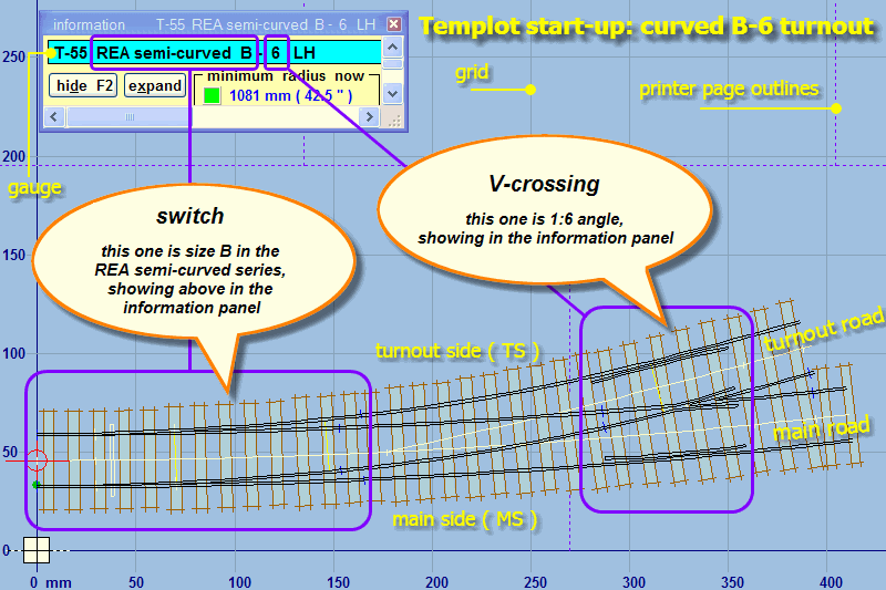
Every template has a turnout-side (TS) -- the diverging route, and a main side (MS) -- the straight-ahead route. The hand of the turnout doesn't come into it.

Plain track templates are also handed and have TS and MS -- the MS is indicated by a flag at the rail joint end. When a turnout is inserted into plain track, the turnout honours the hand and the TS and MS sides.

For a half-diamond template the turnout-side becomes the diagonal side (DS), although this change in designation doesn't always show in the dialogs, and there is no functional change.

A crossover consists of two separate templates, so each one has its own TS and MS.

This is all basic stuff which has been on the web site since the beginning of time, see:

https://85a.uk/templot/companion/gs_firstoff.php


startup_pad.png


cheers,

Martin.
 
_______________
message ref: 10048
Hi Martin,
yes I know all of that as you say basic stuff.
However when you create a crossover the control O peg reverses position between the two turnouts.
so how will that impact the snib naming? Will they nor reverse as some point in the crossover? given half the issue of snib collision happens at a crossover that could get very confusing. Given for a laser you would be trying to cut out the timbers as one continuous unit if possible
cheers
Phil,
 
_______________
message ref: 10049
Hi Martin,
yes I know all of that as you say basic stuff.
However when you create a crossover the control O peg reverses position between the two turnouts.
so how will that impact the snib naming? Will they nor reverse as some point in the crossover? given half the issue of snib collision happens at a crossover that could get very confusing. Given for a laser you would be trying to cut out the timbers as one continuous unit if possible
cheers
Phil,
@Phil G

Hi Phil,

When shoving timbers you are working on one template at a time. A crossover is two separate templates. Hold down the CTRL key and click one or the other to swap between them as the control template (make the control) as you deal with any conflicts.

cheers,

Martin.
 
_______________
message ref: 10050
Back
Top