Templot Club forums powered for Martin Wynne by XenForo :

TEMPLOT 3D PLUG TRACK - To get up to speed with this experimental project click here.   To watch an introductory video click here.   See the User Guide at Bexhill West.

   Templot5 - To join this open-source project on GitHub click here.  For news of the latest on-going developments click here.  Templot5 is now included with Templot2 - download.        WIKI

  • The Plug Track functions are experimental and still being developed. Some of the earlier pages of this topic are now out-of-date.

    For an updated overview of this project see this topic.   For some practical modelling aspects of using Plug Track see Building 3D Track.

    The assumption is that you have your own machines on which to experiment, or helpful friends with machines. Please do not send Templot files to commercial laser cutting or 3D printing firms while this project is still experimental, because the results are unpredictable and possibly wasteful.

    Some pages of this and other topics include contributions from members who are creating and posting their own CAD designs for 3D printing and laser-cutting. Do not confuse them with Templot's own exported CAD files. All files derived from Templot are © Martin Wynne.
  • The Plug Track functions are experimental and still being developed.

    For an updated overview of this project see this topic.   For some practical modelling aspects of using Plug Track see Building 3D Track.

    The assumption is that you have your own machines on which to experiment, or helpful friends with machines. Please do not send Templot files to commercial laser cutting or 3D printing firms while this project is still experimental, because the results are unpredictable and possibly wasteful.

    Some pages of this and other topics include contributions from members who are creating and posting their own CAD designs for 3D printing and laser-cutting. Do not confuse them with Templot's own exported CAD files. All files derived from Templot are © Martin Wynne.

Experimental 3D plug track - up to version 244c

Quick reply >
.
I have now added a spacer pad on the switch jigs to ensure the loose end of the rail is not pushed up out of the jig when tightening the bolt at that end.

This replaces the suggestion of using sticky tape for this purpose:

top_pad.png


The spacer pad can be turned off if not wanted.

Before anyone asks the same question every time I add anything -- yes, the dimensions of the pad can be changed. :) Click the set... button:


top_pad1.png


In the next program update.

cheers,

Martin.
 
_______________
message ref: 9749
Hi Martin,
If you were still thinking about modifying the F Jig to help me. all thought that would have been a great help it's no longer required, I have found my local 3D supplier also does some contract print work, and they have some big machines well capable of printing this filing jig.
So I will just go down that path.
cheers
Phil
 
_______________
message ref: 9750
_______________
message ref: 9764
@James Walters

Hi James,

Some interesting comments on your video, for some reason there is an assumption the rail is 3D-printed: :confused:

https://forum.mrhmag.com/post/3d-printed-track-12770271

Martin.
That's an American publication is it not?
Anyway seems to be more presumptions than actually spending time to understand what is being presented.
Maybe there is correlation in there after all!! That would in fact go along way to explain a lot of strange things going on over there these days.
Cheers
Phil,
 
_______________
message ref: 9765
For the uninitiated who doesn't bother to watch the video I guess its an easy (not excusable) mistake to make, as all other track pieces are 3D printed. Its nice for once to see the US behind the curve in scale layout building
 
_______________
message ref: 9767
.
Progress on the chair heaving function today:


heave_chairs_in_progress.png


Hopefully the chairs are self-explanatory. Flare-in and flare-out refers to wheels running in the facing direction through a crossing. Saddle chairs are small chairs which support the rail but do not have any jaws to locate it.

Currently available in plug track are S1, S1J, L1, CCL/CCR, CC, P, SC.

Which means there is still a lot to do in addition to the K-crossing chairs, and then any special chairs for slips, switch-diamonds, etc. Not forgetting the slab & bracket variants.

S1N chairs will need the bolt significantly modified to clear wheel flanges for 00/EM etc.

The SC fictional chairs are intended to be 3D printed without one or both jaws, so that they can be scratch-built to create specials. Not fully working yet.

cheers,

Martin.
 
_______________
message ref: 9789
.
Progress on the chair heaving function today:


View attachment 8189


Hopefully the chairs are self-explanatory. Flare-in and flare-out refers to wheels running in the facing direction through a crossing. Saddle chairs are small chairs which support the rail but do not have any jaws to locate it.

Currently available in plug track are S1, S1J, L1, CCL/CCR, CC, P, SC.

Which means there is still a lot to do in addition to the K-crossing chairs, and then any special chairs for slips, switch-diamonds, etc. Not forgetting the slab & bracket variants.

S1N chairs will need the bolt significantly modified to clear wheel flanges for 00/EM etc.

The SC fictional chairs are intended to be 3D printed without one or both jaws, so that they can be scratch-built to create specials. Not fully working yet.

cheers,

Martin.
Thank you for this Martin and thank you for what you have created this year. It really is appreciated. I have been silent for a while building baseboards but hopefully in the next few days I will be back making track.
 
_______________
message ref: 9790
Thanks you for all your efforts this year Martin, we all benefit from the great progress you are making with plug track.
By the way do you have any photos of S1N and S1O chairs.
cheers
Phil.
 
_______________
message ref: 9791
By the way do you have any photos of S1N and S1O chairs.
@Phil G

Hi Phil,

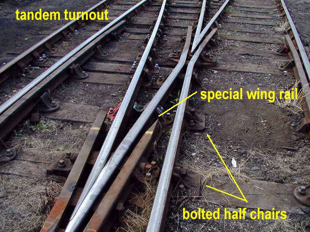
Not as clear as I would like. The primary reason we need them is for use in tandem turnouts.

Most of these photos show 11" wide GWR CS bolted half-chairs rather than 8" wide REA S1N and S1O, but used in similar situations -- i.e. where the standard chairs won't fit for some reason.

Here is a row of CS(OUTS) on a rail in a tandem where it passes too close to the V-crossing chairs to allow full space for normal chairs:

chairs03.jpg


chairs04.jpg


Notice also that the wing-rail flare has been machined to clear the wheel flanges on that rail.

The above photos © and linked from an excellent page of photos on the Scalefour Society web site:

https://www.scalefour.org/resources/trackdetails.html

Here is the best photo I can find of the need for at least one S1N where the first switch rail passes alongside the first P slide chair on the soleplate of the second switch in a tandem. A better photo of such would be welcome -- anyone?

s1n_s1o_pics1.jpg

© unknown


CS(INS) to clear the continuous check rail on the rail beyond:

s1n_s1o_pics4.jpg


Where nothing else would fit -- the "CS" is obscured but the "INS" marking is visible:

s1n_s1o_pics2.jpg


CS(OUTS) at the wing-rail front joint in a V-crossing:

s1n_s1o_pics3.jpg


cheers,

Martin.
 
_______________
message ref: 9792
Maybe I have missed it but how do I export the files to create the outside jaws and keys I can produce the inside jaw but that it.
David
@David Lane

Hi David,

loose_jaws1.png


click 1, then click 2:

loose_jaws2.png


Martin.
 
_______________
message ref: 9811
By the way do you have any photos of S1N and S1O chairs.

The primary reason we need them is for use in tandem turnouts.

@Phil G

Here are some diagrams of tandem turnouts, showing some of the chairs needed:


tandem_sizes.png


Click the image twice to see full hi-res scan. Sorry the quality is poor.

Looking closely at them, the need for the chair heaving function is obvious. Several S1N and S1O needed, plus several others also not yet done. There are more M1 than you might think, and they are going to be tricky for the loose jaws. This is A-7+A-7 tandem:


tandem_size_a7_a7.png


The top-most check rail is longer than it needs to be on the right, purely to allow for the chairing to fit.

The process of chair heaving on complex formations is going to be fun, and a lot to learn. :)

cheers,

Martin.
 
_______________
message ref: 9824
.
Progress on the chair heaving function today:


View attachment 8189


Hopefully the chairs are self-explanatory. Flare-in and flare-out refers to wheels running in the facing direction through a crossing. Saddle chairs are small chairs which support the rail but do not have any jaws to locate it.

Currently available in plug track are S1, S1J, L1, CCL/CCR, CC, P, SC.

Which means there is still a lot to do in addition to the K-crossing chairs, and then any special chairs for slips, switch-diamonds, etc. Not forgetting the slab & bracket variants.

S1N chairs will need the bolt significantly modified to clear wheel flanges for 00/EM etc.

The SC fictional chairs are intended to be 3D printed without one or both jaws, so that they can be scratch-built to create specials. Not fully working yet.

cheers,

Martin.

Now up to 21 heavable (interchangeable) chairs:


heavable_chairs.png


Which is surely enough. It's going to be a while before all these are available. Just getting this dialog working is no 5-minute task. :)

Martin.
 
_______________
message ref: 9825
Hi Martin,

Great work, I don't think I have come across saddle chairs before. The rest I know about and have experience of, except the switched diamond slide chairs, as there are non on the ESR.
 
_______________
message ref: 9826
Hi Martin,

Great work, I don't think I have come across saddle chairs before. The rest I know about and have experience of, except the switched diamond slide chairs, as there are non on the ESR.
@Phil O

Hi Phil,

This is a SS saddle chair. Supports the rail, but without any jaws. Used where the jaws would be impossible to access because of other rails in the way. Quite rare. Same size as S1 but with 4 screws:

saddle_chair.png


The MS saddle chair is much smaller and the same size as an M1 bridge chair:

ms_saddle_chair.png


SDS switch-diamond heel slide chair. No key on the outside, and just a short slide pad. Used on the switch rail where the 1P and 2P block chairs would be in a normal switch. The jaw is 6" wide instead of the normal 4":


sds_chair.png


The SDP switch-diamond slide chair is similar to a normal P slide chair, but 3" longer. There would usually be two of them on each side of the switch-diamond. There are several other special chairs in a switch-diamond, but specific to the crossing angle so not interchangeable.

Just to clarify. I have created the full list of these heavable (interchangeable) chairs for plug track, but that is all it is so far -- a list. :) I haven't yet done all the actual chairs. The first new ones will be S1O and S1N.

Interchangeable means they are always the same on different templates* and can be 3D printed in bulk if desired. Heavable means they can be swapped to replace the normal chair at any position if required when creating custom formations.

*of the same gauge/scale/flangeway/rail section.

cheers,

Martin.
 
_______________
message ref: 9827
Hi Martin,
That's very good info, it sounds as though there could be cases, where several interchangeable chairs will need heaving out and replaced with these special chairs.
Is there any sort of logic we should use in terms of finding the right special chair to fit in the place of the normal interchangeable chair? And will plug track know an interchangeable chair will not fit? Even if it can't tell us which chair to heave in it place?
cheers
Phil,
 
_______________
message ref: 9829
Hi Martin,
That's very good info, it sounds as though there could be cases, where several interchangeable chairs will need heaving out and replaced with these special chairs.
Is there any sort of logic we should use in terms of finding the right special chair to fit in the place of the normal interchangeable chair? And will plug track know an interchangeable chair will not fit? Even if it can't tell us which chair to heave in it place?
cheers
Phil,
@Phil G

Hi Phil,

You are jumping ahead too fast. Until I've got more chairs done and the heaving function working it's impossible to say what tricks and tips we might learn when using them.

1. There are two slightly different situations to consider. Most often you might want to build up complex formations using partial templates in the normal way. Here for example is an outside slip being created:


chairing_outside_slip.png


A row of L1 bridge chairs has been placed on the switch rail where it passes alongside the V-crossing. It's clear that the first 2 are ok, but the remainder will conflict with the crossing chairs. The solution is to heave them out of the way and use S1N chairs instead in those positions.

Templot won't be able to tell you which chairs to use, but it should be able to warn you that the existing chairs are conflicting and something needs to be done about it. But I haven't written that warning function yet.

In cases like this the most likely replacement chairs needed will be L1, M1, S1O, S1N. You are not going to need a lone P chair or an SDS chair in the middle of a scissors crossover! So the full list of 21 heavable chairs is a bit misleading.

2. In other situations you might be creating custom switches and crossings - for industrial, light railways, narrow gauge, etc. In which case you might need to add a row of P chairs to a length of plain rail to create a custom switch. When we get that far I'm sure there will be lots of new tick-boxes and options needed, but we are not there yet.

cheers,

Martin.
 
_______________
message ref: 9830
You are jumping ahead too fast. Until I've got more chairs done and the heaving function working it's impossible to say what tricks and tips we might learn when using them.
Hi Martin,
Thanks for the reply you have given me something like the answer I was hoping for. I am fully aware there is a lot of water to pass under the bridge before we are in a real world chair heaving situation.
I don't think I was jumping ahead too fast, maybe just asking in a roundabout way if there was any sort of literature that would help make the right choice, when it comes to which chairs to use.
Given most books or articles on this subject are well out of print, It does take time to track such works down if in fact you can.

If there are any recommendations I would gladly start trying to hunt them down.

You should also be mindful very few of us have you vast knowledge of railway track design detail, so we are not going to simply know, what to heave in each time.

In the first the example you have given I do think we can work out, that P type special chairs are not what we are looking for. :)

Also using the logic of normal turnouts it does seem the standard thinking is to replace S1 chair firstly with L1 chairs, so I am presuming there is a cascading down plan in play here, i.e. if the L1 will not fit try an M1, and if that does not fit use a half chair! or maybe a saddle.
would that be about right?
cheers
Phil
 
_______________
message ref: 9831
Also using the logic of normal turnouts it does seem the standard thinking is to replace S1 chair firstly with L1 chairs, so I am presuming there is a cascading down plan in play here, i.e. if the L1 will not fit try an M1, and if that does not fit use a half chair! or maybe a saddle.
would that be about right?
@Phil G

Hi Phil,

That's about right, although not the SS saddle to replace an S1 because it is the same size as an S1. Generally the p.w. gang would probably prefer that you don't use half-bolted chairs unless unavoidable, because it involves drilling holes in the rail.

On the prototype the first thought might be to try a little timber shoving under the chairs to see if that might allow any conflict to be eased. That's easier with equalized timbers than square-on, in keeping the chair screws away from the edge of the timber.

In Templot timber shoving will have a more significant unprototypical effect because Templot recalculates the crossing chairs on the new shoved timber centres. That's either a good thing (if you are modelling in 00, EM, etc. and need to allow for the wider flangeways=longer chairs) or a bad thing (if you are modelling in P4, etc. and don't).

Which means in P4 you need to know not to shove the timbers under the crossing chairs if you want the result to be prototypical. There is no prototype for 00 or EM trackwork, so you can be less constrained if you wish. Even in P4 the flangeways are 15% overscale = longer chairs, so you might think some minor tweaking is acceptable.

The difference the flangeway makes to the size of the crossing chairs is significant -- here are the BB chairs for a 1:8 crossing, EM on the left, S4-X (exact scale) on the right:


flangeway_longer_chair.png


If you want to have conflicting chairs shifted sideways on a timber, i.e. away from the timber centre-line, it will be necessary to hide the timber outline and put in a replacement timber on a separate partial template.

If you are looking for textbooks explaining the black arts of timber shoving and chairing, I suspect each design office had their own established ways of doing things. BRT3 has some general remarks on p.153. There is some explanation of GWR practice in:

cvr_track_400px.jpg


See: https://85a.uk/templot/club/index.php?threads/bullhead-track-books.769/post-8824

cheers,

Martin.
 
_______________
message ref: 9832
Hi Martin,
Thank you very helpful indeed. It all makes a lot more sense to me now.
The only thing I still have no idea about is the saddle chair! If its the same size as an S1, when and why would you need to think about using a saddle chair?
I have copies of both books you mentioned, although right now their still somewhere between the UK and NZ. hopefully not stuck in the typical posting holdups that are so common this time of year. once they arrive I will have a very good look at them. Do you know if by chance the LMS study group have anything like the GWR book? or an I dreaming :)
cheers
Phil,
 
_______________
message ref: 9833
Generally the p.w. gang would probably prefer that you don't use half-bolted chairs unless unavoidable, because it involves drilling holes in the rail.
Hi Martin,
On further refection we are in fact very much in the same position as the PW gang, but not quite for the same reason, ( I am making the presumption S1O and S1N chairs are more cosmetic then functional in our case)
Although drilling very small holes (14 or 16 Ba) in the sides of rails to make them more functional does not appeal to me, anymore than it did to the PW gang back in the day :)
cheers
Phil.
 
_______________
message ref: 9834
The only thing I still have no idea about is the saddle chair! If its the same size as an S1, when and why would you need to think about using a saddle chair?
@Phil G

Hi Phil,

It's a good question for the SS saddle! I suspect it is a legacy from the use of interlaced timbering in pre-group days. Something like this might arise:


saddle_chair_use.png


Clearly it is not possible to have an outer jaw on the middle chair because the lower rail would conflict with it. But the upper rail needs support, so a jawless saddle chair might be used there. In the above example an S1N half-bolted chair might have been better, but suppose there is another rail on that side too? Some early pre-grouping formations were very complex.

On reflection, even an SS saddle chair is not feasible there, because the rail will conflict with the head of the chair screws. So in practice it would more likely be an MS saddle.

For the model half-bolted chairs I suspect a smear of epoxy might come into play, as for the P slide chairs -- although who knows in the larger scales? If suitable bolts can't be sourced, perhaps we could 3D print them? :)

cheers,

Martin.
 
_______________
message ref: 9835
Hi Martin,

Could you print the "T" bolt that fits in the web?
View attachment 8268

I didn't think to take a photo of one.
@Phil O

Hi Phil,

Well here's the GWR drawing if you want to try it -- functional or cosmetic thread. :)

gwr_slide_chair_bolt.png


The drawing is dated Paddington, March 1938. So presumably "new" means switches installed/renewed after that date. I can't find a drawing of the "special" lock nuts. The standard nut is 1.5/8" sq.

No information about the thread, but I would be surprised if it's not 1" Whit. (1/8" pitch):

https://www.britishmetrics.com/images/pdf/technical/bswstd_1.htm

cheers,

Martin.
 
_______________
message ref: 9837
Hi Martin/Phil,
I am a bit confused here, normally looking at that drawing I would have concluded the head on the web side was round, but with Phil's comment about a Tee bolt its possible its not round at all, and there is a view missing from the drawing.
can either of you confirm the shape of the head?. and if GWR and REA were the same in this case?

Re the thread, just wondering if the PW gang also used Whitworth railway threads, or more accurately boiler threads. Where the pitch is a constant 11 TPI irrespective of the OD? maybe not. As the boiler thread was a constant 11 TPI for two another reasons.
cheers
Phil
 
_______________
message ref: 9838
Hi Martin/Phil,
I am a bit confused here, normally looking at that drawing I would have concluded the head on the web side was round, but with Phil's comment about a Tee bolt its possible its not round at all, and there is a view missing from the drawing.
can either of you confirm the shape of the head?. and if GWR and REA were the same in this case?

Re the thread, just wondering if the PW gang also used Whitworth railway threads, or more accurately boiler threads. Where the pitch is a constant 11 TPI irrespective of the OD? maybe not. As the boiler thread was a constant 11 TPI for two another reasons.
cheers
Phil
@Phil G

Hi Phil,

The GWR drawing shows the head as 3.1/8" x 2" square. The 3.1/8" dimension to fish fit on the rail.

The REA version has a separate 4" wide fish washer, having a square hole. The bolt has a square neck below the head to fit.

I can't find any definitive info on the thread for these 1" bolts.

However, for ordinary 15/16" dia. fish-bolts:

REA: 9 TPI BSW

GWR: BS-95R rail: 9 TPI BSW

GWR '00' rail: 11TPI BSF

GWR (and REA?) with insulated fishplates (track-circuits): 11 TPI BSF

cheers,

Martin.
 
_______________
message ref: 9845
Happy New Year to you all!

I'm sorry to hear about your accident, Martin, and I hope you are feeling better.

I've been away in the States, a house move and Christmas and I've noticed the regular Zoom meetings have disappeared. Is there any plan to re-introduce regular meetings?

Martin
 
_______________
message ref: 9856
Happy New Year to you all!

I'm sorry to hear about your accident, Martin, and I hope you are feeling better.

I've been away in the States, a house move and Christmas and I've noticed the regular Zoom meetings have disappeared. Is there any plan to re-introduce regular meetings?

Martin
@NoIdea

Hi Martin,

Thanks for your concern. It's getting better, but it will be several months to a full recovery, or as much as is possible.

Next Zoom meeting is on Monday 8th January, see:

https://85a.uk/templot/club/index.php?threads/zoom-meetings.599/post-9850

cheers,

Martin.
 
_______________
message ref: 9858
.
For the next program update I'm increasing the default FDM timber thickness to 10.08 inches full-size.

In 4mm/ft scale this equates to 3.36mm instead of the previous 3.24mm. Two reasons for this change:

1. it's a multiple of both 0.12mm (28 layers) and 0.16mm (21 layers), ensuring that timbering bases printed at either setting will match exactly for thickness.*

I'm using 0.12mm layers in a custom printer profile, but I know many 3D printers have a standard Fine profile with 0.16mm layers.

2. I've found that the large crossing chairs don't always cut as cleanly from the raft supports as the smaller chairs, leaving broken remains of the support on the bottom of the plug. A slightly deeper socket provides a bit more clearance to ensure the chair can clip fully home, although it's always a good idea to give the bottom of the plug a quick rub with a file.

But if preferred the timber dimensions can be set to whatever you want. In scales other than 4mm/ft I can imagine most users will want to use their own timber thickness settings:


timber_sizes.png


*This assumes that FDM shrinkage is independent of layer thickness. Which is probably not the case, but we have to draw the line on complexity somewhere. All settings can be adjusted if desired.

Martin.

@James Walters
 
_______________
message ref: 9879
Hi Martin,
I am assuming for the depth of vee angle you are creating for the switch rail slider, these will also increase, which is another positive step.
Cheers
phil,
 
_______________
message ref: 9880
Hi Martin,
I am assuming for the depth of vee angle you are creating for the switch rail slider, these will also increase, which is another positive step.
Cheers
phil,
@Phil G @James Walters

Hi Phil,

I've modified the default slider ribs to make all dimensions in 4mm/ft scale multiples of 0.12mm and 0.16mm to ensure the slider (not yet done) will work equally well with either. This has resulted in slightly chunkier ribs, which will be a bit less fiddly to assemble:
revised_slider_ribs.png

But they can be set to whatever dimensions or angle you want (or switched off entirely):


slider_ribs_button.png


cheers,

Martin.
 
_______________
message ref: 9881
.
For the next program update I'm increasing the default FDM timber thickness to 10.08 inches full-size.

In 4mm/ft scale this equates to 3.36mm instead of the previous 3.24mm. Two reasons for this change:

1. it's a multiple of both 0.12mm (28 layers) and 0.16mm (21 layers), ensuring that timbering bases printed at either setting will match exactly for thickness.*

I'm using 0.12mm layers in a custom printer profile, but I know many 3D printers have a standard Fine profile with 0.16mm layers.

2. I've found that the large crossing chairs don't always cut as cleanly from the raft supports as the smaller chairs, leaving broken remains of the support on the bottom of the plug. A slightly deeper socket provides a bit more clearance to ensure the chair can clip fully home, although it's always a good idea to give the bottom of the plug a quick rub with a file.

But if preferred the timber dimensions can be set to whatever you want. In scales other than 4mm/ft I can imagine most users will want to use their own timber thickness settings:


View attachment 8303


*This assumes that FDM shrinkage is independent of layer thickness. Which is probably not the case, but we have to draw the line on complexity somewhere. All settings can be adjusted if desired.

Martin.

@James Walters

Martin

Thank you for this. Just so that I understand. Few months ago I reduced my plug depth by 1mm. I did this when I was trying out lots of different settings and for whatever reason this has been my default.

So I changed the 3.08mm and 3.32 below to 2.08 and 2.32. This gives me a total plug track timber print depth of 3.78mm which in S Scale is approx 9.5 inches....

Will I need to do anything different once you have made this change or can I just carry on with the above settings?

1704538699440.png


1704538011306.png
 
_______________
message ref: 9882
Will I need to do anything different once you have made this change or can I just carry on with the above settings?
@Michael Woods

Hi Michael,

Just carry on entering whatever dimensions you wish. Changes to the plug sizes do not affect the timber thickness.

However, this change means that the timber thickness will be showing a different default dimension (4.0mm instead of 3.86mm previously in S scale):

s_scale_timber_sizes.png


Your 3.78mm measured on the finished timbers is after shrinkage. If you want to make any new bases match your existing ones, you will need to change the 4.0mm back to 3.86mm before exporting the file.

I'm sorry if this has added one more step to remember -- eventually it will be possible to save all your settings in a custom settings file to make it easy to reload them each time, but that's not fully working yet.

This change will be in 243b program update, but it won't be for a while yet.

cheers,

Martin.
 
_______________
message ref: 9883
@Michael Woods

Hi Michael,

Just carry on entering whatever dimensions you wish. Changes to the plug sizes do not affect the timber thickness.

However, this change means that the timber thickness will be showing a different default dimension (4.0mm instead of 3.86mm previously in S scale):

View attachment 8314

Your 3.78mm measured on the finished timbers is after shrinkage. If you want to make any new bases match your existing ones, you will need to change the 4.0mm back to 3.86mm before exporting the file.

I'm sorry if this has added one more step to remember -- eventually it will be possible to save all your settings in a custom settings file to make it easy to reload them each time, but that's not fully working yet.

This change will be in 243b program update, but it won't be for a while yet.

cheers,

Martin.
Martin - thank you - no problem with changing the setting - I have a check list that I work through before printing anything. I have most of the STLs sorted for the whole layout now so I am working more on the printer than on Templot. The catch points will wait until chair heaving is ready but there is no rush on that I have more than enough to keep me busy for the next few months...
 
_______________
message ref: 9885
.
Another day, more buttons, another dialog. :)

The Zoom meeting last night left me doing a lot of thinking.

This present dialog:

jaw_options.png


applies to all the chairs of each type on the template.

Which is fine as far as it goes when considering the 3D printing process, but may actually be overkill in terms of track design. I suspect that many users never go beyond clicking the top 3 buttons to set all chairs at once.

Whereas when we get to K-crossings, tandem turnouts, other complex formations, there is more likely to be a need to make these settings individually for a single specific chair. Especially in the very small scales.

And also to choose the plug fit individually for a single specific chair, which at present can't be done. You can mix and match the fit from a mixed stock of ready-printed chairs, but not have mixed-fit sockets in a single timbering base. It may be that choosing loose jaws means that the clip-fit tangs won't be an option on some chairs. So some forward planning of the assembly sequence may be needed at the design stage.

Which means we need:

customize_heaved.png


Which will be a lot more coding work, but I keep saying I enjoy it. :)

Which is true, but there are no two ways about it -- someone else is going to have to write up the explanation for all this. It's all getting a bit too much for me.

cheers,

Martin.
 
_______________
message ref: 9909
Is there any chance of adding a "save all plug track settings" option in a named file, so that when we open Templot next (even with a different piece of track) we can simply select from an archive of our custom settings to use for different purposes?

I only ask because it can get a bit laborious entering in all the changes I need to do for N gauge rails every time...

Thanks,

Ross.
 
_______________
message ref: 9915
Is there any chance of adding a "save all plug track settings" option in a named file, so that when we open Templot next (even with a different piece of track) we can simply select from an archive of our custom settings to use for different purposes?

I only ask because it can get a bit laborious entering in all the changes I need to do for N gauge rails every time...

Thanks,

Ross.
@RBTKraisee

Hi Ross,

Like everything else, it is work-in-progress:

custom_data.png


At present some settings are saved, many are not. It's on my to-do list, but I can only do so much at a time. Sorry.

cheers,

Martin.
 
_______________
message ref: 9918
@James Walters

Another day, 4 more tick-boxes. :)

Thinking about the 2-D laser snibs, it's clear that even a simple formation such as a crossover is going to create some significant conflicts between the snib cuts and nearby timbers:

snib_conflicts.png


The thinking so far has been that users will edit this stuff in their laser CAD. But that looks tedious to do, and it would be better if the conflicts weren't there in the first place.

So in the next program update it will be possible to omit any of the 4 snibs on each timber as required:


snibs_tickboxes.png


That's still quite a lot of clicking to select timbers and untick the relevant tick-boxes, but the changes will be saved in the BOX file so that a laser cut can be repeated or the track plan modified without needing to redo all the CAD editing.

It will also be possible to omit all the snibs along one or both sides of a specific template:


snibs_options.png


The nibs will remain and shouldn't usually cause any conflicts.

This is only relevant in 2-D exports -- the settings are ignored in 3-D exports.

Will be in 244a before too long.

cheers,

Martin.
 
_______________
message ref: 9951
Back
Top